S-series IS Electronic Marshalling - Emerson Process Management
S-series IS Electronic Marshalling - Emerson Process Management
S-series IS Electronic Marshalling - Emerson Process Management
Create successful ePaper yourself
Turn your PDF publications into a flip-book with our unique Google optimized e-Paper software.
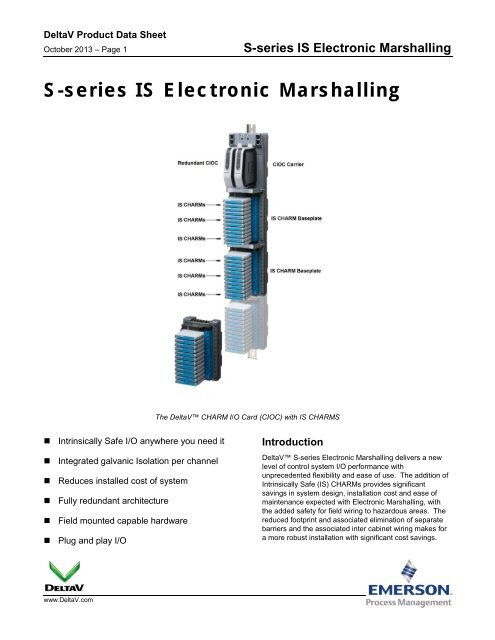
DeltaV Product Data SheetOctober 2013 – Page 4S-<strong>series</strong> <strong>IS</strong> <strong>Electronic</strong> <strong>Marshalling</strong>• Green Solid: Normal Operation• Green Blink: Normal awaiting configuration• Red Blink: Fault detected on wiring• Red Solid: Internal Fault detectedDiscrete <strong>IS</strong> CHARMs have a Yellow LED to indicate thestate of the field signal.All <strong>IS</strong> CHARMs meet <strong>IS</strong>A 71.04-1985 severity level G3(harsh) corrosion specifications.The <strong>IS</strong> DI NAMUR CHARM supports a pulse counter witha maximum frequency of 10 KHz.<strong>IS</strong> CHARM Latch MechanismThe CIOC communicates over a redundant Ethernetnetwork with up to 4 controllers, allowing great flexibilityand ease of system expansion. Additional controllers canbe added to accommodate increased control scope andI/O can be reassigned without changing the physicalwiring.<strong>IS</strong> CHARMs can be added to any existing <strong>IS</strong> baseplateposition and autosensed online. Additional CIOC’s can beadded online.<strong>IS</strong> CHARM TypesA variety of analog and discrete <strong>IS</strong> CHARMs are availableto meet your specific requirements. . The following <strong>IS</strong>CHARMs are available starting with v11.3.1:• <strong>IS</strong> AI 4-20 mA HART• <strong>IS</strong> RTD• <strong>IS</strong> Thermocouple / mV• <strong>IS</strong> AO 4-20 mA HART• <strong>IS</strong> DI NAMUR• <strong>IS</strong> DO 45 mAAll <strong>IS</strong> CHARMs have a bi-color Power/Integrity LED thatindicates the health of the <strong>IS</strong> CHARM. The indicationsprovide clear, actionable instruction to the maintenancepersonnel.I/O Terminal Block Options<strong>IS</strong> CHARMs are designed to work with the <strong>IS</strong> TerminalBlocks, which are light blue in color, designating the fieldwiring as intrinsically safe. <strong>IS</strong> CHARMs are mechanicallydifferent and will not install in non-<strong>IS</strong> terminal blocks,ensuring there is no error in the installation.There are 2 different <strong>IS</strong> Terminal blocks available to meetthe wiring needs of field signals.• <strong>IS</strong> Terminal Block• <strong>IS</strong> Thermocouple / mV Terminal BlockThe <strong>IS</strong> Terminal block has 4 terminals, supporting thetraditional discrete and analog 2 & 4 wire sensor/actor fieldinstrumentation signals as well 2, 3 and 4 wire RTDSensorsThe <strong>IS</strong> Thermocouple / mV Terminal Block is speciallydesigned for the usage with the <strong>IS</strong> Thermocouple / mVCHARM. The <strong>IS</strong> Thermocouple / mV Terminal Block and<strong>IS</strong> Thermocouple / mV CHARM can only be ordered as anAssembly.<strong>IS</strong> CHARM Keying PostsThe <strong>IS</strong> Terminal Blocks contain keying posts that areautomatically set and locked to the unique position of theinstalled <strong>IS</strong> CHARM. The keys prevent the insertion of anincorrect <strong>IS</strong> CHARM during maintenance activities. The <strong>IS</strong>Terminal Blocks are shipped with the keys in a neutralposition and are set when an <strong>IS</strong> CHARM is inserted. Ifneeded, the keys can be manually reset to allow a channelto be re-tasked for a different signal type.The keying mechanism consists of two keying posts thatrotate and lock into the <strong>IS</strong> terminal block base. Each <strong>IS</strong>CHARM type is assigned a unique key setting
DeltaV Product Data SheetOctober 2013 – Page 5S-<strong>series</strong> <strong>IS</strong> <strong>Electronic</strong> <strong>Marshalling</strong><strong>IS</strong> CHARM Baseplates<strong>IS</strong> CHARM baseplates are mechanically different thannon-<strong>IS</strong> baseplates, ensuring there is no error in theinstallation of the Terminal Blocks or CHARMs (non-<strong>IS</strong>).A baseplate separator is needed on the beginning and onthe end of any <strong>IS</strong> CHARM baseplate row, also in betweenany of the <strong>IS</strong> CHARM baseplates. You can add <strong>IS</strong>CHARM baseplates to non-<strong>IS</strong> CHARM baseplates andany of the other components, like the CIOC carrier,CHARM baseplate extenders and CHARM baseplateTerminators.<strong>IS</strong> CHARM Terminal block.Hardware SpecificationsCommon Environmental Specifications (all components)Operating temperature -40 to 70 °C (-40 to 158 °F) *Storage temperatureRelative humidity-40 to 85 °C (-40 to 185 °F)5 to 95% , non-condensingProtection rating IP 20, NEMA 12Airborne contaminantsShock<strong>IS</strong>A-S71.04-1985 Airborne Contaminants Class G3Conformal coating10 g ½-sine wave for 11 msVibration1 mm peak-to-peak from 2 to 13.2 Hz;0.7 g from 13.2 to 150 Hz* When used with copper Ethernet I/O Ports (Copper IOP). When used with the Fiber Optic I/O Ports (Fiber Optic IOP), the operatingtemperature range is limited to -40 to 60 °C (-40 to 140 °F).
DeltaV Product Data SheetOctober 2013 – Page 6S-<strong>series</strong> <strong>IS</strong> <strong>Electronic</strong> <strong>Marshalling</strong>CHARM I/O Card and CarrierOperating Temperature -40 to 70 °C (-40 to 158 °F)Operating Temperature -40 to 60 °C (-40 to 140 °F)CIOC Carrier Ethernet Communication Modules
DeltaV Product Data SheetOctober 2013 – Page 7S-<strong>series</strong> <strong>IS</strong> <strong>Electronic</strong> <strong>Marshalling</strong><strong>IS</strong> CHARM Baseplate with Separator, <strong>IS</strong> CHARMs and Label Plates in PlaceCHARM Baseplate Terminator, TopCHARM Baseplate Terminator, Bottom
DeltaV Product Data SheetOctober 2013 – Page 8S-<strong>series</strong> <strong>IS</strong> <strong>Electronic</strong> <strong>Marshalling</strong>CHARM Baseplate Extender, TopCHARM Baseplate Extender, Bottom<strong>IS</strong> CHARM
DeltaV Product Data SheetOctober 2013 – Page 9S-<strong>series</strong> <strong>IS</strong> <strong>Electronic</strong> <strong>Marshalling</strong><strong>IS</strong> CHARM Terminal Block<strong>IS</strong> CHARM Thermocouple / mV Terminal Block
DeltaV Product Data SheetOctober 2013 – Page 10S-<strong>series</strong> <strong>IS</strong> <strong>Electronic</strong> <strong>Marshalling</strong>Address PlugAddress Plug Terminal Block for <strong>IS</strong> Baseplate
DeltaV Product Data SheetOctober 2013 – Page 11S-<strong>series</strong> <strong>IS</strong> <strong>Electronic</strong> <strong>Marshalling</strong>CHARM I/O Card HardwareSpecifications for CHARM I/O Card CarrierNumber of I/O Cards per carrierInput power (redundant)Redundant Ethernet connectionsMounting2 (redundant pair)24 VDC ±10% at 12 A maximumFiber-optic: 100BASE-FX with MTRJ connectors;- Full duplex operation;- Multi-mode - 2 km nominal distance.• Copper twisted pair: 10/100BASE-TX with RJ45 connectors;- Half/Full duplex operation- 100 m distanceDIN rail Latch to T-type railSpecifications for CHARM I/O CardNumber of I/O ChannelsNumber of I/O Clients96 Channels, Individually defined signal types4 (Controllers)Number of CIOC’s per Controller 16Number of CIOC’s per system 300I/O update ratesUser memoryCIOC power (24 VDC)CIOC Heat Dissipation50ms, 100ms, 250ms, 500msN/A0.28 Amps per Redundant CIOC node(includes two cards and two communication modules)(individual CHARM power requirements are in addition)8 Watts max. per Redundant CIOC node- 2.0 Watts per CIOC- 1.34 Watts per Copper Ethernet I/O Communication Port- 2.0 Watts per Fiber Optic I/O Communication PortCIOC output to CHARMs 6.3 VDC redundant power, at 3.25 A maximum *Fuse Protection (internal)MountingCommunicationNetwork AddressingInternal Non-replaceable Fuse2-wide CHARM I/O CarrierRedundant Ethernet connections via CHARM I/O CarrierAuto Assigned during commissioningLED Indicators:Green – PowerRed – ErrorGreen – Active/StandbyYellow flashing – Pri./Sec. CNIndicates DC power is applied.Indicates an error condition.Indicates operating mode of each CIOCIndicates valid control network communication.* Actual CIOC Output to CHARMs is dependent on number of installed CHARMs
DeltaV Product Data SheetOctober 2013 – Page 12S-<strong>series</strong> <strong>IS</strong> <strong>Electronic</strong> <strong>Marshalling</strong><strong>IS</strong> CHARMs Baseplate HardwareSpecifications for <strong>IS</strong> CHARM BaseplateNumber of channels per baseplate 12Number of base plates per CIOC 8Addressing One Address Plug (1 through 8)Terminal blocksShield connectionsWire strip lengthMounting- Standard <strong>IS</strong> Terminal Block (Light Blue)- <strong>IS</strong> Thermocouple / mV Terminal Block (Light Blue)1 Screw Cage terminal per channel, plus 1 for cable shield0.32 – 2.5 mm 2 / 22 – 14 AWGGold plated connectors for shield continuity7 - 9 mm / 0.28 – 0.36 in.DIN rail Latch to T-type railSpecifications for <strong>IS</strong> Baseplate Termination, Top and BottomShield Drain wire connectionsWire strip length2 Screw Cage Terminals0.32 – 2.5 mm 2 / 22 – 14 AWG7 - 9 mm / 0.28 – 0.36 in.Specifications for Baseplate Extenders, Top and BottomPrimary Bus connectionSecondary Bus connection9-pin D-shell,Primary RS-485 communications busPrimary 24 VDC field powerPrimary CHARM power9-pin D-shell,Secondary RS-485 communications busSecondary 24 VDC field powerSecondary CHARM powerSpecifications for Extender CablesMaximum bus length (includingBaseplates)5.5 m (18 ft)Available Cable lengths 2 m, 1 m, 0.5 m (6.7 ft, 3.3 ft, 1.6 ft )
DeltaV Product Data SheetOctober 2013 – Page 13S-<strong>series</strong> <strong>IS</strong> <strong>Electronic</strong> <strong>Marshalling</strong>Specifications for <strong>IS</strong> Terminal BlockNumber of connectionsStrip length4 Screw Cage terminals0.32 – 2.5 mm 2 / 22 – 14 AWG7 - 9 mm / 0.28 – 0.36 in.Maximum Current 45 mA at 28 VDC max. *ColorLight BlueSpecifications for <strong>IS</strong> Thermocouple / mV Terminal BlockNumber of connectionsStrip length2 Screw Cage terminals0.32 – 2.5 mm 2 / 22 – 14 AWG7 - 9 mm / 0.28 – 0.36 in.Maximum Current 45 mA at 28 VDC max. *ColorLight BlueSpecifications for Address Plug Terminal BlockNumber of connectionsColornoneBlack* Actual Current draw is determined by type of CHARM and associated field devices.
DeltaV Product Data SheetOctober 2013 – Page 14S-<strong>series</strong> <strong>IS</strong> <strong>Electronic</strong> <strong>Marshalling</strong><strong>IS</strong> Analog Input CHARMSensor TypesNominal signal range (span)Full signal rangeInput ImpedanceField Power (2-wire)Specifications for <strong>IS</strong> AI 4-20 mA HART CHARM4-20 mA with or without HARTSupports 2-wire and 4-wire device types4-20 mA, (0-20 mA optional)0 to 22 mA< 303 Ω16.0 V(min) at 20 mAAccuracy over temperature range 0.1% of span (0-60º C)RepeatabilityResolutionCalibrationDC/50/60 Hz Common moderejection0.25% of span (over -40 -70º C)0.05% of span16 bit A/D converterNone requiredN/AIsolation Galvanically isolated according to EN 60079-11.Voltage peak value 375 VDC.Field Circuit (2-wire Transmitter)- Voltage Uo- Current Io- Power PoField Circuit (2-wire Current Source)- Voltage Uo- Current Io- Voltage Ui- Current Ii- Current Pi(Connect between field terminals 3+, 4-)- 27.3 V- 93 mA- 635 mW (linear Characteristic)(Connect between field terminals 4+, 2-)- 27.3 V- negligible- 28 V- 110 mA- 2.121 WCHARM power req. 60 mA max @ 24 VDC ±10%CHARM Heat DissipationHART supportHART data update rates0.86 WHART v7 pass-through for AMSHART v7 variable and device status available to control500 ms
DeltaV Product Data SheetOctober 2013 – Page 15S-<strong>series</strong> <strong>IS</strong> <strong>Electronic</strong> <strong>Marshalling</strong>Simplified Circuit and Connection Diagrams for <strong>IS</strong> AI-CHARM 4 to 20 mA HART Two Wire and Four Wire transmitters
DeltaV Product Data SheetOctober 2013 – Page 16S-<strong>series</strong> <strong>IS</strong> <strong>Electronic</strong> <strong>Marshalling</strong><strong>IS</strong> RTD CHARMSpecifications for <strong>IS</strong> RTD Input CHARMSensor typesSensor ConfigurationFull Scale signal rangeAccuracyRepeatabilityResolutionCalibrationSensor excitation currentDC/50/60 Hz Common moderejectionRTD input (Types listed in Table)2 wire, 3 wire, or 4 wireSee Table next pageSee Table next page0.05% of span24 bit A/D converter / Depends upon the sensor typeNone required0.5 mA in 2-wire and 4 wire configurations0.25 mA in 3-wire90dB typicalIsolation Galvanically isolated according to EN 60079-11.Voltage peak value 375 VDC.Open sensor detectionField Circuit- Voltage Uo- Current Io- Power PoCHARM power req.CHARM Heat DissipationYes(Connect between field terminals 1-, 2+, 3-, 4+)- 6.51 V- 43.50 mA- 71 mW (linear Characteristic)23 mA max @ 24 VDC0.60 W
DeltaV Product Data SheetOctober 2013 – Page 17S-<strong>series</strong> <strong>IS</strong> <strong>Electronic</strong> <strong>Marshalling</strong>Sensor TypeRTD, ohms Sensor Type SpecificationsOperatingRange25° ReferenceAccuracy (4-wire)TemperatureDrift (4-wire)ResolutionPt100 -200 to 850°C ± 0.50° C ± 0.015° C/°C ~0.02° CPt200 -200 to 850°C ± 0.40° C ± 0.014° C/°C ~0.02° CPt500 -200 to 850°C ± 0.34° C ± 0.014° C/°C ~0.02° CPt1000 -200 to 260°C ± 0.14° C ± 0.006° C/°C ~0.01° CNi120 -80 to 260°C ± 0.18° C ± 0.003° C/°C ~0.01° CNi100 -80 to 260°C ± 0.12° C ± 0.003° C/°C ~0.01° CNi200 -80 to 260°C ± 0.11° C ± 0.003° C/°C ~0.01° CNi500 -80 to 260°C ± 0.08° C ± 0.003° C/°C ~0.01° CNi1000 -80 to 140°C ± 0.06° C ± 0.003° C/°C ~0.01° CCu10 -200 to 260°C ± 0.70° C ± 0.020° C/°C ~0.01° CResistance/User0 to 2,000 Ω ± 0.50 Ω ± 0.020 Ω/°C ~0.031 ΩDefined** The Callendar-Van Dusen linearization equation can be used with user defined Pt RTDs.Refer to Recommended I/O Practices in DeltaV Books online for usage information.Simplified Circuit and Connection Diagrams for <strong>IS</strong> RTD CHARM
DeltaV Product Data SheetOctober 2013 – Page 18S-<strong>series</strong> <strong>IS</strong> <strong>Electronic</strong> <strong>Marshalling</strong><strong>IS</strong> Thermocouple/mV CHARMSpecifications for <strong>IS</strong> Thermocouple/mV Input CHARMSensor types• Thermocouple• mVFull Scale signal rangeAccuracyRepeatabilityResolutionCalibrationCold junction compensation(CJC)AccuracyRangeB, E, J, K, N, R, S, T, uncharacterizedLow level voltage source (±20 mV, ±50 mV, and ±100 mV)See Table next pageSee Table next page0.05% of span24 Bit A/D converter / Depends upon the sensor typeNone required± 0.7º C-40 to 85º CTemperature Drift 0.03° C/ °CIsolationOpen sensor detectionField Circuit- Voltage Uo- Current Io- Power PoCHARM power req.CHARM Heat DissipationGalvanically isolated according to EN 60079‐11, voltage peakvalue 375 VDC.Yes(Connect between field terminals 3-, 4+)- 6.51 V- 50.33 mA- 82 mW (linear Characteristic)23 mA max @ 24 VDC0.60 W
DeltaV Product Data SheetOctober 2013 – Page 20S-<strong>series</strong> <strong>IS</strong> <strong>Electronic</strong> <strong>Marshalling</strong><strong>IS</strong> Analog Output CHARMSpecifications for <strong>IS</strong> AO 4-20 mA HART CHARMSensor TypesNominal signal range (span)Full signal rangeLoad ResistanceVoltage to LoadAccuracy over temperature rangeResolution4 to 20 mA with or without HART4-20 mA, (0-20 mA optional)0 to 22 mA750 Ohm max.15 V (min) @ 20 mA0.25% of span (0 to 60 ºC)0.5% of span (-40 to 70 ºC)16 bit A/D converterCalibrationNone requiredIsolation Galvanically isolated according to EN 60079-11.Voltage peak value 375 VDC.Field Circuit (2-wire Transmitter)- Voltage Uo- Current Io- Power Po(Connect between field terminals 3+, 4-)- 27 V- 93 mA- 628 mW (linear Characteristic)CHARM power req. 56 mA max @ 24 VDC ±10%CHARM Heat DissipationHART supportHART data update rates1.1 WHART v7 pass-through for AMSHART v7 variable and device status available to control500 msSimplified Circuit and Connection Diagram for <strong>IS</strong> AO HART CHARM
DeltaV Product Data SheetOctober 2013 – Page 21S-<strong>series</strong> <strong>IS</strong> <strong>Electronic</strong> <strong>Marshalling</strong><strong>IS</strong> Discrete Input CHARMSpecifications for <strong>IS</strong> DI NAMUR CHARMSensor TypesDetection level for OnDetection level for OffNAMUR Sensors, Dry Contacts> 2.1 mA< 1.2 mAChannel Impedance 1kOhm ± 10%Wetting VoltageFault Detection capableConfigurable channel types:• Discrete input• Pulse Count8 VDC ± 1 VDCNAMUR Sensors or field resistor pack• Guaranteed short circuit: 40 kΩDry contact or discrete state sensor changing
DeltaV Product Data SheetOctober 2013 – Page 22S-<strong>series</strong> <strong>IS</strong> <strong>Electronic</strong> <strong>Marshalling</strong><strong>IS</strong> Discrete Output CHARMSpecifications for <strong>IS</strong> DO 45 mA CHARMDevice TypeOn state Output ratingOff state leakage CurrentSolenoid Coils22 V to 25 V (open circuit); 11 V at 45 mA230 μALine Fault Detection • Guaranteed short circuit: 25 kΩ loadConfigurable output behavior • Momentary Output• Continuous Pulse Output• Line fault testingLine Fault Test timing180 to 220 µsecIsolation Galvanically isolated according to EN 60079-11.Field Circuit- Voltage Uo- Current Io- Power PoVoltage peak value 375 VDC.(Connect between field terminals 3+, 4-)- 27.54 V- 110 mA- 760 mW (linear Characteristic)CHARM power req. 78 mA max @ 24 VDC ±10%CHARM Heat Dissipation1.4 WSimplified Circuit and Connection Diagram for <strong>IS</strong> DO 45 mA CHARM
DeltaV Product Data SheetOctober 2013 – Page 24S-<strong>series</strong> <strong>IS</strong> <strong>Electronic</strong> <strong>Marshalling</strong>CertificationsThe following certifications are available for S-<strong>series</strong> <strong>IS</strong> <strong>Electronic</strong> <strong>Marshalling</strong>:• CE:- EMC- EN 61326-1:2006• FM:- FM 3600, Dec 2011- FM 3610, Jan 2010- FM 3611, Dec. 2004- FM 3810, Jan 2005- ANSI/<strong>IS</strong>A 60079-0, Oct 2009- ANSI/<strong>IS</strong>A 60079-15, Jul 2009- ANSI/<strong>IS</strong>A 60079-11, Feb 2011• CSA:- CAN/CSA-C22.2 No.157-92 (R2012)(Reaffirmed 2006)- CAN/CSA-C22.2 No. 213-M1987 (R2008)(Reaffirmed 2008)- CAN/CSA-C22.2 No. 61010-1-12(Reaffirmed 2009)CAN/CSA-C22.2 No. 60079-0:2011- CAN/CSA-C22.2 No. 60079-11:2011(Reaffirmed 2006)- CAN/CSA-C22.2 No. 60079-15:2012(Reaffirmed 2006)• ATEX:- ATEX 94/9/EC- EN60079-0: 2012- EN60079-11:2012- EN60079-15:2010- EN60079-26:2007• IEC-Ex:- IEC60079-0:2011- IEC60079-11:2011- IEC60079-15:2010- IEC60079-26:2006• Marine Certifications:IACS E10:2006 Rev.5 Control, Protection & Safety- DNV Marine Certificate
DeltaV Product Data SheetOctober 2013 – Page 25S-<strong>series</strong> <strong>IS</strong> <strong>Electronic</strong> <strong>Marshalling</strong>CertificationsS-<strong>series</strong> <strong>IS</strong> <strong>Electronic</strong> <strong>Marshalling</strong> will be submitted for the following certifications:• Marine Certifications:IACS E10:2006 Rev.5 Control, Protection & Safety- ABS Certificate of Design Assessment- Bureau Veritas Certificate- Lloyds Register• EAC Hazardous Area certification Zone 2 (Russian)
DeltaV Product Data SheetOctober 2013 – Page 26S-<strong>series</strong> <strong>IS</strong> <strong>Electronic</strong> <strong>Marshalling</strong>Hazardous Area/Location:S-<strong>series</strong> <strong>IS</strong> <strong>Electronic</strong> <strong>Marshalling</strong> can be installed and used based on the following Standards:• FM (USA):Installation:Class I, Division 2, Groups A, B, C, D, T4Class I, Zone 2 AEx nAc IICField Circuits:Class I, Division 1, Groups A, B, C, DClass II, Division 1, Groups E, F, GClass IIIClass I, Zone 0 [Ex ia] IIC• cFM (Canada):Installation:Class I, Division 2, Groups A, B, C, D, T4Class I, Zone 2 Ex nA IICField Circuits:Class I, Division 1, Groups A, B, C, DClass II, Division 1, Groups E, F, GClass IIIClass I, Zone 0 [Ex ia] IIC• ATEX:Installation:{Ex} II 3 (1) G Ex nA [ia Ga] IIC GcField Circuits:{Ex} II (1) G [Ex ia Ga] IIC{Ex} II (1) D [Ex ia Da] IIIC• IEC-Ex:Installation:Ex nA [ia Ga] IIC GcField Circuits:[Ex ia Ga] IIC[Ex ia Da] IIICTamb = - 40 to +70 °CRegarding the Installation instructions please refer to the following Documents:ATEX/IECEx Installation Instructions <strong>IS</strong>-CHARM Subsystem 12P6523 Rev. EControl Drawing DeltaV <strong>IS</strong>-CHARMs Subsystem 12P6122 Rev. DControl Drawing DeltaV <strong>IS</strong>-CHARMs12P6123 Rev. D
DeltaV Product Data SheetOctober 2013 – Page 27S-<strong>series</strong> <strong>IS</strong> <strong>Electronic</strong> <strong>Marshalling</strong><strong>IS</strong> CHARM ENTITY PARAMETERSModel<strong>IS</strong> AI4-20 mAHART(KL3101X1-BA1)<strong>IS</strong> RTD(KL3106X1-BA1)<strong>IS</strong> TC/mV(KL3105X1-BA1)<strong>IS</strong> AO4-20 mAHART(KL3102X1-BA1)<strong>IS</strong> DINAMUR(KL3103X1-BA1)<strong>IS</strong> DO 45mA(KL3104X1-BA1)FieldTerminalsVoc (U0)[V]Isc (I0)[mA](P0)[mW]Vmax (Ui)[V]Imax (Ii)[mA]3, 4 27.3 93 635 -- --GROUPSA,BIICC,EIIBD,F,GIIACa (C0)[nF]La (L0)[mH]88 4.11683 16.442280 32.884, 2 27.3 negligible 2121 28 110 Pi 2.12 WA,B 22000 18.79IIC1, 2, 3, 4 6.51 43.50 71 -- -- C,E 500000 75.16IIBD,F,G 1000000 150.32IIAA,BIIC22000 14.034, 3 6.51 50.33 82 -- --C,EIIB500000 56.14D,F,GIIA1000000 112.29A,BIIC90 4.114, 3 27.0 93 628 -- --C,EIIB705 16.44D,F,GIIA2330 32.89A,B 1590 210IIC4, 3 11.55 13 37.54 -- -- C,E 10800 841IIBD,F,G 43000 1680IIAA,B 86 2.94IIC4, 3 27.54 110 760 -- -- C,E 668 11.75IIBD,F,G 2220 23.51IIA
DeltaV Product Data SheetOctober 2013 – Page 28S-<strong>series</strong> <strong>IS</strong> <strong>Electronic</strong> <strong>Marshalling</strong>Ordering InformationCHARM I/O CARDDescriptionRedundant CIOC with Copper Ethernet, includes redundant pair of CHARM I/O Cards,CHARM I/O Carrier with Screw Terminals, Copper I/O Ports, a Baseplate Identifier and aBaseplate Separation WallRedundant CIOC with fiber optics Ethernet, includes redundant pair of CHARM I/O Cards,CHARM I/O Carrier with Screw Terminals, Fiber-Optic I/O Ports, a Baseplate Identifier and aBaseplate Separation WallRedundant CIOC Carrier Assembly with Copper Ethernet, includes CHARM I/O Carrierwith Screw Terminals, Copper I/O Ports, a Baseplate Identifier and a Baseplate SeparationWallRedundant CIOC Carrier Assembly with fiber optics Ethernet, includes CHARM I/OCarrier with Screw Terminals, Fiber-Optic I/O Ports, a Baseplate Identifier and a BaseplateSeparation WallRedundant CIOC, includes 2 CHARMS I/O Cards, (Order these with standard cabinets)Model NumberSE6501T01SE6501T02SE6501T05SE6501T06SE6502<strong>IS</strong> CHARM BaseplatesDescription<strong>IS</strong> CHARMS Baseplate Assembly with Standard <strong>IS</strong> CHARM Terminal Blocks, includes <strong>IS</strong>CHARMS Baseplate, <strong>IS</strong> CHARM Address Terminal Block, 12 <strong>IS</strong> CHARM Standard Terminalblocks and a Baseplate Separation WallModel NumberSE4608T01CHARM I/O Baseplate Address PlugsDescriptionAddressing Plugs, includes Address Plugs 1 through 8Addressing Plugs, includes Address Plugs 1 through 4Model NumberSE4602SE4613CHARM I/O Baseplate Extender, Terminator & CablesDescriptionCHARMs Baseplate Extender with Cable Connectors, Top (Male)includes a Baseplate Identifier and a Baseplate Separation WallCHARMs Baseplate Extender with Cable Connectors, Bottom (Female)includes a Baseplate Identifier and a Baseplate Separation WallCHARMs Baseplate Terminator, Top (Male)includes a Baseplate Identifier and a Baseplate Separation WallCHARMs Baseplate Terminator, Bottom (Female)includes a Baseplate Identifier and a Baseplate Separation WallCHARMs Baseplate Cables, includes two 0.5 m cablesCHARMs Baseplate Cables, includes two 1 m cablesModel NumberSE4603T05SE4603T06SE4604T03SE4604T04SE4605T02SE4605T03CHARMs Baseplate Cables, includes two 2 m cablesSE4605T04Each vertical DIN rail requires a DIN Rail stop to lock baseplates in position. Order VE4054DRS, which is a box of 5.
DeltaV Product Data SheetOctober 2013 – Page 29S-<strong>series</strong> <strong>IS</strong> <strong>Electronic</strong> <strong>Marshalling</strong>Ordering Information<strong>IS</strong> CHARMsDescription<strong>IS</strong> DI NAMUR<strong>IS</strong> DO 45 mA<strong>IS</strong> AI 4-20 mA HART<strong>IS</strong> AO 4-20 mA HART<strong>IS</strong> Thermocouple/mV<strong>IS</strong> RTDModel NumberSE4305T01SE4306T01SE4307T01SE4308T01SE4309T01SE4310T01Description<strong>IS</strong> CHARMs and <strong>IS</strong> Terminal Block Assembly’s<strong>IS</strong> Thermocouple/mV CHARM with <strong>IS</strong> Thermocouple/mV Terminal BlockModel NumberSE4309T51PrerequisitesS-Series <strong>IS</strong> <strong>Electronic</strong> <strong>Marshalling</strong> hardware requires DeltaV v11.3.1 or later software.Description<strong>IS</strong> CHARM FUSEFuse Holder and Fuse Assembly for 24VDC Power Supply of CHARM I/O CARD* Two of these Fuse Assemblies have to be ordered with any SE6501T01 or SE6501T02,when used with <strong>IS</strong> CHARM baseplatesModel NumberSE4610T01*Outside Dimensions of the Fuse Holder
DeltaV Product Data SheetOctober 2013 – Page 30S-<strong>series</strong> <strong>IS</strong> <strong>Electronic</strong> <strong>Marshalling</strong>CHARM I/O Spare part ordering InformationCHARM I/O Spare PartsDescriptionPower Terminal Plug for CHARM I/O CarrierI/O Port Switch Module; Copper; for CIOC CarriersI/O Port Switch Module; Fiber; for CIOC Carriers* Fiber Optic Ethernet I/O Ports are not cascade ableModel NumberKJ4005X1-BF1KL1601X1-BA1KL1602X1-BA1*<strong>IS</strong> CHARM I/O Labeling ordering Information<strong>IS</strong> CHARM I/O Labeling PartsDescriptionChannel Identifier Labels for Intrinsically-Safe CHARM Baseplates; Package of 8<strong>IS</strong> Charm Baseplate Separation Wall; Package of 9Replacement Fuse for SE4610T01 Fuseholder AssemblyReplacement Fuseholder for SE4610T01 Fuseholder AssemblyModel NumberSE4609T01SE4609T02KL4510X1-FA1KL4510X1-GA1To locate a sales office near you, visit our website at:www.<strong>Emerson</strong><strong>Process</strong>.com/DeltaVOr call us at:Asia Pacific: 65.6777.8211Europe, Middle East: 41.41.768.6111North America, Latin America:+1 800.833.8314 or+1 512.832.3774For large power, water, and wastewater applicationscontact Power and Water Solutions at:www.<strong>Emerson</strong><strong>Process</strong>-powerwater.comOr call us at:Asia Pacific: 65.6777.8211Europe, Middle East, Africa: 48.22.630.2443North America, Latin America: +1 412.963.4000© <strong>Emerson</strong> <strong>Process</strong> <strong>Management</strong> 2013. All rights reserved. For <strong>Emerson</strong> <strong>Process</strong> <strong>Management</strong> trademarks and service marks, go to:http://www.emersonprocess.com/home/news/resources/marks.pdf.The contents of this publication are presented for informational purposes only, and while every effort has been made to ensure their accuracy, they are not to beconstrued as warrantees or guarantees, express or implied, regarding the products or services described herein or their use or applicability. All sales are governedby our terms and conditions, which are available on request. We reserve the right to modify or improve the design or specification of such products at any timewithout notice.www.DeltaV.com


