Improvement of soft fat clay using rigid inclusions and vertical drains
Improvement of soft fat clay using rigid inclusions and vertical drains
Improvement of soft fat clay using rigid inclusions and vertical drains

You also want an ePaper? Increase the reach of your titles
YUMPU automatically turns print PDFs into web optimized ePapers that Google loves.
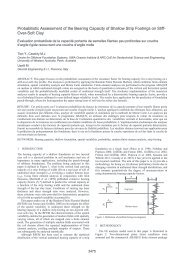
<strong>Improvement</strong> <strong>of</strong> s<strong>of</strong>t <strong>fat</strong> <strong>clay</strong> <strong>using</strong> <strong>rigid</strong> <strong>inclusions</strong> <strong>and</strong> <strong>vertical</strong> <strong>drains</strong>Amélioration d’une argile plastique molle par <strong>inclusions</strong> <strong>rigid</strong>es et <strong>drains</strong> verticauxKirstein J.F.BVT DYNIV GmbH; GermanyWittorf N.Ingenieurbüro Dr. Lehners und Wittorf; GermanyABSTRACT: In the case <strong>of</strong> a new road crossing in Germany with 1.5 to 7.0 m high embankments nearby the Danish borderparticularly s<strong>of</strong>t <strong>clay</strong>s were found 13 to 20 m deep below sea level. The undrained shear strength <strong>of</strong> the <strong>clay</strong> varied between 7 <strong>and</strong> 20kN/m². The water content was almost 100 % <strong>and</strong> the organic matter below 6 %. The consolidation coefficient C v < 0.3 m²/year ischaracteristics <strong>of</strong> a <strong>fat</strong> <strong>clay</strong> which requires a long time or tight spacing <strong>of</strong> <strong>vertical</strong> <strong>drains</strong> to consolidate. Due to stability risks, <strong>vertical</strong>wick <strong>drains</strong> were installed at a 0.5 m spacing in the part <strong>of</strong> the highest embankments, which were built in three load steps, each timewaiting for 60 to 80 % consolidation degree before loading the next step. Even <strong>using</strong> 600 kN/m woven geotextiles, a total <strong>vertical</strong>settlement <strong>of</strong> around 1.5 m <strong>and</strong> up to 27 cm horizontal deformation were measured throughout one year <strong>of</strong> monitoring. Thesedeformations were too high for the existing <strong>and</strong> running highway in the middle <strong>of</strong> the new projects. Therefore, full displacementconcrete columns (<strong>rigid</strong> <strong>inclusions</strong> system CMC) were installed up to 22 m deep with load transfer platforms installed on top theinlcusions. In order to improve the installation process <strong>of</strong> the <strong>rigid</strong> <strong>inclusions</strong>, additional <strong>vertical</strong> <strong>drains</strong> were installed in the s<strong>of</strong>t soilbefore the <strong>inclusions</strong>. Within the first two years, the area supported by the <strong>rigid</strong> inclusion experienced less than 2 cm <strong>of</strong> deformation, aproportionally small amount compared to the deformations recorded in the wick drain consolidation parts <strong>of</strong> the project.RÉSUMÉ : Pour un projet d’une nouvelle route sur des remblais de 1,5 à 7,0 m de hauteur en Allemagne près de la frontière danoise,des argiles particulièrement molles ont été trouvés de 13 à 20 m de pr<strong>of</strong>ondeur sous le niveau de la mer. La résistance au cisaillementde l'argile varie entre 7 et 20 kN / m². La teneur en eau est proche de 100% et la matière organique inférieure à 6%. Le coefficient deconsolidation Cv
Proceedings <strong>of</strong> the 18 th International Conference on Soil Mechanics <strong>and</strong> Geotechnical Engineering, Paris 2013Due to stability <strong>and</strong> settlement calculations the foundationworks took place according to the following sequence <strong>of</strong> works<strong>and</strong> according to the figure 2 below:1. Installation <strong>of</strong> <strong>vertical</strong> <strong>drains</strong> in different spacings froma one meter thick s<strong>and</strong> working platform.2. Preloading with three load steps with a distance <strong>of</strong> 30 msecurity <strong>and</strong> working space from the bridge <strong>and</strong>existing highway B5. (A)3. The measured consolidation settlements shown in figure8 fit with the given predictions according to figure 7.An additional strong woven geotextile layer <strong>of</strong> 600kN/m tensile strength between the embankment <strong>and</strong><strong>vertical</strong> <strong>drains</strong> had very little influence on the <strong>vertical</strong>inclinometer results with 27 cm <strong>of</strong> deformation asshown in figure 9.4. After waiting for 1.3 m settlement (figure 8) a part <strong>of</strong>the embankment <strong>and</strong> preload was temporarily rebuiltin order to install the controlled modulus ColumnsCMC. (B)5. The preload was brought back to the edge <strong>of</strong> thefoundation systems between CMC <strong>and</strong> <strong>vertical</strong> <strong>drains</strong>area in order to optimize the settlement behaviour.(C)6. Installtion <strong>of</strong> deep foundations for the bridge took placeon driven concrete piles with additional sleevessockets in the s<strong>of</strong>t soils.7. The CMC were installed between the driven pilesafterwards, free <strong>of</strong> vibrations.Figure 2. steps <strong>of</strong> consolidation <strong>and</strong> constructionThe working sequence with different steps was necessarybecause <strong>of</strong> stability calculations <strong>and</strong> the wide influence <strong>of</strong> thesettlements during the consolidation. The CMC brought thefollowing advantages:- short installation period to complete the project on time- the vibration free technique allows to work close to thepiles <strong>of</strong> the bridge- The settlements <strong>of</strong> the embankment support on CMCwith a stiff load transfer platform are compatible withthe bridge abutment2 SOIL-PARAMETERSAfter the first part <strong>of</strong> the soil investigations with several borings(BS) <strong>and</strong> cone penetration tests (CPT) it was clear that therewas a problem <strong>of</strong> stability <strong>and</strong> consolidation time due to thepresence <strong>of</strong> <strong>fat</strong> <strong>clay</strong> in the upper s<strong>of</strong>t soil layer. The project canbe modelled with two layers <strong>of</strong> s<strong>of</strong>t soils divided by a looses<strong>and</strong> layer in between. This reaches 13 m up to 22 m in thedeepest parts from the surface.The undrained shear strength c u in the s<strong>of</strong>t soil from theresults <strong>of</strong> shear vane tests multiplied with factors <strong>of</strong> 0.5 to 0.65are linked to the plasticity according to Bjerum st<strong>and</strong>ard DIN4094-4, Part 4 (Deutsche Institut für Normung 2002). In additonto borings, several laboratory testing ( water content, organicmatter <strong>and</strong> plasticity index ) as well as several load-settlementtests were performed.Figure 3. boring, cone penetration test <strong>and</strong> shear vane test in the detailarea bridge westThe vane tests showed an undrained shear strength <strong>of</strong> c u = 6to 8 kN/m² near the bridge <strong>and</strong> an undrained shear strength <strong>of</strong> c u= 12 to 20 kN/m² in other parts <strong>of</strong> the project. This was onemore reason to select a CMC foundation nearby the bridge inthe area <strong>of</strong> the lowest undrained shear strength.Following this decision <strong>and</strong> the results <strong>of</strong> soil investigation<strong>and</strong> laboratory the geotechnical engineers assumed an undrainedshear strength <strong>of</strong> c u = 12 kN/m² in <strong>vertical</strong> drain areas. Therepresentative soil parameters for the calculation <strong>of</strong>consolidation <strong>and</strong> stability in the project are given in thefollowing table.Table 1 . soil parameters for the calculation <strong>of</strong> consolidation <strong>and</strong>stability in the coloured drain areassoilproperties /soildensityγ k /γ k ’[kN/m 3]shearstrenghtφ’ k[grade]CohesionC’ ,k C u,k[kN/m²]ModulusE s,k[MN/m²]50-100kN/m²Consolidationcoefficientc v [m²/s]fill s<strong>and</strong> 18/10 30,0 --- 60 6,0*10 -1s<strong>of</strong>t soil, <strong>clay</strong>[top level]s<strong>of</strong>t soil, silttop level14/4 17,5 15 12 0,8 8,0*10 -915/5 20,0 10 12 0,8 2,0*10 -8s<strong>and</strong> 18/10 27,5 --- 25 2,5*10 -3s<strong>of</strong>t soil, silt(Bottomlevel)16/6 20,0 10 20 2,0 1,0*10 -73 SOILIMPROVEMENT TECHNIQUES3.1 Vertical <strong>drains</strong>Prefabricated <strong>vertical</strong> <strong>drains</strong> were installed in different spacingswith lengths between 15 m (corresponding to the conditions infigure 3) <strong>and</strong> 22 m in other parts <strong>of</strong> the project. It was necessary2514
Technical Committee 211 / Comité technique 211to pass the intermediate s<strong>and</strong>layer in order to place the <strong>vertical</strong><strong>drains</strong> in the glacial s<strong>and</strong> below the second layer <strong>of</strong> s<strong>of</strong>t soil.The small spacings in this project were justified by the steploading <strong>and</strong> the presence <strong>of</strong> <strong>fat</strong> <strong>clay</strong> in the upper layer <strong>of</strong> s<strong>of</strong>tsoil with special low permeability <strong>and</strong> corresponding primaryconsolidation coefficient.3.2 Controlled Modulus Columns CMCThe controlled modulus columns CMC are well adapted toinstallation in s<strong>of</strong>t soils. The full displacement auger acts as acasing <strong>and</strong> maitain the right borehole diameter over more thantwo meter length. Concrete pressure <strong>and</strong> adequate volume aremonitored <strong>and</strong> maintained throughout the concreting phase,which is very critical in very s<strong>of</strong>t soils. The typical pilingst<strong>and</strong>ards give a minimum limit <strong>of</strong> 15 kN/m² undrained shearstrength to use for cast-in-place-concrete.By the st<strong>and</strong>ard DIN EN 12699 (Deutsche Institut fürNormung 2001) above c u = 15 kN/m² the minimal distancebetween full displacing elements is linked to the undrainedshear strength <strong>of</strong> the soils. Critical distance is only relevantduring the concrete curing period.Compared to vibrating techniques, CMC are usually faster toinstall <strong>and</strong> can be performed in s<strong>of</strong>ter soils with lower undrainedshear strength. There are several references with CMCinstallationdirectly adjacent to freshly grouted CMC underc u < 15 kN/m² conditions. In this project the CMC have beenfirst successfully checked under conditions with the lowest c u -values by integrity tests <strong>and</strong> dynamic pile tests. Loads largerthan 500 kN could be tested with a factor <strong>of</strong> safety larger than 2FOS on the CMC, drilled into the glacial s<strong>and</strong> layer.On part <strong>of</strong> the project, the process <strong>of</strong> installing additionalCMCs close to nearby fresh CMC was improved through theinstallation <strong>of</strong> <strong>vertical</strong> <strong>drains</strong> in-between the CMC. Immediatelyafter the CMC installation the water starts to flow out <strong>of</strong> the<strong>vertical</strong> drain even at the top <strong>of</strong> the s<strong>and</strong>y working platform. Acontinuous flow for several hours up to one day <strong>and</strong> the volume<strong>of</strong> water collected show an efficient fast additionalconsolidation.Compared with other CMC areas the heave <strong>of</strong> the workingplatform <strong>and</strong> the excessive over-consumption <strong>of</strong> concrete,normally increasing with the thickness <strong>of</strong> s<strong>of</strong>tsoil, could bereduced by the additional intermediate <strong>vertical</strong> <strong>drains</strong>.Figure 5. 129 cm <strong>of</strong> settlements within ½ year <strong>of</strong> primary consolidationwith <strong>vertical</strong> <strong>drains</strong> spacing <strong>of</strong> 0.75 mThe stability calculations are based on undrained shearstrength c u <strong>and</strong> required to build the embankment in three steps<strong>of</strong> loading with berms <strong>and</strong> twice waiting for the sufficientdegree <strong>of</strong> consolidation necessary. According to (Chaumeny,Kirstein <strong>and</strong> Varaksin 2008) the shear strength was calculated<strong>using</strong> the following relation to the degree <strong>of</strong> consolidation:τ = U (σ tan φ'+c) + (1-U) c u (1)U: degree <strong>of</strong> consolidationσ: total load at a given depthφ': internal friction anglec: final drained cohesionc u : undrained shear strengthFigure 6. stability calculation <strong>of</strong> three loading steps <strong>and</strong> controlcalculation <strong>of</strong> the final situationFor this project c = c u in formula (1) as improvement Δc uwas added to the basic c u value in the stability calculations.Δc u = U σ tan φ' (2)Figure 7. settlement calculations with the three load stepsFigure 4. installation <strong>of</strong> CMC combined with <strong>vertical</strong> <strong>drains</strong> <strong>and</strong> porewateron the platform4 CALCULATIONS AND PREDICTIONS4.1 Consolidation <strong>and</strong> stability calculations in the areasreceiving <strong>vertical</strong> <strong>drains</strong>Initially, a total settlement <strong>of</strong> 1.29 m was calculated in the areawest <strong>of</strong> the bridge. The time-settlement curves for both primary<strong>and</strong> secondary consolidation are shown below on figure 5.Field measurements <strong>and</strong> the stability analysis in finalconfiguration based on φ', c <strong>and</strong> porewater pressure were ingood agreement with the calculations <strong>using</strong> the improvedundrained shear strength.4.2 Controlled Modulus Columns CMCDue to the presence <strong>of</strong> very s<strong>of</strong>t soils, the CMC are designed totake the full load <strong>of</strong> the embankment, neglecting the small loadbearing capacity <strong>of</strong> the soil in between the <strong>inclusions</strong>. With500 kN characteristic load per CMC, the calculated settlementat the top <strong>of</strong> each CMC is very similar to the settlement <strong>of</strong> thepiles under the bridge.2515
Proceedings <strong>of</strong> the 18 th International Conference on Soil Mechanics <strong>and</strong> Geotechnical Engineering, Paris 2013Nevertheless, below the embankment, there is no concrete slabor <strong>rigid</strong> structure like for the foundation <strong>of</strong> the bridge.Reinforced earth with galvanized steel was designed to hold thelarge horizontal forces <strong>of</strong> active earth pressure. Because <strong>of</strong> thelarge geotextile deformations during the consolidation period, asshown in the following monitoring results, the decision wasmade to use a stronger more <strong>rigid</strong> construction with nearly nodeformation. Compared with plastic geotextiles, the steel gridmaterial has only very small elastic deformations, <strong>and</strong> as aresult limiting the horizontal deformations <strong>of</strong> the embankment.Through the addition <strong>of</strong> some gravel in parts <strong>of</strong> the s<strong>and</strong>y loadtransfer platform LTP, the friction between LTP <strong>and</strong> CMC wasgreatly increase <strong>and</strong> nearly no deformation was necessary tomobilize the friction <strong>of</strong> the LTP.5.2 Controlled Modulus Columns CMCSeveral measurement systems were installed between the CMC<strong>and</strong> the reinforced earth in the load transfer platform. Theinstruments show an almost perfect full stress concentration <strong>of</strong>the load on the CMC <strong>and</strong> less than one centimetre <strong>of</strong> horizontaldeformation. Figure 10 shows the cross section <strong>and</strong> the 5<strong>vertical</strong> deformation measurements over a period <strong>of</strong> 2 years.The horizontal inclinometer was laid across six marked CMCcolumns(figure 1 <strong>and</strong> figure 9). A settlement <strong>of</strong> one centimetre<strong>of</strong> the top <strong>of</strong> the CMCs <strong>and</strong> two centimetres in-between CMC inthe reinforced earth steel construction were measured. Therewas a good agreement between the calculated values <strong>of</strong> thesettlement <strong>and</strong> the results <strong>of</strong> the monitoring.5 MONITORING RESULTS5.1 Wick <strong>drains</strong>Figure 10. horizontal inclinometer results with arround 1 cm <strong>of</strong> CMCsettlements <strong>and</strong> 2 cm <strong>of</strong> reinforced earth settlementsFigure 8. measurement at the settlement plates SP 9 und SP10.6 SUMMARY AND CONCLUSIONSS<strong>of</strong>t <strong>and</strong> <strong>fat</strong> <strong>clay</strong> were found at the B5 / B202 road crossing.Additional soil investigations <strong>and</strong> laboratory tests wereperformed to be able to complete a proper design, regardingstability <strong>and</strong> consolidation time.Oedometer consolidation tests allowed to precisely predict themovements during the consolidation processes that wereaccelerated by the use <strong>of</strong> <strong>vertical</strong> <strong>drains</strong> at different spacings.Large deformations <strong>of</strong> up to 1.5 m <strong>of</strong> settlements <strong>and</strong> 27 cm <strong>of</strong>horizontal displacement were experience <strong>and</strong> closely match thecalculations <strong>and</strong> show that it was the right decision not to placethe highest embankment directly on the s<strong>of</strong>test soil beside thebridge over the running traffic on the highway B5.Vibration free CMC in combination with reinforced earthallowed to construct this high embankment with less than twocentimetre differential settlements to the piled bridge.With a careful planning <strong>of</strong> the work within the overallconstruction schedule, detailed design combined with anextensive monitoring program, economic soil improvementtechniques can be combined with deep foundations in oneproject even on very s<strong>of</strong>t soil can be treated successfully.7 REFERENCESFigure 9. <strong>vertical</strong> inclinometer results at the 7 m high damm with <strong>drains</strong><strong>and</strong> 600 kN/m vowen geotextileThe measured settlements during the consolidation process infigure 8 follow very closely the predictions shown in figure 7.An additional strong geotextile layer <strong>of</strong> 600 kN/m tensilestrength between the embankment <strong>and</strong> the <strong>vertical</strong> <strong>drains</strong> had27 cm <strong>of</strong> deformation measured with <strong>vertical</strong> inclinometers.DIN Deutsches Institut für Normung, 2002, DIN 4094-4: Subsoil –field testing – part 4 : Field vane test.DIN Deutsches Institut für Normung, 2001, DIN EN 12699: Execution<strong>of</strong> special geotechnical work - Displacement piles; German versionJ-L Chaumeny, J.F.Kirstein, S. Varaksin, 2008, An experience <strong>of</strong>consolidation <strong>of</strong> extremly s<strong>of</strong>t mud for one <strong>of</strong> Europe’s largestprojects “The AIRBUS A-380” factory in Hamburg, Glasgow.2516