You also want an ePaper? Increase the reach of your titles
YUMPU automatically turns print PDFs into web optimized ePapers that Google loves.
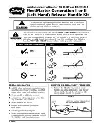
5. Install a 1/2˝ I.D. roller (ITEM 7) in cam anchor hole(see Figure 5).Figure 7Figure 56. Assemble a 1/2˝ I.D., 2 1 ⁄4˝ O.D. washer (ITEM 8) overthe roller, then pass the 1/2˝ bolt (with the redthread sealant) through the washer, roller and intothe casting. Tighten securely.NOTE: When installing washers (ITEM 8), therounded edge of the washer must always face thecam plate (see Figure 6).Figure 67. Pull the release handle and check for free movement.8. Place a 1/2˝ I.D., 2 1 ⁄4˝ O.D. washer (ITEM 8) betweenthe cam and plunger.9. Insert a 1/2˝ I.D. roller over the washer (in the camprofile).10. Install another 1/2˝ I.D., 2 1 ⁄4˝ O.D washer (ITEM 8)over the roller, then pass a 2˝ long, 1/2˝ diameterbolt through the assembly into the threaded hole ofthe plunger. Tighten securely, then loosen until thetop washer spins freely.11. Pull the release handle, remove the helper block andcheck for ease of operation.12. Using a 3/8˝ square deep well socket, securely tightenthe set screw (ITEM 3) in the plunger (see Figure 7 above).LEFT HAND (ROAD SIDE) RELEASE:NOTE: On top plates manufactured before May 1, 1979,torch off casting lip approximately 1 inch from castingrib (see Figure 3, on Page 2).1. Install a 9/16˝ I.D. washer over the open end of thehandle, then pass the open end of the release handlethrough guide hole (C) toward the outside of the topplate.2. Inspect the cam (ITEM 6L) for burrs or rough edgesin the cam profile. Remove as required.3. Lube the cam profile and pivot holes with a lightgrease, then insert the “S” bend of the handle intothe small hole in the cam plate.4. Position cam plate on the casting with the large holein cam plate in line with the top cam anchor hole (D).5. Install a 1/2˝ I.D. roller (ITEM 7) in cam anchor hole.6. Assemble a 1/2˝ I.D., 2 1 ⁄4˝ O.D. washer (ITEM 8) overthe roller, then pass the 1/2˝ bolt (with the redthread sealant) through the washer, roller, and intothe casting. Tighten securely.NOTE: When installing washers (ITEM 8 AND ITEM41), the rounded edge of the washer must alwaysface the cam plate (see Figure 6 at left).7. Pull the release handle and check for free movement.8. Place a 1/2˝ I.D., 2 5 ⁄8˝ O.D. washer (ITEM 41)between the cam and plunger.9. Insert a 1/2˝ roller over the washer (in the cam profile).10. Install another 1/2˝ I.D., 2 5 ⁄8˝ O.D. washer (ITEM 41)over the roller, then pass a 2˝ long, 1/2˝ diameterbolt through the assembly into the threaded hole ofthe plunger. Tighten securely, then loosen until thetop washer spins freely.11. Pull release handle, remove helper block and checkfor ease of operation.12. Using a 3/8˝ square deep well socket, securely tightenthe set screw (ITEM 3) in plunger (see Figure 7).13. On some models, there could be interferencebetween the washers (ITEM 41) and the fifth wheelcasting when the cam is in the locked position.When the fifth wheel is locked, the washers must befree to spin. If the washers contact the casting, grindthe casting at the point of interference shown by thearrow in Figure 8, until the washers are free to spin.3
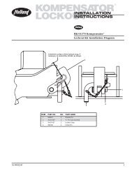
ADJUSTING WEDGE INSTALLATION1. Put release handle in the closed position.2. Coat the threads of the Allen head cap screw (ITEM13) with Never-Seez and install through the holelocated in the throat of the casting.3. Install compression spring (ITEM 11) over cap screw.4. Next, slide wedge (ITEM 12) along plunger,compress spring and install the 5/8˝ locknut (ITEM14), tighten the cap screw with a 1/2˝ Allen wrenchuntil nut is flush with end of bolt (see Figure 8).substitute lubricant.) Lubricate gear teeth with a lightgrease.7. Place the hinged lock into position (see Figure 10).Drive the lock pin (ITEM 17) through the top plateand pin hole of the hinged lock. Secure with cotterpin (ITEM 18).NOTE: If casting is equipped with lock pin bushings,lock pin (ITEM 32) and roll pin (ITEM 30) must be used.Figure 10Figure 8LOCK INSTALLATION1. Pull release handle into the unlocked position.2. Install green spring through large hole in the throatof the casting.3. Lubricate all contact surfaces of sliding lock (ITEM16A). With large counterbore down, slide tail of lockthrough spring and compress spring until lock isbeyond the plunger.4. Keeping hands away from moving parts, moverelease handle to the closed position.5. Now, push the sliding lock forward and insert a 1˝spacer between the lock and plunger (see Figure 9).6. Coat the lock pin hole in hinged lock (ITEM 16B)with Never-Seez. (This is vital. DO NOT use anyLOCK ADJUSTMENT1. Close the locks, using a <strong>Holland</strong> TF-TLN-1000 LockTester. Operation of tester is described in <strong>Holland</strong>publication <strong>XL</strong>-FW130. When operating properly, theplunger (ITEM 2) will slide freely behind the hingedlock (ITEM 16B) (see Figure 11).Figure 11Figure 92. Close the locks (using the lock tester), then, using aratchet with a 1/2˝ Allen wrench, tighten theadjustment screw (ITEM 13) in the throat of the topplate by turning clockwise until tight.3. Now loosen (turning counterclockwise) 1 1 ⁄2 turns.The locking mechanism is now properly adjusted.4. Check operation by locking and unlocking severaltimes.NOTE: If top plate does not operate properly, DONOT USE IT. Repeat the above procedures or contactyour local <strong>Holland</strong> Representative for assistance.4
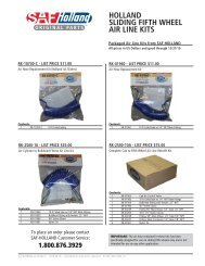
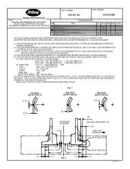
9 10FOR LEFT HAND REL.135R478887AD6R9876L5L104074041412 11132BCMODELS EQUIPPED with29 LOCK PIN30 BUSHINGS3132332<strong>01</strong>922211537ANOT INCLUDEDIN REBUILD KIT37B37C3536MODELS EQUIPPED withSECONDARY LOCKS23 24 2538262728ACCESSORIES16A343916B17 186NO.NO.ITEM PART NO. REQ’D. PART NAME ITEM PART NO. REQ’D. PART NAME1 XB-1007 (Red) 1 Comp. Spring 1 5 /8˝ O.D. x 5˝2 XA-1119 1 Plunger3 XB-15 1 Set Screw4 XB-T-49 1 Plain washer 1/2˝5L RK-1117-1L 1 Left hand release handle(Item No. (4) must be installedon handle for complete assy.)5R RK-1117-1 1 Right hand release handle(Item No. (4) must be installedon handle for complete assy.)6L XA-1118-2-L 1 Left hand cam plate6R XA-1118-1 1 Right hand cam plate7 XA-1029 2 Roller8 XB-1030 3 (For right hand) washer -1/2˝ I.D. x 2 1 /4˝ O.D.1 (For left hand) washer9 XB-2083 1 Hex hd. screw 1/2˝-20 x 1 3 /4˝with locking patch10 XB-1031 1 1/2˝-20 x 2˝ Hex hd. cap screw11 XB-403 1 Spring12 XD-3123-1 1 Lock adjusting wedge13 XB-09407 1 5/8˝-11 x 3 3 /4˝ Soc. hd. screw14 XB-09174 1 5/8˝-11 Locknut15 XB-1006 (Green) 1 Comp. spring 1 1 /4˝ O.D. x 5˝16A XA-1102 1 Lock set16B17 XA-1<strong>01</strong>6 1 Hinged lock pin18 XB-5 1 Cotter pin 1/4˝ x 2˝19 XA-1621 1 Lock guard20 XB-1044 1 Torsion spring21 XA-1055 1 Pin22 XB-16 2 Cotter pin 1/8˝ x 1˝*23 XA-1668 1 Safety lock block*24 XB-NRJ-34-F 1 Jam nut*25 XA-1674 1 Safety release arm*26 XB-V-919 1 1/2˝ diameter steel ball*27 XB-V-932 1 Compression spring*28 XB-V-1025 1 Set screw 5/8˝ - 18**29 XB-767-C 1 Grease fitting**30 XB-21-S-250-1875 1 Roll pin**31 XA-279 1 Lock pin bushing**32 XA-1<strong>01</strong>6-C 1 Hinged lock pin**33 XA-278 1 Lock pin bushing*34 XB-H-38 2 Grease fitting*35 XA-2<strong>01</strong>6 2 Bracket pin*36 XB-21-S-375-1750 2 Roll pin*37A XB-1604-5 2 Rubber bushing (for fifth wheelswheels manufactured prior to 5/82)*37B XB-0<strong>01</strong>1-1 2 Rubber bushing (no longeravailable - order RK-03809bushing & riser kit or refer to ServiceBullletin No. 16 for instructions)*37C XB-0<strong>01</strong>1-2 2 Rubber bushing (for fifth wheelsmanufactured after 6/87)38 TF-<strong>01</strong>10 1 Kingpin gage39 TF-TLN-50<strong>01</strong> 1 Kingpin lock tester40 XB-02846 2 Washer (left hand only)1/2˝ I.D. x 2 5 /8˝ O.D.* Not included in Rebuild Kit** Additional parts included in RK-62<strong>01</strong>1 & RK 62<strong>01</strong>2 Rebuild Kits (Kits contain Item No. 32 in place of Item No. 17)
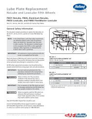
GENERAL INFORMATION1. All fifth wheel maintenance, adjustment andrebuilding must be performed by a qualified personusing proper tools and safe procedures. For moreinformation, refer to <strong>Holland</strong> Publication <strong>XL</strong>-FW303“Fifth Wheel Maintenance Procedures.”2. Do not modify or add to the product.3. Use only genuine <strong>Holland</strong> parts.4. Wear safety goggles during installation, removal andrebuilding.5. Never strike any part of the item with a steelhammer.6. Do not weld on this product without writtenpermission from the factory.7. Observe standard precautions when lifting.8. Refer to <strong>Holland</strong> Publication <strong>XL</strong>-FW340 fordescription and instructions for <strong>Holland</strong> TF-TLN-50<strong>01</strong>Kingpin Lock Tester.9. Do not deviate from these instructions. Any changesor deviations will void all warranties, expressed orimplied, unless written consent is first obtained fromthe factory.10. Check to see that all parts included in the kit areenclosed in the box.WARNINGThis equipment must notbe used or maintained ina careless manner.These products are covered by <strong>Holland</strong>’s CommercialProducts Warranty. <strong>Holland</strong> reserves the right, withoutgiving prior notice, to change specifications anddimensions as designs are altered or improved.7
HOLLAND USA, INC.1950 Industrial Blvd. • P.O. Box 425 • Muskegon, MI 49443-0425Phone 888-396-65<strong>01</strong> • Fax 800-356-3929www.thehollandgroupinc.comCopyright @ June 2004 • The <strong>Holland</strong> <strong>Group</strong>, <strong>Inc</strong>.<strong>Holland</strong> USA, <strong>Inc</strong>. Facilities:Dumas, AR Warrenton, MO<strong>Holland</strong>, MI Wylie, TXMuskegon, MI<strong>Holland</strong> International, <strong>Inc</strong>.<strong>Holland</strong>, MIPhone: 616-396-65<strong>01</strong>Fax: 616-396-1511<strong>Holland</strong> Hitch of Canada, Ltd.Woodstock, Ontario • CanadaPhone: 519-537-3494Fax: 800-565-7753<strong>Holland</strong> Equipment, Ltd.Norwich, Ontario • CanadaPhone: 519-863-3414Fax: 519-863-2398<strong>Holland</strong> Hitch of Canada, Ltd.Surrey, British Columbia • CanadaPhone: 604-574-7491Fax: 604-574-0244Ph: 888-396-65<strong>01</strong> Fax: 800-356-39298