TB 1534 d 50 GC182N5 ME3066L3
TB 1534 d 50 GC182N5 ME3066L3
TB 1534 d 50 GC182N5 ME3066L3

You also want an ePaper? Increase the reach of your titles
YUMPU automatically turns print PDFs into web optimized ePapers that Google loves.
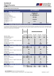
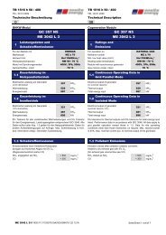
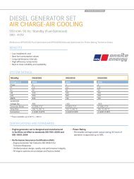
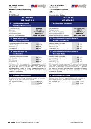
<strong>TB</strong> <strong>1534</strong> d <strong>50</strong>/400TM-02.02.2009Technische BeschreibungD<strong>TB</strong> <strong>1534</strong> d <strong>50</strong>/400TM-02.02.2009Technical DescriptionGBBHKW-ModulGC 182 N51 Leistungsdaten und1SchadstoffemissionenCogeneration ModuleGC 182 N5ME 3066 L 3 ME 3066 L 3Ratings and EmissionsFür den Betrieb mitERDGASFor operation onNATURAL GASMethanzahlMZ ≥ 70Methane numberMZ ≥ 70Heizwert min. Hu=10kWh/m n ³ Min. low heat value (LHV) Hu=10kWh/m n ³Heizwassertemperatur HW90/70°C Heating water temperatureHW90/70°CModul mit Synchrongenerator 400V, 3Ph, <strong>50</strong>Hz Module with synchronous generator 400V, 3Ph, <strong>50</strong>HzGemischkühler, intern 70°C Gas mixture cooler, intern70°C1.1 Dauerleistung im1.1 Continuous Operating Data inNetzparallelbetriebGrid Parallel ModeElektrische Leistung am Generator(nicht überlastbar)Wärmeleistung 279Thermal outputEnergieeinsatz 520 kW Total energy input182kW elkW thElectrical output of generator(no overload capacity)182 kW el279 kW th520 kW1.2 Dauerleistung im1.2 Continuous Operating Data inInselbetriebIsolated ModeElektrische Leistung am Generator(10% überlastbar)Wärmeleistung 254Thermal outputEnergieeinsatz 472 kW Total energy input164kW elkW th8% Toleranz für alle vorstehenden Wärmeleistungen und 5%Toleranz für den Energieeinsatz. Leistungsangaben entsprechendISO 3046. Alle Daten außer unter Kap. 1.2 gelten für denNetzparallelbetrieb. Daten für andere Aufstellbedingungen aufAnfrage. Max. Scheinleistung in kVA, bzw. Nennstrom entspr.Generator-Typenleistung.Electrical output of generator(overload capacity 10%)164 kW el254 kW th472 kW8% tolerance for thermal outputs and 5% tolerance for total energyinput listed. Performance data in accordance with ISO 3046. Alldata apply to grid parallel operation except those in 1.2. Data forsite operating conditions other than those mentioned, on request.Max. reactive power in kVA, resp. nominal current acc. to nominaloutput of the generator.1.3 Schadstoffemissionen1.3 Pollutant EmissionsEmissionswerte nach Oxidations-Katalysator, bezogen auftrockenes Abgas mit 5% O 2 . (Abgasvolumenstrom siehe 3.5)Emission values after oxidation catalytic converter, related to dryexhaust gas with 5% O 2 . (for exhaust gas volume flow see 3.5)NO x , angegeben als NO 23< <strong>50</strong>0 mg/m nNO x , stated as NO 23< <strong>50</strong>0 mg/m nCO3< 300 mg/m n CO3< 300 mg/m nME 3066 L 3 /1<strong>50</strong>0/10:1/70/9070/OxK/<strong>50</strong>0/GMK70/ LD 155A Seite/Sheet 1 von/of 7
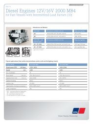
<strong>TB</strong> <strong>1534</strong> d <strong>50</strong>/400TM-02.02.2009Technische BeschreibungD<strong>TB</strong> <strong>1534</strong> d <strong>50</strong>/400TM-02.02.2009Technical DescriptionGB2 Aufbau/Lieferumfang2• Generator am Motor angeflanscht•• Elastische Kupplung, Verbindungsglocke mit Serviceöffnung, •Austausch des Kupplungsreifens ohne Verschiebung vonMotor oder Generator möglich• Motor-Generator-Einheit mit elastischen,•schwingungsdämpfenden Elementen auf Grundrahmen• Wärmetauscher-, Abgaseinheit mit angebauter Lambda- •Sonde, Katalysator und Schalldämpfer komplett verrohrt imGrundrahmen• Grundrahmen schwingungsgedämpft aufgestellt•• Der Liefergegenstand entspricht der EG-Maschinenrichtlinie •und den deutschen Vorschriften/Normen.Bei Verwendung des Liefergegenstandes im Ausland istMTU nicht für die Einhaltung der gesetzlichen und sonstigenVorschriften/Normen am Verwendungsort verantwortlich.Design Principles/Scope of SupplyThe generator is flange-mounted on the engineFlexible coupling, interconnecting bell housing, serviceopening so that replacement of the rubber element can beachieved without displacing engine or generatorThe genset is connected to the base frame by means ofelastic vibration damping elementsThe heat exchanger and exhaust gas unit with its integratedlambda probe and catalytic converter and silencer are fullypiped and mounted in the base frameThe base frame is installed on vibration dampersThe deliveries comply with the EC Machinery Directive andthe German Industrial Standards and Regulations.If the delivered goods are to be used outside Germany,MTU is not responsible for legal and other requirements/regulations applicable at the place of installation.2.1 Motor und Zubehör2.1 Engine plus AccessoriesOtto-Gas-Motor (Magermotor) E 3066 L 3 Otto-gas-engine (lean-mix operating) E 3066 L 3Anordnung/Zylinderzahl R 6 Cyl. arrangement, no. of cyl.R 6Bohrung/Hub 130/155 mm Bore/stroke 130/155 mmDrehzahl1<strong>50</strong>0 1/minSpeed1<strong>50</strong>0 1/minMittlere Kolbengeschwindigkeit7,8 m/sMean piston speed7,8 m/sVerdichtungsverhältnis 10:1Compression ratio 10:1Mittlere effektiver Druck 12,3 bar Mean effective pressure12,3 barStandardleistung nach ISO 3046,Standard power acc. to ISO 3046,190 kW mech(nicht überlastbar)*(no overload capacity)*190Spez. Volllastverbrauch(Toleranz 5%)Gasverbrauch(z.B. bei Hu=10kWh/Nm 3 )Schmierölverbrauch(ohne Gewähr, bei Nennlast)2,74 kWh/kWh mech52,0 m 3 /h* Überlastung ist durch geeignete externe Regeleinrichtungen*(z.B. elektronische Leistungsregelung) zuverlässig zu verhindern.Specific full-load consumption(tolerance 5%)Gas consumption(based on LHV=10kWh/m 3 )0,20 g/kWh mechLube oil consumption(not guaranteed, at rated load)kW mech2,74 kWh/kWh mech52,0 m 3 /h0,20 g/kWh mechOverload must reliably be avoided by means of suitable externalcontrol systems (e.g. electronic output power control).• Kurbelgehäuse mit Einzelzylinderköpfe•• Nasse Zylinderlaufbüchsen•• Trockenfilterpatronen mit Wartungsanzeiger•• Gaszufuhr über Venturimischer•• Abgasturbolader,•wassergekühltes Turbinengehäuse• Gemischkühler•• Zwei Flammschutzfilter•• Isoliertes Abgassammelrohr•• Rechnergesteuerte Hochspannungs-Kondensator-•Zündanlage mit einer Zündspule je Zylinder• Drehzahl- und Leistungsregelung durch elektronischen•Drehzahlregler mit elektrischem Stellglied aufGemischdrosselklappe wirkend• Motorkühlung im geschlossenen Wasserkreislauf,•Umwälzpumpe mit Drehstrommotor, Sicherheitsüberdruckventilund Membranausdehnungsgefäss• Zahnradpumpe für Druckölschmierung,•Ölkühler und Ölfilter• Automatische Schmierölnachfülleinrichtung•• Ölwanne, ohne Anheben des Motors demontierbar•• Schubtriebstarter 24 V•Crank case with single cylinder headsWet-type cylinder linersDry filter cartridge with maintenance indicatorGas supply through venturi mixerExhaust powered turbocharger,with water cooled turbine casingGas mixture coolerTwo flame protection filtersInsulated exhaust manifoldElectronic high-voltage capacitor ignition system with oneignition coil per cylinderElectronic speed governor for speed and power outputcontrol, with electric actuator to operate the gas mixturethrottle valveClosed circuit engine cooling system, circulation pump withthree-phase AC motor, safety pressure relief valve anddiaphragm-type expansion tankGear pump for lubrication,oil cooler and oil filterAutomatic lubrication oil top-up systemOil sump, removable without lifting the engineSliding gear starter 24 VME 3066 L 3 /1<strong>50</strong>0/10:1/70/9070/OxK/<strong>50</strong>0/GMK70/ LD 155A Seite/Sheet 2 von/of 7
<strong>TB</strong> <strong>1534</strong> d <strong>50</strong>/400TM-02.02.2009Technische BeschreibungD<strong>TB</strong> <strong>1534</strong> d <strong>50</strong>/400TM-02.02.2009Technical DescriptionGB2.2 Generator2.2 GeneratorSelbstregelnder, bürstenloser Innenpol-Synchrongenerator miteingebauter Erregermaschine, Spannungs- und Cos -Regler.Ausführung nach VDE0530, Funkstörgrad N, Isolationsklasse H,Erwärmungsklasse F (20K Temperaturres.), oberwellenarmeAusführung.Self-regulating, brushless revolving-field synchronous generatorwith built-in exciter, voltage and cos regulator, designed to VDE0530, radio interference class N, insulation class H, temperatureriserating F (20 K temperature reserve), low-harmonic design.TypenleistungSpannung276 kVA400 VRatingVoltage276 kVA400 VFrequenz<strong>50</strong> HzFrequency<strong>50</strong> HzDrehzahl 1<strong>50</strong>0 1/min Speed 1<strong>50</strong>0 1/minWirkungsgrad (Volllast)95,8 %Efficiency (100% load)95,8 %bei Cos * 1 at Cos* 1Ständerschaltung Stern Stator connectionStarUmgebungstemperatur max. 40 °C Max. ambient temperature. 40 °CSchutzart IP 23 Protection class IP 23*) Der cos-phi muss im gesamten Leistungsbereich zwischen 1,0 und 0,8liegen. Nur induktive Blindleistungsabgabe zulässig (übererregt).*) Cos-phi has to be in the whole power range between 1,0 and 0,8.Only inductive reactive power admissible (over-erected).2.3 Wärmetauschersystem2.3 Heat Exchanger SystemWärmerückgewinnung aus Motorblock/AbgasHeat recovery from engine block/exhaust gas• Abgaswärmetauscher im Kühlwasserkreis integriert• Exhaust gas heat exchanger integrated in thecooling water system• Gemischkühler im Heizwasserkreis integriert• Mixture cooler integrated in the heating water system• Plattenwärmetauscher Motorkühl-/Heizwasser•• Heizwasseranschlüsse stirnseitig•• Wärmetauscher und Abgasschalldämpfer isoliert•• Wärmetauscher und Druckbehälter nach•DGRL 97/23 EG ausgelegt.Plate heat exchanger engine cooling-/heating waterHeating water connections at the end faceHeat exchangers and exhaust gas silencer insulatedHeat exchangers and pressure vesselsdesigned per DGRL 97/23 EG.Motorkühlung (Motorblock mit Schmieröl)Engine Cooling (Engine Block with Lube Oil)Wärmeleistung (Toleranz 5 %) 118 kW Thermal output (5% tolerance) 118 kWKühlwassertemperatur Ein-/Austritt 82/88 °C Cooling water temperature, in-/outlet82/88 °CAbgaswärmetauscherWärmeleistung (Toleranz 5 %) 138 kW Thermal output (5% tolerance)Abgastemperatur Ein-/Austritt 524/120 °C Exhaust gas temperature, in-/outletKühlwassertemperatur Ein-/Austritt 88/94 °C Cooling water temperature, in-/outletDruckverlust abgasseitig < 10 mbar Pressure loss on exhaust side< 10 mbarWerkstoff Rohre 1. 4571 Tube material1. 4571Werkstoff Abgas-Kopf Ein-/Austritt 1.4828 oder 1.4571 Exhaust gas header material, in-/outlet 1.4828 or 1.4571Werkstoff WassermantelrohrST 35 Water jacket material ST 35GemischkühlerExhaust Gas Heat ExchangerMixture Cooler138 kW524/120 °C88/94 °CWärmeleistung (Toleranz 5 %) 24 kWThermal output (5% tolerance)Heizwassertemperatur Ein-/Austritt 70/72 °C Heating water temperature, in-/outletPlattenwärmetauscherPlate Heat Exchanger24 kW70/72 °CWärmeleistung (Toleranz 5 %) 256 kWThermal output (5% tolerance)256 kWKühlwassertemperatur Ein-/Austritt 94/82 °C Cooling water temperature, in-/outlet94/82 °CHeizwassertemperatur Ein-/Austritt 72/90 °C Heating water temperature, in-/outlet 72/90 °CME 3066 L 3 /1<strong>50</strong>0/10:1/70/9070/OxK/<strong>50</strong>0/GMK70/ LD 155A Seite/Sheet 3 von/of 7
<strong>TB</strong> <strong>1534</strong> d <strong>50</strong>/400TM-02.02.2009Technische BeschreibungD<strong>TB</strong> <strong>1534</strong> d <strong>50</strong>/400TM-02.02.2009Technical DescriptionGB2.4 Gasversorgung2.4 Gas SupplyGasregelstrecke lose mitgeliefert, mit folgenden Komponentenzugelassen nach Gasgeräterichtlinie 90/356/EWG• Gasfilter• Gas filter• zwei Magnetventile (oder Doppelmagnetventil)• two solenoid valves (or double solenoid valve)• Ventildichtheitskontrolle• valve leakage monitor• Druckregler (Nulldruckregler)• pressure regulator (zero pressure regulator)• Gasregelventil für Lambda-Regelung• gas regulating valve for lambda control• flexible Edelstahlschlauchleitung• flexible stainless steel hose2.5 Modulsteuerung und2.5 Module Control andÜberwachungseinrichtungenMonitoring SystemModulsteuerung ohne Leistungsteil als Funktionseinheit am Modulangebaut und verkabelt, mit folgenden Komponenten:• Komplette Modulsteuerung über RPS (Rechnerprogrammierbare•Steuerung) für die BetriebsartNetzparallel und Netzersatz* ) mit Start-Stopp-Ablauf undÜberwachung durch Analoggeber für Öldruck,Kühlwassertemperatur nach Motor u. Abgas-WT,Heizwassertemperatur, Abgastemperatur vor Turbolader u.im Kat (sofern im Lieferumfang), Ansauglufttemperatur,Gemischtemperatur, Generatorwicklungstemperatur,Drehzahl sowie Kontaktgeber für Kühlwasserdruck min.,Sicherheitstemperaturbegrenzer max., Schmierölniveaumin./max., Gasdruck min. u. GasdichtigkeitGas regulation line delivered loose, components approvedper Directive for Gas Components 90/356/EWGModule control (excluding power part) attached to the module asfunctional unit and ready wired, with the following components:Complete computer control for the operating modes gridconnected and isolated operation* ) , start/stop control;analogue monitoring of oil pressure, cooling watertemperature after engine and after exhaust gas heatexchanger, heating water temperature, exhaust gastemperature in front of turbocharger and in the catalyst (ifincluded in scope of supply), intake air temperature gasmixture temperature, generator coil temperature, speed; andfor binary monitoring of cooling water pressure min., safetytemperature limit, oil level min./max., gas pressure min., gastightness of valve• Synchronisierung, Netz- u. Generatorüberwachung•(ohne Erdschlussüberwachung)• Leistungsregelung für Warmlauf, Fest- und Gleitwert mit •Rampenfunktion bei Start- u. Stopp, sowieLeistungsreduktion bei zu hoher Ansauglufttemperatur bzw.Gemischtemperatur oder bei klopfender Verbrennung• Lambdaregelung•• Klopfregelung (Option)•• Heizwassertemperatur Regelung (Option)•• Steuerfunktionen zur Ansteuerung des Generatorschalters •und bei Netzersatz (Option) zur Ansteuerung eineszusätzlichen Netzschalters (nur bei einer einfachenEinmodulanlage), Hilfsantriebe, Notkühler (Option) undModulvorwärmung (Option) über potentialfreie KontakteSynchronisation, grid- and generator monitoring(without earth fault)Power output control for engine warm up, fixed or variableset point with ramp function for start and stop, automaticoutput reduction at excessive intake air temperature resp.gas mixture temperature, or if knocking occursLambda controlKnocking control (option)Heating water control (option)Control functions for triggering of the generator breaker andfor isolated operation (option) for triggering of the additionalcircuit breaker (only for single-module plant), auxiliary drives,backup cooler (option) and module preheater (option) via drycontacts.• Betriebs u. Sammelstörmeldungen über potentialfreie•Kontakte• Potentialfreie Eingänge für Fernstart, Festwertregelung•(Option) und Gleitwertregelung (Option) sowieNetzersatzstart (Option)• Modulhilfsantriebesteuerungen für Kühlwasserpumpe,•Schmierölnachfüllung, Drehzahlregelung, Zündung,Gasstraße, Batterieladegerät, Anlasser• Bedien- u. Anzeigetableau für Betriebswerte,•Störmeldungen, Statusmeldungen, Einstell- u.Regelparameter• Schlüsselschalter für Sicherheitsabstellung•• Option: Schnittstelle für Datenübertragung zur Anbindung an •eine Leittechnik (TTY mit Protokoll 3964R, oder Profibus DP,oder Mod-Bus RTU)*) Netzersatz- und Notstrom (Option); bei mehr als einem Modul/Aggregat isteine übergeordnete Leittechnik erforderlichDry contacts for operation and fault signalsDry contacts for remote start, fixed set point control(optional) and variable set point control (optional), isolatedmode (optional)Aux. drives control of the module only for cooling waterpump, lube oil top up device, speed control, ignition, gas line,battery charger, starterOperation and indication panel for operating parameters,fault signals, status signals, set points, and controlparametersKey switch for safety stopOption: Interface for data communication with a supervisorycontrol (TTY with protocol 3964R, or profibus DP, or modbusRTU)*) Isolated and emergency power operation (option); with more than onemodule/genset a supervisory control is requiredME 3066 L 3 /1<strong>50</strong>0/10:1/70/9070/OxK/<strong>50</strong>0/GMK70/ LD 155A Seite/Sheet 4 von/of 7
<strong>TB</strong> <strong>1534</strong> d <strong>50</strong>/400TM-02.02.2009Technische BeschreibungD<strong>TB</strong> <strong>1534</strong> d <strong>50</strong>/400TM-02.02.2009Technical DescriptionGB3 Technische Daten Planung/Betrieb33.1 Betriebsstoffe3.1 Operating MediaVerbindliche Regelungen für Kühlwasser, Kraftstoff, Schmieröl,Abgaskondensat und Heizungswasser sind in den jeweils aktuellenMTU-Betriebsstoffvorschriften festgelegt.3.2 Füllmengen3.2 Filling QuantitiesOption (Mehrkosten) erweitertes Schmierölvolumen zurVerlängerung der Wartungsintervalle.Siehe hierzu Datenblatt "Betriebsstoffe Schmierölintervalle".235 Liter Engine cooling waterTechnical Data Design/OperationThe binding specifications for cooling water, fuel, lube oil, exhaustcondensate and heating water are stipulated in the relevant MTUoperating media regulations.Schmieröl 18 Liter Lube oil 18 LitreMotorkühlwasser235 LitreHeizungswasser 20 Liter Heating water 20 LitreOptional (additional cost) extended lube oil volume to increasemaintenance intervals.See data sheet "Operating Media Oil Change Intervals".3.3 Wärmeerzeugung3.3 Heat GenerationHeizwasser-Rücklauftemperatur vorModul min./max.Standard-Temperaturdifferenzmin./max.Heizwasservolumenstrom,StandardHöchstzulässiger Betriebsdruck(PlattenWT)Druckverlust Standarddurchfluss(zwischen den Anschlussflanschen)60/70 °C20 K12,4 m 3 /h16 bar0,4 barHeating water return temperatureupstream of module, min/maxStandard temperature differencemin./max.Heating water volume flow,standardMax. permissible working pressure(cooling water heat exchanger)Pressure loss at standard flow rate(between the connecting flanges)60/70 °C20 K12,4 m 3 /h16 bar0,4 bar3.4 Verbrennungsluft/Lüftung3.4 Combustion Air/VentilationAbstrahlwärme des Moduls(ohne anschließende Rohrleitungen)Zuluftvolumenstrom min. für dieMaschinenraumkühlung. (Entsprechendden am Aufstellort geltenden Regeln fürgasförmige Brennstoffe muss dieRaumentlüftung gesondert berechnetund angepasst werden)Abluftvolumenstrom 4343 m 3 /h Outlet air volume flowVerbrennungsluftvolumenstrombei 25 °C und 1000 mbarZulufttemperatur min. / max.(bei anderen Temperaturverhältnissenmüssen die Grenzwerte nachRücksprache angepasst werden)TemperaturdifferenzZuluft/Abluft max.28 kW5228 m 3 /h886 m 3 /h10/25 °C< 20 KLuftmenge muss ggf. an die Aufstellbedingungen(Belüftungssystem, Gassicherheitssystem, usw.) angepasstwerden. Die hier angegebenen Daten sind reine Motordaten!Heat radiated from the module(without adjoining pipes)Maschinenraumbelüftung Engine room ventilationMinimum intake air volume flow forengine room cooling. (The engine roomventilation has to be calculated andadjusted according to the requirementsfor gaseous fuels valid at the installationsite)Combustion air volume flowat 25 °C and 1000 mbarIntake air temperature min. / max.(for other temperatures the limit valuesmust be adapted after consultation)Temperature differenceintake/discharged air max.28 kW5228 m 3 /h4343 m 3 /h886 m 3 /h10/25 °C< 20 KAir flow needs to be adjusted to the set up installation conditions(ventilation system, gas safety system etc.). These datas areengine datas only.ME 3066 L 3 /1<strong>50</strong>0/10:1/70/9070/OxK/<strong>50</strong>0/GMK70/ LD 155A Seite/Sheet 5 von/of 7
<strong>TB</strong> <strong>1534</strong> d <strong>50</strong>/400TM-02.02.2009Technische BeschreibungD<strong>TB</strong> <strong>1534</strong> d <strong>50</strong>/400TM-02.02.2009Technical DescriptionGB3.5 Abgas3.5 Exhaust GasAbgasvolumenstrom,feucht, bei 120 °C1245 m 3 /hAbgasvolumenstrom, trocken(0 °C, 1013 mbar)7<strong>50</strong> m 3 n /hMax. zulässiger Gegendruck nachModul25 mbarIm Abgassystem sind Taupunktunterschreitungen zu vermeiden.Anfallendes Kondensat ist kontinuierlich abzuführen. AmKondensataustritt ist eine Wasservorlage vorzusehen. BeiMehrmodulanlagen sind getrennte Abgasleitungen für jedes Modulzu bevorzugen. Bei Einsatz einer gemeinsamenAbgassammelleitung muss das Rückströmen von Abgas in nicht inBetrieb befindliche Module durch je eine 100% abgasdichte Motor-Absperrklappe zuverlässig verhindert werden.Exhaust gas volume flow,moist, at 120 °CAbgasmassenstrom, feucht 1069 kg/h Exhaust gas mass flow, moistExhaust gas volume flow, dry(0 °C, 1013 mbar)Permissible back-pressure downstreamof module1245 m 3 /h1069 kg/h7<strong>50</strong> m n 3 /h25 mbarTemperatures below dew point must be avoided in the exhaust gassystem. Condensate has to be drained continuously. A Hydraulicseal is to be provided at condensate outlet. In multi-modulesystems, separate exhaust piping for each module isrecommended. If a common exhaust header system is installed,exhaust flow back into any non-operating module must be avoidedby means of a 100% gas-tight exhaust shut-off flap.3.6 Schallpegel3.6 Sound LevelsMaschinengeräusch des Moduls(1 Meter Abstand, Freifeld bezogen)Frequenz (Hz)Schalldruckpegel (dB)Engine surface noise emitted by the module(distance 1 m, free field measurement)Frequency (Hz)Sound pressure levels (dB)12,5 16 20 25 31,5 40 <strong>50</strong> 63 80 100 12,5 16 20 25 31,5 40 <strong>50</strong> 63 80 10063,7 66,4 67,5 75,2 65,1 74,3 72,7 72,2 78,1 78,5 63,7 66,4 67,5 75,2 65,1 74,3 72,7 72,2 78,1 78,5125 160 200 2<strong>50</strong> 315 400 <strong>50</strong>0 630 800 1000 125 160 200 2<strong>50</strong> 315 400 <strong>50</strong>0 630 800 100076,1 79,1 76,3 83,0 84,0 82,4 82,2 80,7 83,4 84,0 76,1 79,1 76,3 83,0 84,0 82,4 82,2 80,7 83,4 84,012<strong>50</strong> 1600 2000 2<strong>50</strong>0 31<strong>50</strong> 4000 <strong>50</strong>00 6300 8000 10k 12<strong>50</strong> 1600 2000 2<strong>50</strong>0 31<strong>50</strong> 4000 <strong>50</strong>00 6300 8000 10k81,9 82,9 81,5 80,0 80,2 80,7 80,0 95,3 103,9 86,2 81,9 82,9 81,5 80,0 80,2 80,7 80,0 95,3 103,9 86,2Lin dB dB (A)Summen-Schalldruckpegel (dB) 104,9 103,9 Sum of sound pressure levels (dB)Schallleistungspegel dB (A) 122,6 Sound power levels dB (A)Lin dB104,9dB (A)103,9122,6Gedämpftes Abgasgeräusch(1 Meter Abstand zum Austritt, Freifeld bezogen)Frequenz (Hz)Schalldruckpegel (dB)Damped exhaust noise(distance of 1 m from outlet, free field measurement)Frequency (Hz)Sound pressure levels (dB)12,5 16 20 25 31,5 40 <strong>50</strong> 63 80 100 12,5 16 20 25 31,5 40 <strong>50</strong> 63 80 10070,8 75,5 70,9 77,6 72,0 85,4 79,1 78,2 96,6 76,9 70,8 75,5 70,9 77,6 72,0 85,4 79,1 78,2 96,6 76,9125 160 200 2<strong>50</strong> 315 400 <strong>50</strong>0 630 800 1000 125 160 200 2<strong>50</strong> 315 400 <strong>50</strong>0 630 800 100081,2 69,6 68,5 68,5 69,2 61,5 66,1 65,9 63,9 66,1 81,2 69,6 68,5 68,5 69,2 61,5 66,1 65,9 63,9 66,112<strong>50</strong> 1600 2000 2<strong>50</strong>0 31<strong>50</strong> 4000 <strong>50</strong>00 6300 8000 10k 12<strong>50</strong> 1600 2000 2<strong>50</strong>0 31<strong>50</strong> 4000 <strong>50</strong>00 6300 8000 10k61,1 60,1 59,1 56,8 55,3 54,3 54,3 54,7 55,1 53,2 61,1 60,1 59,1 56,8 55,3 54,3 54,3 54,7 55,1 53,2Lin dB dB (A)Lin dB dB (A)Summen-Schalldruckpegel (dB) 97,3 77,1 Sum of sound pressure levels (dB) 97,3 77,1Schallleistungspegel dB (A) 88,9 Sound power levels dB (A) 88,9ME 3066 L 3 /1<strong>50</strong>0/10:1/70/9070/OxK/<strong>50</strong>0/GMK70/ LD 155A Seite/Sheet 6 von/of 7
<strong>TB</strong> <strong>1534</strong> d <strong>50</strong>/400TM-02.02.2009Technische BeschreibungD<strong>TB</strong> <strong>1534</strong> d <strong>50</strong>/400TM-02.02.2009Technical DescriptionGB3.7 Anschlüsse3.7 ConnectionsFalls nicht anderweitig bezeichnet entsprechen dieAnschlussflansche DIN 2<strong>50</strong>1.Unless stated otherwise, the connecting flanges are to DIN 2<strong>50</strong>1.Nennweiten und Nenndrücke wie folgt:Nominal diameters and pressures are as follows:Sicherheitsgasstraße * DN<strong>50</strong>/PN16 Safety gas line * DN<strong>50</strong>/PN16Abgas Austritt DN200/PN6 Exhaust gas outlet DN200/PN6Kondensat Ablauf DN25/PN6 Condensate drain DN25/PN6Heizwasser Eintritt SAE 2" Heating water in-/outlet SAE 2"Heizwasser Austritt DN65/PN16 Mixture cooling water in-/outlet DN65/PN16Sicherheitsüberdruckventil Muffe R 1 1/2" Safety pressure valve Socket R 1 1/2"Schmieröl Zulauf & Ablauf:Rohranschluss nach DIN 3861d = 22Lube oil flow and return:Tube connection to DIN 3861*) Abmessung in Abhängigkeit von Gasdruck und Gasqualität *) Dimension depending on gas pressure and gas quality3.8 Farbgebung, Abmessungen und3.8 Paints, Dimensions andGewichte des ModulsWeights of the ModuleMotor, Generator RAL7035 Lichtgrau Engine, Generator RAL7035 Light greyRahmen RAL<strong>50</strong>15 Himmelblau Frame RAL<strong>50</strong>15 Sky blueLänge 3520 mm Length3520 mmBreite 1800 mm Width1800 mmHöhe 2060 mmHeight2060 mmLeergewicht 4200 kgDry weight4200 kgBetriebsgewicht 4<strong>50</strong>0 kg Service weight4<strong>50</strong>0 kgVerbindliche Maßangaben siehe Planungszeichnung.For binding dimensions please refer to drawing.d = 22Änderungen, bedingt durch den technischen Fortschritt,vorbehaltenData are subject to change without notice in the interest offurther development.ME 3066 L 3 /1<strong>50</strong>0/10:1/70/9070/OxK/<strong>50</strong>0/GMK70/ LD 155A Seite/Sheet 7 von/of 7