TR Instruction Manual - Dover Flexo Electronics, Inc
TR Instruction Manual - Dover Flexo Electronics, Inc
TR Instruction Manual - Dover Flexo Electronics, Inc
Create successful ePaper yourself
Turn your PDF publications into a flip-book with our unique Google optimized e-Paper software.
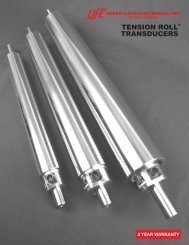
SECTION 1PRODUCT DESCRIPTION1.1 GENERAL DESCRIPTIONThe Model "<strong>TR</strong>" Tension Roll® Transducer is an electro-mechanical device that converts web tensioninto a D.C. voltage which is proportional to tension. The voltage is amplified in external electroniccircuitry and displayed on an analog or digital meter which is calibrated to indicate actual web tension,expressed in pounds, ounces, grams, kilograms, newtons or any other desirable units. The output voltagemay also be supplied to a regulator circuit to control tension automatically.The <strong>TR</strong> transducer is unique because it combines a dead-shaft idler roll with tension sensors built intoeach end of the roll.The information in this Section will help give a clear understanding of the Model "<strong>TR</strong>" Transducer, how itworks and how it is used.1.2 CONS<strong>TR</strong>UCTION AND MECHANICAL OPERATION (see figure 1)In a typical installation, the transducer is mounted in the same way as any dead-shaft idler roll. No specialprovisions need be made. The transducer shaft is available with plain ends for mounting in shaft hangers,drilled and tapped ends for mounting by thru-frame bolts, or milled flats with a bolt hole thru formounting on the edge of machine frames. See Figure 5.The roll is manufactured to industry standards for Total Indicated Runout (TIR), surface finish and taper.Every roll is dynamically balanced to specifications more stringent than the typical idler roll.The stainless steel shaft inside the roll is much larger in diameter than the ends for increased stiffness.Figure 1 - CUT-AWAY VIEW OF MODEL <strong>TR</strong> <strong>TR</strong>ANSDUCERThe bearings are self-aligning ball type with a seal on the side toward the center of the roll to preventgrease from entering the roll. An external flush-type grease fitting is provided for each bearing for relubrication.A shield on the other side of the bearing retains the grease without introducing any additionaldrag. A retaining ring at the bearing on the end of the transducer opposite the electrical connector keepsthe roll in place while a sliding sleeve on the other end allows the roll to expand in length with risingtemperature without causing any stress on the roll or bearings.Inside the transducer are two dual cantilever beams, one at each end of the roll, with strain gages mountedon the top and bottom surfaces of each. The bearings are attached to the free end of each beam. When webtension is applied the beam deflects a small amount, causing an electrical output from the strain gages.1


