TR Instruction Manual - Dover Flexo Electronics, Inc
TR Instruction Manual - Dover Flexo Electronics, Inc
TR Instruction Manual - Dover Flexo Electronics, Inc
You also want an ePaper? Increase the reach of your titles
YUMPU automatically turns print PDFs into web optimized ePapers that Google loves.
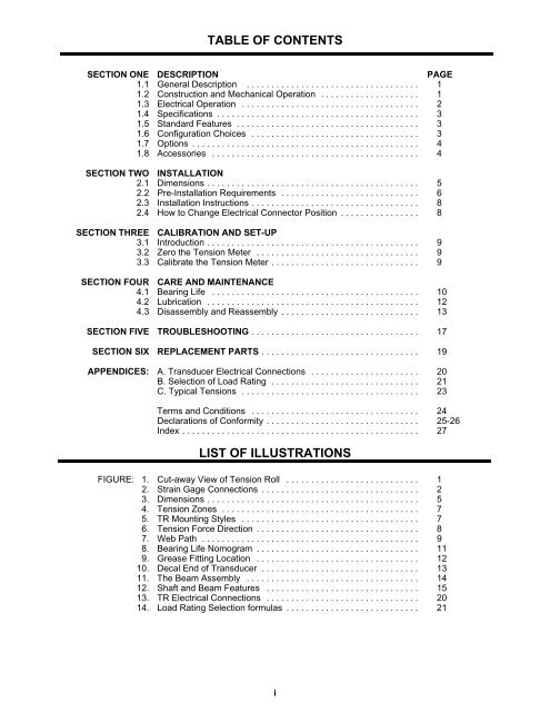
TABLE OF CONTENTSSECTION ONE DESCRIPTION PAGE1.1 General Description ................................... 11.2 Construction and Mechanical Operation .................... 11.3 Electrical Operation .................................... 21.4 Specifications ......................................... 31.5 Standard Features ..................................... 31.6 Configuration Choices .................................. 31.7 Options .............................................. 41.8 Accessories .......................................... 4SECTION TWO INSTALLATION2.1 Dimensions........................................... 52.2 Pre-Installation Requirements ............................ 62.3 Installation <strong>Instruction</strong>s.................................. 82.4 How to Change Electrical Connector Position ................ 8SECTION THREE CALIBRATION AND SET-UP3.1 Introduction ........................................... 93.2 Zero the Tension Meter ................................. 93.3 Calibrate the Tension Meter.............................. 9SECTION FOUR CARE AND MAINTENANCE4.1 Bearing Life .......................................... 104.2 Lubrication ........................................... 124.3 Disassembly and Reassembly ............................ 13SECTION FIVE <strong>TR</strong>OUBLESHOOTING .................................. 17SECTION SIX REPLACEMENT PARTS ................................ 19APPENDICES: A. Transducer Electrical Connections ...................... 20B. Selection of Load Rating .............................. 21C. Typical Tensions .................................... 23Terms and Conditions .................................. 24Declarations of Conformity............................... 25-26Index ................................................ 27LIST OF ILLUS<strong>TR</strong>ATIONSFIGURE: 1. Cut-away View of Tension Roll ........................... 12. Strain Gage Connections ................................ 23. Dimensions........................................... 54. Tension Zones ........................................ 75. <strong>TR</strong> Mounting Styles .................................... 76. Tension Force Direction ................................. 87. Web Path ............................................ 98. Bearing Life Nomogram ................................. 119. Grease Fitting Location ................................. 1210. Decal End of Transducer ................................ 1311. The Beam Assembly ................................... 1412. Shaft and Beam Features ............................... 1513. <strong>TR</strong> Electrical Connections ............................... 2014. Load Rating Selection formulas ........................... 21i


