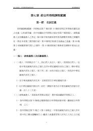
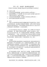
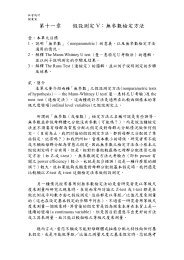
ÄÄÄÄIn Proceedings of 1995 IEEE Int’l Conf. on Robotics and Automationf maxfinitial configuration1xaggressivezoneconservative zonex s x m#collisionÄÄÄÄobstacleConstraint Volume created bylinking the spheres <strong>with</strong> cones.The union of the spheresand the cones is theconstraint volume.f min0ÄÄÄÄfinal configurationFigure 3. Search resolution refinement model: collisionratio dependent step size. Note x m = 728 for6 dof.which is shown in Figure 3. This model grows the step sizeinitially if, at a given configuration q, there were only a fewcollisions before a feasible q’ is found. We call this region off the aggressive zone. Once there are more than a fixed numberof collisions x s detected at q, f becomes smaller than 1,which effectively makes s i+1 smaller than s i. An important parameteris x s . It is essentially the number of collisions one assumesunder normal circumstances the planner expects beforemaking a successful move. If the number of collisions encounteredbefore making a successful move is near this value,the search resolution will stay very close to the previouslyused resolution. However, if significantly more collisions areencountered, the resolution value drops quickly, down to thefloor value set by the user, in the conservative zone. If relativelyfew collisions are encountered before making a successfulmove, the next search resolution may grow by a factordetermined by the curve between x=0 and x=x s . Since we donot know the distribution of the C–space shapes and clutteredness,x s can only be determined through empirical means. Bymoving this cutoff threshold between the two zones, one canchange the behavior of the refinement model so as to effect amore aggressive or more conservative policy. Notice that themaximum step size factor f max and the minimum step size factorf min are the other parameters in the model. With these parameters,we set also a ceiling and a floor for s i+1 so that theuser may enforce control over the search resolution. Forinstance, the maximum step size should not exceed the minimumobstacle dimension so that the moving object would notjump through an obstacle from one configuration to the next.These parameters are case dependent. In our experiments, wehave used f min = 1 / f max and f max = 2.3.2 Biased PathsThere are various ways to achieve bias in searching for a path.An obvious way is to block all undesirable passages by artifi-ÄÄFigure 4. Constraint Volume specified by placing a set ofcircles (spheres for 3d) of various sizes.cial obstacles. However, in 3D environments, it may not beintuitive for the user to specify such obstacles. The user needsto know the locations and dimensions of these passages in orderto place artificial obstacles <strong>with</strong> reasonable sizes. Thisprocess may be tedious when the number of these passages arelarge. In addition, it is difficult to verify that these artificialobstacles will not prevent the planner from finding an otherwisefeasible path, e.g., a path that requires the use of parts ofan undesirable passage to adjust the orientation of the object.In our system, we developed a different approach in which theuser specifies a constraint volume by placing a set of spheresof various diameters (user specified) at critical branchingpoints in the workspace where the user wants to prefer onedirection to the others. These spheres are then linked together<strong>with</strong> cones smoothly to form a volume. The exterior of thevolume is treated differently than obstacles. While the originalobstacles are still there, confining the motion of an LRU,this volume places an additional constraint on the motion ofthe LRU. More specifically, a certain set of points (calledconstraint points) is constrained to stay inside the volume,while the rest of the concerned LRU may leave the volume to,for instance, make orientational adjustments. Theseconstraint points may be critical surface landmarks of anLRU, its centroid, or some other references. Note that a givenconstraint through a set of user–specified spheres does notconstitute a single initial path. It merely signifies that the selectedconstraint points will trace out a path, during the search,that lies inside the corresponding constraint volume. In fact incases where fewer than three (non–colinear) constraint pointsare used, indeed at some configurations the LRU may be incollision <strong>with</strong> obstacles. Furthermore, such a constraint volumeis allowed to overlap <strong>with</strong> obstacles, thus making itsselection much less demanding of the user. Figure 4 illustratessuch a constraint volume for the case shown in Figure 2 to biasthe search to find path (b). The algorithm used in the RPP to
In Proceedings of 1995 IEEE Int’l Conf. on Robotics and Automationbuild heuristic potential fields is modified to account for thisconstraint volume. The potential values inside the constraintvolume are lower than those outside such that during thesearch process configurations that are inside or closer to thevolume are preferred to those that are outside or farther. Thiseffect is achieved by generating potential field in two phases:inside the constraint volume followed by outside the volume.This constraining mechanism is empirical but it provides aneasy and flexible way for the user to specify a bias in the pathsearching process. It can also be used when the user observesor predicts that the heuristic potential fields used in the RPPcan not provide an effective guidance for the search.4 Results and DiscussionWe have applied the system to several maintainability studyproblems. Figure 5 presents a case where the accessibility ofan irregularly shaped LRU (Figure 5(a)) inside an assembly.Figures 5(b) through 5(f) show a series of snapshots taken asthe LRU moves along the computed path. The difficulty ofthis case lies in the fact that the LRU is so irregularly shaped.Any approximation using bounding box or spheres would notbe efficient. Also, given the shape, the computation of a C–space representation from the environment is impractical.The path took several hours of computation time on an SGIRealityEngine computer (see the last section for more detailson software as well as hardware used).Figure 6 includes a retrospective study where a set of previouslystudied design were made available to us. In the design,the LRU is surrounded by several pipes as shown in Figure6(a). The manual approach the designers used previouslyhad determined that some of the pipes were in the way. Thosepipes were consequently redesigned. To illustrate the difference,we show both sets of pipes in the figure (see pipes thatsplit and then join – one of the branches belongs to the old design;where they fuse together is the part that did not getchanged in the new design). We applied our automated systemon both the old design, and the new one. First, we confirmedthat a path found using the new design has collisionconfigurations <strong>with</strong> the old design. Hence, those changeswere necessary. For instance, Figures 6(c) and 6(d) show twocollision situations where the LRU was in collision <strong>with</strong> thepipes from the old design, while clearing the new pipes. However,we have also found, that some of the redesign were indeedunnecessary. For example, the section of pipe near thetop left hand corner of Figure 6(d) (right below the letter d) didnot pose any collision threats to the LRU along the path found.Through this particular study, we show that not only is the automatedsystem faster relative to the manual approach, it is amore accurate tool as well. Previously, when the designer isin doubt, he would tend to be more conservative in his designin order to leave room for error. Now, <strong>with</strong> the automated system,he will be provided <strong>with</strong> accurate information as to whereexactly changes should be made.To study the effectiveness of the adaptive multi–resolutionsearch mechanism, we applied the system to some customizedmanufacturing cases, where specially designed parts aretested for manufacturability. In Figure 7, we show resultsfrom one such case, where a set of closely fitted matting partsis designed to be installed together. Specifically, an insert partis designed to be inserted into a twisted cavity <strong>with</strong>out deformation(see Figure 7(a)). The design allowed only 10 millclearance between them. Since both the insert and the cavityare twisted in two dimensions, it is not intuitive to know, giventhe curvature, that the insert can be either installed inside thecavity or taken out. With our automated system, we started<strong>with</strong> a 5 mill search resolution, <strong>with</strong> which the system wasable to move the insert out 1/4 of the length after a few hoursof computation. Then, as more and more collisions are detectedfor each move, the search resolution was reduced automaticallyaccording to the model presented in the last section.Eventually, at 1 mill search resolution, the insert came out 1/3of the length and was determined to be totally stuck (see Figure7(b)). The design was thus turned down and a rework wasordered. Note the perspective effect of the display in Figure7. The cross section of the parts at both ends are of the samedimension. So the reason for it to get stuck is the effect of thetwisting in the middle part.We used several cases to study the constraint volume approach.Figure 8 shows a case where the LRU is located in acluttered environment under a set of pipes (see Figures 8(a)and 8(e)). There is an opening between the pipes that is wideenough for the object to get out when its orientation is alignedcorrectly. The LRU in its initial configuration is orthogonalto this opening (as shown in Figure 8(e)), and the study is basicallyto show whether there is enough room for the object tomake such an orientation change to get out through such a designedopening. Our study shows that the initial configurationfavors a path (Figures 8(h) through 8(j)) that does not use theopening. Figures 8(k) and 8(l) show close up views of twoconfigurations along the path. In order to force the LRU tocome out through the designed opening, we specified twospheres: one at the initial configuration and one right on theother side of the obstacle pipes, forming a constraint volumethat cuts off the undesirable path. Figures 8(b) through 8(d)show the path found after applying this constraint volume.Figures 8(f) and 8(g) provide a close up view of two configurationsalong that path.Overall, the cases presented here are difficult ones for traditional,CAD–based move–and–detect–collision type ofmanual maintainability systems. We have realized, by usingthe automated system presented here, a tremendous productivitygain. In the past <strong>with</strong> the manual approach a studywould take several days of tedious work. Now, typically, it