Assembly Maintainability Study with Motion Planning
Assembly Maintainability Study with Motion Planning
Assembly Maintainability Study with Motion Planning

You also want an ePaper? Increase the reach of your titles
YUMPU automatically turns print PDFs into web optimized ePapers that Google loves.
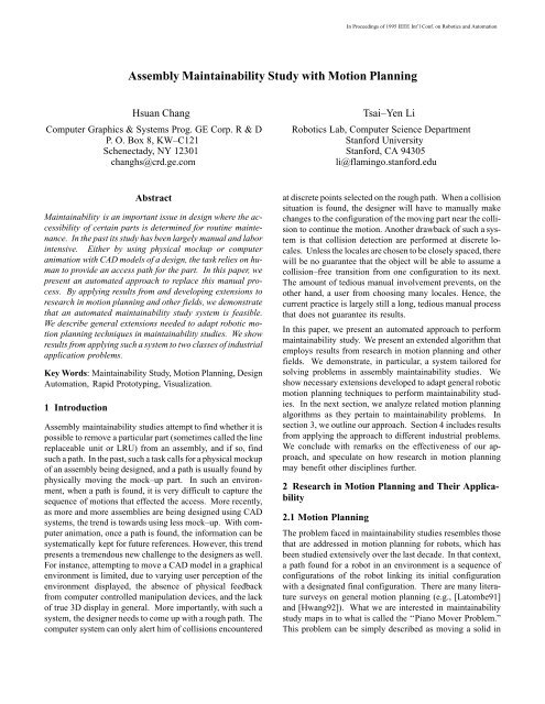
In Proceedings of 1995 IEEE Int’l Conf. on Robotics and Automation(b)initial configurationÄÄÄÄÄÄÄÄÄÄÄÄÄÄÄÄÄÄÄÄÄobstaclepath (a)final configurationFigure 2. Typical potential guided planner will find (a) before(b), because (a) is shorter.Secondly, sometimes there are preferred neighborhoodsthrough which an access path should be found. This is particularlytrue <strong>with</strong> maintainability studies, where access is oftenlimited by realistic concerns of an assembly such as the sizeof a moving object, support regions for tools, heat sources toavoid, or simply access convenience. For instance, Figure 2illustrates a case where, using potential field guided plannerssuch as RPP, path (a) would be found because it is a shorterpath and the moving object has more room to maneuver.Instead, path (b) as shown may be preferred from maintainabilitypoint of view because of access support and ease ofreach. An obvious solution to input such bias is to place additionalobstacles in the free space to judiciously block certainpassages. But such solution requires the user to anticipate undesirablepaths before hand. For complicated 3D assemblies,it may be hard to complete such anticipation.The third aspect is the complexity of objects and the relatedcost in detecting collision. To effect compliant motion (wherethe moving object is in contact <strong>with</strong> the obstacles as it moves),exact collision check is required. In robotics, such polygonal–based collision detection can often be avoided by using simplifiedmodels. In design automation, a sophisticated partusually replaces a subassembly of smaller parts in the old design.One consequence of such increased complexity in shapeis that more polygons are needed to describe its shape, resultingin more time consuming polygonal collision checks.Another difference lies in the accuracy of collision detection.In ordinary robotic applications, it is acceptable to useapproximate (and conservative) collision detection becauseof control uncertainty and safety concerns. In maintainabilitystudy, the need to confine to tolerances and accuracy in themodels capturing the environment demands accurate collisiondetection.3 An Automated <strong>Maintainability</strong> <strong>Study</strong> SystemBy incorporating solutions to the above concern, we developedan automated maintainability system. Its planner isbased on the RPP. For collision detection, we implementedthe algorithm reported in [Quinlan94] to reduce the numberof calls to an exact collision checking routine that models after[Gilbert85]. We review relevant details of the RPP first (Detailscan be found in [Barraquand90]). Then, we elaborate onour extension to the planner to handle some of the requirementsdescribed in the previous section.The RPP uses heuristic potential fields as a guide to search fora path and uses Brownian motions (random walks) to escapelocal minima of the potential fields. The heuristic potentialfields are goal oriented fields created in the workspace forpoints selected from the robot. Each of these potential fieldshas unique global minimum at the goal configuration of therobot. A potential function P is defined over these potentialfields such that P(q) = 0 iff q = q t , where q is any configuration,and q t is the goal configuration. Let C(q) be a collision checkingfunction that returns ok when q is collision–free. The robotfollows the gradient of P from q to its neighbor configurationq’ if and only if P(q’) < P(q), C(q’) = ok, and q q t . Thedistance between q and q’ is the search resolution. When thesearch reaches a local minimum in terms of function P, a presetnumber of random walks, each of which is followed by agradient motion, are performed to escape the local minimum.When all these attempts fail, a backtrack step is performed toretract part of the path found so far.3.1 Dynamic, Adaptive Refinement of Search ResolutionA heuristic approach was developed to change the search resolutionadaptively depending on how cluttered the environmentis. Although we do not explicitly compute the C–spaceand do not know how the C–obstacle surfaces are shaped anddistributed, we use the number of collisions encountered atconfiguration q as an indicator to how tight the C–obstaclesurfaces are in the vicinity of q. Specifically, assuming x isthe number of collisions encountered so far at configurationq. The heuristic model used for this adaptive multi–resolutionsearch is given bys i+1 = s i * fwhere s i+1 is the current step size, s i is the successful resolutionused in the last move, and . xf = f max – 0 < x < x sx sf min +12 x m – xx m – x sx s < x
ÄÄÄÄIn Proceedings of 1995 IEEE Int’l Conf. on Robotics and Automationf maxfinitial configuration1xaggressivezoneconservative zonex s x m#collisionÄÄÄÄobstacleConstraint Volume created bylinking the spheres <strong>with</strong> cones.The union of the spheresand the cones is theconstraint volume.f min0ÄÄÄÄfinal configurationFigure 3. Search resolution refinement model: collisionratio dependent step size. Note x m = 728 for6 dof.which is shown in Figure 3. This model grows the step sizeinitially if, at a given configuration q, there were only a fewcollisions before a feasible q’ is found. We call this region off the aggressive zone. Once there are more than a fixed numberof collisions x s detected at q, f becomes smaller than 1,which effectively makes s i+1 smaller than s i. An important parameteris x s . It is essentially the number of collisions one assumesunder normal circumstances the planner expects beforemaking a successful move. If the number of collisions encounteredbefore making a successful move is near this value,the search resolution will stay very close to the previouslyused resolution. However, if significantly more collisions areencountered, the resolution value drops quickly, down to thefloor value set by the user, in the conservative zone. If relativelyfew collisions are encountered before making a successfulmove, the next search resolution may grow by a factordetermined by the curve between x=0 and x=x s . Since we donot know the distribution of the C–space shapes and clutteredness,x s can only be determined through empirical means. Bymoving this cutoff threshold between the two zones, one canchange the behavior of the refinement model so as to effect amore aggressive or more conservative policy. Notice that themaximum step size factor f max and the minimum step size factorf min are the other parameters in the model. With these parameters,we set also a ceiling and a floor for s i+1 so that theuser may enforce control over the search resolution. Forinstance, the maximum step size should not exceed the minimumobstacle dimension so that the moving object would notjump through an obstacle from one configuration to the next.These parameters are case dependent. In our experiments, wehave used f min = 1 / f max and f max = 2.3.2 Biased PathsThere are various ways to achieve bias in searching for a path.An obvious way is to block all undesirable passages by artifi-ÄÄFigure 4. Constraint Volume specified by placing a set ofcircles (spheres for 3d) of various sizes.cial obstacles. However, in 3D environments, it may not beintuitive for the user to specify such obstacles. The user needsto know the locations and dimensions of these passages in orderto place artificial obstacles <strong>with</strong> reasonable sizes. Thisprocess may be tedious when the number of these passages arelarge. In addition, it is difficult to verify that these artificialobstacles will not prevent the planner from finding an otherwisefeasible path, e.g., a path that requires the use of parts ofan undesirable passage to adjust the orientation of the object.In our system, we developed a different approach in which theuser specifies a constraint volume by placing a set of spheresof various diameters (user specified) at critical branchingpoints in the workspace where the user wants to prefer onedirection to the others. These spheres are then linked together<strong>with</strong> cones smoothly to form a volume. The exterior of thevolume is treated differently than obstacles. While the originalobstacles are still there, confining the motion of an LRU,this volume places an additional constraint on the motion ofthe LRU. More specifically, a certain set of points (calledconstraint points) is constrained to stay inside the volume,while the rest of the concerned LRU may leave the volume to,for instance, make orientational adjustments. Theseconstraint points may be critical surface landmarks of anLRU, its centroid, or some other references. Note that a givenconstraint through a set of user–specified spheres does notconstitute a single initial path. It merely signifies that the selectedconstraint points will trace out a path, during the search,that lies inside the corresponding constraint volume. In fact incases where fewer than three (non–colinear) constraint pointsare used, indeed at some configurations the LRU may be incollision <strong>with</strong> obstacles. Furthermore, such a constraint volumeis allowed to overlap <strong>with</strong> obstacles, thus making itsselection much less demanding of the user. Figure 4 illustratessuch a constraint volume for the case shown in Figure 2 to biasthe search to find path (b). The algorithm used in the RPP to
In Proceedings of 1995 IEEE Int’l Conf. on Robotics and Automationbuild heuristic potential fields is modified to account for thisconstraint volume. The potential values inside the constraintvolume are lower than those outside such that during thesearch process configurations that are inside or closer to thevolume are preferred to those that are outside or farther. Thiseffect is achieved by generating potential field in two phases:inside the constraint volume followed by outside the volume.This constraining mechanism is empirical but it provides aneasy and flexible way for the user to specify a bias in the pathsearching process. It can also be used when the user observesor predicts that the heuristic potential fields used in the RPPcan not provide an effective guidance for the search.4 Results and DiscussionWe have applied the system to several maintainability studyproblems. Figure 5 presents a case where the accessibility ofan irregularly shaped LRU (Figure 5(a)) inside an assembly.Figures 5(b) through 5(f) show a series of snapshots taken asthe LRU moves along the computed path. The difficulty ofthis case lies in the fact that the LRU is so irregularly shaped.Any approximation using bounding box or spheres would notbe efficient. Also, given the shape, the computation of a C–space representation from the environment is impractical.The path took several hours of computation time on an SGIRealityEngine computer (see the last section for more detailson software as well as hardware used).Figure 6 includes a retrospective study where a set of previouslystudied design were made available to us. In the design,the LRU is surrounded by several pipes as shown in Figure6(a). The manual approach the designers used previouslyhad determined that some of the pipes were in the way. Thosepipes were consequently redesigned. To illustrate the difference,we show both sets of pipes in the figure (see pipes thatsplit and then join – one of the branches belongs to the old design;where they fuse together is the part that did not getchanged in the new design). We applied our automated systemon both the old design, and the new one. First, we confirmedthat a path found using the new design has collisionconfigurations <strong>with</strong> the old design. Hence, those changeswere necessary. For instance, Figures 6(c) and 6(d) show twocollision situations where the LRU was in collision <strong>with</strong> thepipes from the old design, while clearing the new pipes. However,we have also found, that some of the redesign were indeedunnecessary. For example, the section of pipe near thetop left hand corner of Figure 6(d) (right below the letter d) didnot pose any collision threats to the LRU along the path found.Through this particular study, we show that not only is the automatedsystem faster relative to the manual approach, it is amore accurate tool as well. Previously, when the designer isin doubt, he would tend to be more conservative in his designin order to leave room for error. Now, <strong>with</strong> the automated system,he will be provided <strong>with</strong> accurate information as to whereexactly changes should be made.To study the effectiveness of the adaptive multi–resolutionsearch mechanism, we applied the system to some customizedmanufacturing cases, where specially designed parts aretested for manufacturability. In Figure 7, we show resultsfrom one such case, where a set of closely fitted matting partsis designed to be installed together. Specifically, an insert partis designed to be inserted into a twisted cavity <strong>with</strong>out deformation(see Figure 7(a)). The design allowed only 10 millclearance between them. Since both the insert and the cavityare twisted in two dimensions, it is not intuitive to know, giventhe curvature, that the insert can be either installed inside thecavity or taken out. With our automated system, we started<strong>with</strong> a 5 mill search resolution, <strong>with</strong> which the system wasable to move the insert out 1/4 of the length after a few hoursof computation. Then, as more and more collisions are detectedfor each move, the search resolution was reduced automaticallyaccording to the model presented in the last section.Eventually, at 1 mill search resolution, the insert came out 1/3of the length and was determined to be totally stuck (see Figure7(b)). The design was thus turned down and a rework wasordered. Note the perspective effect of the display in Figure7. The cross section of the parts at both ends are of the samedimension. So the reason for it to get stuck is the effect of thetwisting in the middle part.We used several cases to study the constraint volume approach.Figure 8 shows a case where the LRU is located in acluttered environment under a set of pipes (see Figures 8(a)and 8(e)). There is an opening between the pipes that is wideenough for the object to get out when its orientation is alignedcorrectly. The LRU in its initial configuration is orthogonalto this opening (as shown in Figure 8(e)), and the study is basicallyto show whether there is enough room for the object tomake such an orientation change to get out through such a designedopening. Our study shows that the initial configurationfavors a path (Figures 8(h) through 8(j)) that does not use theopening. Figures 8(k) and 8(l) show close up views of twoconfigurations along the path. In order to force the LRU tocome out through the designed opening, we specified twospheres: one at the initial configuration and one right on theother side of the obstacle pipes, forming a constraint volumethat cuts off the undesirable path. Figures 8(b) through 8(d)show the path found after applying this constraint volume.Figures 8(f) and 8(g) provide a close up view of two configurationsalong that path.Overall, the cases presented here are difficult ones for traditional,CAD–based move–and–detect–collision type ofmanual maintainability systems. We have realized, by usingthe automated system presented here, a tremendous productivitygain. In the past <strong>with</strong> the manual approach a studywould take several days of tedious work. Now, typically, it
In Proceedings of 1995 IEEE Int’l Conf. on Robotics and Automationtakes a few minutes to several hours to generate a path if it canfind one. With the automated system available, designers canalso perform several studies simultaneously. Depending onhow complex the study is, the productivity gain ranges fromseveral factors to an order of magnitude.But this system is not <strong>with</strong>out problems. In general, we realizethat most of the time is still spent on collision checking. Incertain cases (that are not included in this paper) we experiencedpronounced effect from the probabilistic nature of theplanner. Some of our studies are non–conclusive after severaldays (one particular assembly took more than a week (on theSGI workstation mentioned above) and was eventually terminatedmanually). To address this problem, we are planning onexploring other techniques such as the randomized roadmapalgorithm in [Kavraki94]. In that direction, we will try to emphasizethe deterministic behavior of a planner.5 ConclusionsWe developed a first–known practical automated assemblymaintainability study system by incorporating results from researchin robotics motion planning. In this paper, we presenta dynamic, adaptive multi–resolution model in the system.This search resolution adaptation model overcomes the difficultiesfixed resolution motion planners experience. In addition,a bias mechanism was developed to facilitate specificationof access path preference that is required in typicalmaintainability and manufacturability studies. A number ofindustrial application studies are presented in the paper thatuse the system to show that the automated system not onlysolves otherwise–difficult problems but also lends significantproductivity improvement over existing computer–assistedmanual approach. We also show that such a system is an effectivetool for custom manufacturing where manufacturabilitycan be tested before parts are made. With the results, we areconfident that this automated maintainability system points toa new direction of applications of research in robotic motionplanning. We hope that it will serve to provide additionaldriving force for research in motion planning in general.AcknowledgementsThe automated system is encapsulated in ProductVision, acommercial software developed at GE Corporate R&D to producethe results shown in this paper. Briefly, ProductVisionprovides a visual environment on UNIX workstations to importgeometrical models (from major CAD packages) to generateaccess paths to test assembly feasibility using the motionplanner described in this paper. It also creates a swept surfaceto outline the physical space required of a given path for thegiven LRU. Results can be presented using computer animationin the software as shown in the accompanying Video Proceedings.The reported applications have been performed onSGI’s RealityEngine, <strong>with</strong> two R4400 processors at 150 MHZand 128 MBytes of main memory.References[Barraquand90] Barraquand, J. and Latombe, J.–C. ‘‘AMonte–Carlo Algorithm for Path <strong>Planning</strong> <strong>with</strong> Many Degreesof Freedom,’’ Proc. IEEE Int’l Conf. on Robotics andAutomation, 1712–1717 (1990).[Donald87] Donald, B. ‘‘A Search Algorithm for <strong>Motion</strong><strong>Planning</strong> <strong>with</strong> Six Degrees of Freedom,’’ Artificial Intelligence,31. 295–353 (1987).[Gilbert85] Gilbert E.G. and Johnson D. W. ‘‘Distance Functionsand Their Application to Robot Path <strong>Planning</strong> in thePresence of Obstacles,’’ IEEE Trans. on Robotics and Automation,RA–1. 21–30 (1985).[Hwang92] Hwang, Y. K. Ahuja, N. ‘‘Gross <strong>Motion</strong> <strong>Planning</strong>– A Survey,’’ ACM Computing Surveys, 24. 220–291 (1992).[Kavraki94] Kavraki, L. Latombe, J.–C. ‘‘Randomized Preprocessingof Configuration Space for Fast Path <strong>Planning</strong>,’’Proc. IEEE Int’l Conf. on Robotics and Automation, preprint.(1994).[Latombe91] Latombe, J.–C. Robot <strong>Motion</strong> <strong>Planning</strong>, KluwerAcademic Publishers, Boston, 1991.[Lozano79] Lozano–Perez, T. and Wesley, M., ‘‘An Algorithmfor <strong>Planning</strong> Collision–free Paths Among PolyhedralObstacles,’’ Comm. of ACM, 22. 560–570 (1979).[Lozano83] Lozano–Perez, T. ‘‘Spatial <strong>Planning</strong>: A ConfigurationSpace Approach,’’ IEEE Trans. on Computers, C–32.108–120 (1983).[Lozano91] Lozano–Perez, T and O’Donnel, P. ‘‘Parallel Robot<strong>Motion</strong> <strong>Planning</strong>,” Proc. IEEE Int’l Conf. on Robotics andAutomation, 1000–1007, 1991.[Lozano93] Lozano–Perez, T and Wilson, R. ‘‘<strong>Assembly</strong> Sequencingfor Arbitrary <strong>Motion</strong>s,” Proc. IEEE Int’l Conf. onRobotics and Automation, 1993.[Quinlan94] Quinlan, S. ‘‘Efficient Distance Computation betweenNon–convex Ojbects,” Proc. IEEE Int’l Conf. on Roboticsand Automation, 1994.[Schwartz83b] Schwartz, J. T. and Sharir, M., ‘‘On the PianoMovers’ Problem: II. Advances in Applied Mathematics, 4.298–351 (1983).[Wilson92a] Wilson, R. and Latombe, J.–C. ‘‘On the QualitativeStructure of a Mechanical <strong>Assembly</strong>,” Proc. IEEE Int’lConf. on Robotics and Automation, 1992.[Wilson92b] Wilson, R. and Matsui, T. ‘‘Partitioning an <strong>Assembly</strong>for Infinitesimal <strong>Motion</strong>s in Translation and Rotation,”Proc. IEEE Int’l Conf. on Intelligent Robotics and Systems,1992.