Hydraulic Quick Couplings - Parker
Hydraulic Quick Couplings - Parker
Hydraulic Quick Couplings - Parker

You also want an ePaper? Increase the reach of your titles
YUMPU automatically turns print PDFs into web optimized ePapers that Google loves.
<strong>Hydraulic</strong><strong>Quick</strong><strong>Couplings</strong>B-1maku GmbH & Co. KG · 73630 Remshalden · Telefon (0 71 51) 7 26 26 · Telefax (0 71 51) 7 42 01 · www.maku-industrie.de
<strong>Hydraulic</strong> <strong>Quick</strong> <strong>Couplings</strong>IntroductionDouble Shut-Off and Straight-Thru <strong>Couplings</strong>B <strong>Hydraulic</strong>s<strong>Parker</strong> hydraulic couplings have a wide variety of designs,each tailored to a particular application or use. This catalog isarranged according to those categories. In each section theconstruction of a specific design will be detailed. However,based on the valving of the coupling, hydraulic couplingsgenerally fall into one of two groups, either Double Shut-Offor Straight-Thru.Double Shut-Off couplings are used extensively when it isimportant to minimize fluid loss upon disconnection. Bothhalves of the coupler, the body and the nipple, contain shutoffvalves. These valves open automatically when the bodyand nipple are connected, and close automatically when thetwo halves are disconnected—keeping fluid loss to aminimum.<strong>Parker</strong> Straight-Thru couplings have no valves in either halfand are ideal for maximum flow application. Their smooth,open bore offers the lowest pressure drop of any quickdisconnect coupling, and allows them to be thoroughlycleaned. Since there are no valves in either half, fluid flowshould be shut off before the coupling is disconnected.Rated PressureRated pressure for the <strong>Parker</strong> hydraulic couplings range from30 to 15,000 psi, depending on the coupling series, size andmaterials. Rated pressures as shown in this catalog aredefined by ISO 5598, as “the qualified operating pressureswhich are recommended for a component or a system by themanufacturer.” <strong>Parker</strong> “Rated Pressures” have beenestablished on the basis of laboratory tests which include, butare not limited to, static burst tests and multiple cycle impulsetests. System characteristics such as high cycling rates andhigh amplitude shocks either hydraulic or mechanical, canreduce the functioning life of a coupling,even if the system’s nominal pressure falls within the ratedpressure range of the coupling.For assistance in analyzing your application, contact yournearest <strong>Parker</strong> sales office or the <strong>Quick</strong> Coupling Divisionin Minneapolis.Refer to the Safety Guide at the end of this catalog forconsiderations when selecting a <strong>Quick</strong> Coupling.Refer to the Fluid Compatibility Chart (note Table of Contents)for seal selection assistance for both Double Shut-Off andStraight-Thru couplings.Checklist for Selecting <strong>Quick</strong> <strong>Couplings</strong>q What are the functional requirements of the coupling?q What is the maximum working pressure of the application?q Which seals and body material are compatible with thesystem’s fluid?q Is the application static or dynamic?q What size coupler is required?q What is the maximum pressure drop suitable forthe application?q Does the application require the ability to connectand disconnect under pressure?q What is the media temperature and ambient temperature?q What end configurations are required?q Is an industry interchange coupler required?q Is air inclusion and fluid loss a concern in the application?B-2maku GmbH & Co. KG · 73630 Remshalden · Telefon (0 71 51) 7 26 26 · Telefax (0 71 51) 7 42 01 · www.maku-industrie.de
<strong>Hydraulic</strong> <strong>Quick</strong> <strong>Couplings</strong>Table of ContentsIntroduction .............................................................B-2Coupling Selection Guide......................................B-4General Purpose <strong>Couplings</strong>60 Series.............................................................B-5–8Couplers............................................................B-7–8Nipples ..............................................................B-7–8Repair Kits & Replacement Parts ...........................B-860 Series Steam .....................................................B-9Couplers................................................................B-9Nipples ..................................................................B-96600 Series.....................................................B-10–11Couplers..............................................................B-11Nipples ................................................................B-11SM Series .......................................................B-12–13Couplers..............................................................B-13Nipples ................................................................B-13HP Series........................................................B-14–15Couplers..............................................................B-15Nipples ................................................................B-154000 Series.....................................................B-16–17Couplers..............................................................B-17Nipples ................................................................B-174200 Series......................................................B-18-19Couplers..............................................................B-19Nipples ................................................................B-19Non-Spill <strong>Couplings</strong>NS Series.........................................................B-20-21Couplers..............................................................B-21Nipples ................................................................B-21Adapters................................................................B-22FF Series .........................................................B-23-24Couplers..............................................................B-24Nipples ................................................................B-24FEM Series ......................................................B-25-26Couplers..............................................................B-26Nipples ................................................................B-26FC Series ..............................................................B-27Nipples ................................................................B-27FEC Series............................................................B-28Nipples ................................................................B-28FH Series.........................................................B-29-30Couplers..............................................................B-30Nipples ................................................................B-30FS Series .........................................................B-31-32Couplers..............................................................B-32Nipples ................................................................B-32Repair Kits...........................................................B-32Connect Under Pressure <strong>Couplings</strong>6100 Series......................................................B-33-35Couplers.........................................................B-34-35Nipples...........................................................B-34-358200 Series......................................................B-36-37Couplers..............................................................B-37Nipples ................................................................B-379200 Series......................................................B-38-39Couplers..............................................................B-39Nipples ................................................................B-395000 Series......................................................B-40-41Couplers..............................................................B-41Nipples ................................................................B-41High Pressure <strong>Couplings</strong>3000 Series......................................................B-42-43Couplers..............................................................B-43Nipples ................................................................B-43TC Series ..............................................................B-44Couplers..............................................................B-44Nipples ................................................................B-441141 Series...........................................................B-45Mold Coolant Line <strong>Couplings</strong>Moldmate Series..............................................B-46-50Couplers.........................................................B-47-48Sub Assemblies & Replacement Parts...............B-48Nipples...........................................................B-49-50High Flow <strong>Couplings</strong>ST Series .........................................................B-51-53Couplers..............................................................B-52Nipples ................................................................B-53Water Service........................................................B-54HO Series..............................................................B-55Special Purpose - MiniatureDM Series.......................................................B56-B57Dust Plugs and Dust Caps ............................B-58-60Ordering Information ...........................................B-61Promotional Products-Keychains .......................B-62B <strong>Hydraulic</strong>sB-3maku GmbH & Co. KG · 73630 Remshalden · Telefon (0 71 51) 7 26 26 · Telefax (0 71 51) 7 42 01 · www.maku-industrie.de
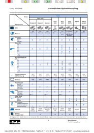
<strong>Hydraulic</strong> <strong>Quick</strong> <strong>Couplings</strong>Coupling Selection & Ordering GuideB <strong>Hydraulic</strong>sValving Body Material* Locking Std. Seal Temp RatedSize Br S S3 S6 Mechanism Material** Range** PressureGeneral Purpose60 Series Poppet 1/8 - 2 1/2" l l l l Ball Nitrile -40° to +250° F 1000 to 5000 PSI60 Series Steam Poppet 1/4 to 1" l Ball Ethylene Propylene -65° to +400° F6600 Series Poppet 1/4 to 1" l Ball Nitrile -40° to +250° F 4000 to 5000 PSISM Series Poppet 1/4 to 3/4" l Ball Nitrile -40° to +250° F 4500 to 6000 PSIHP Series Poppet 1 to 1 1/2" l Ball Nitrile -40° to +250° F 5000 PSI4000 Series Poppet/Ball 1/4 to 1" l Ball Nitrile -40° to +250° F 3000 PSI4200 Series Poppet/Ball 3/8 to 1/2" l Ball Nitrile -40° to +250° F 3000 PSINon-SpillNS Series Flush Face 3/8 to 1" l Ball Nitrile -40° to +250° F 2500 PSIAdapter Flush Face/Poppet 1/2" l Ball Nitrile/Polyurathane -40° to +250° F 3000 to 3625 PSIFF Series Flush Face 1/4 to 1" l Ball Nitrile/Polyurathane -40° to +250° F 3000 to 5000 PSIFEM Series Flush Face 1/4 to 1" l Ball Nitrile/Polyurathane -40° to +250° F 3000 to 5000 PSIFS Series Flush Face 1/4 to 1" l Ball Fluorocarbon -15° to +400° F 2000 PSINon-Spill Connect Under PressureFC Series Flush Face 3/8 to 3/4" l Ball Nitrile/Polyurathane -40° to +250° F 3000 PSIFEC Series Flush Face 1/2 to 3/4" l Ball Nitrile/Polyurathane -40° to +250° F 3000 PSI6100 Series Flush Face 3/4 to 1 1 /2" l Threads Nitrile -40° to +250° F 2000 to 3000 PSIConnect Under Pressure8200 Series Poppet 1/2" l Ball Nitrile -40° to +250° F 3000 PSI9200 Series Poppet 1/2" l Ball Nitrile -40° to +250° F 3000 PSI5000 Series Ball 1/2" l Threads Nitrile -40° to +250° F 2500 PSIHigh PressureFH Series Flush Face 3/8" l Ball Nitrile -40° to +250° F 10,000 PSI3000 Series Ball 1/4 to 3/8" l Threads Polyurethane -22° to +230° F 10,000 PSITC Series Poppet 3/8" l Ball Fluorocarbon -15° to +400° F 10,000 PSI1141 Series Poppet 1/4" l Threads Polyurethane -40° to +180° F 10,000 PSIMold CoolantMoldmate Valved & Unvalved 1/4 to 1/2" l Ball Silicone -20° to +400° F 200 PSIHigh FlowST Series Unvalved 1/8 to 1 1/2" l l l Ball Nitrile -40° to +250° F 2500 to 6700 PSIHO Series Unvalved 1/4 to 1/2" l Ball Nitrile -40° to +250° F 10,000 to 15,000 PSIWater Service Unvalved 3/4" l Ball Nitrile -40° to +250° F 200 PSISpecial Purpose - MiniatureDM Series Poppet 1/8 l Ball Fluorocarbon -15° to +400° F 250 PSISee Fluid Compatibility chart and/or consult factory for questions regarding proper material for specific applications.* Material Code: Br = Brass; S = Steel; S3 = 303 Stainless Steel; S6 = 316 Stainless Steel**Optional Seals Seal Material Specific Coupling Series Using Optional Seal Suffix Designator at leftW Ethylene Propylene 60, 6600, 4000, 4200, 6100, 5000, 8200, 9200, STY Fluorocarbon 60, 6600, 4000, 4200, 6100, 5000, 8200, 9200, ST, Moldmate (if used wih oil based media only)Z Neoprene 60, 6600, 4000, 4200, 6100, 5000, 8200, 9200, STE5 Ethylene Propylene SM, HP, NS, FF, FEM, FH, FS, HOE4 Fluorocarbon SM, HP, NS, FF, FEM, FH, FS (STD-no suffix needed), HO, TC (Fluorocarbon only-no suffix needed)E12 Neoprene SM, HP, NS, FF, FEM, FH, FS,HOE47 Perfluoroelastomer SM, HP, NS, FF, FEM, FH, FS (Contact the division re: Perfluoroelastomer options)3000 and 1141 with Polyurethane only (no suffix needed)Water Service (Nitrile only)To select proper Seal Materials, see Fluid Compatibility chart in Appendices, or contact your <strong>Parker</strong> <strong>Quick</strong> Coupling Distributor.B-4maku GmbH & Co. KG · 73630 Remshalden · Telefon (0 71 51) 7 26 26 · Telefax (0 71 51) 7 42 01 · www.maku-industrie.de
<strong>Hydraulic</strong> <strong>Quick</strong> <strong>Couplings</strong>General Purpose <strong>Couplings</strong>60 SeriesApplications<strong>Parker</strong> general purpose couplings, are used across thespectrum of hydraulic applications. These Double Shut-Offcouplings can be found anywhere that fluid transfer linesneed to be connected and disconnected for operation ormaintenance of equipment, and a loss of fluid is undesirable.Primarily used with hydraulic fluid, general purpose DoubleShut-Off couplings are also used with chemicals, water,steam, and some gases.Special Order Information60 Series couplings are available in Chromium-6 Freeplated steel, brass, 303 stainless steel, and 316 stainlesssteel. Brass couplings have double O-Ring seals andstainless locking balls.Standard seal material is Nitrile; optional seal materials areavailable.For 316 stainless steel products, standard seal material isFluorocarbon, and other seal materials are available uponrequest. See Fluid Compatibility Chart at end of this catalog.All sizes of 60 Series can be furnished with locking sleeves.Place suffix letters “-SL” (Sleeve-Lok) after regular catalognumbers. Example H3-62-SL. <strong>Parker</strong> 60 Series heavy dutynipples are recommended where high cycle rates andpressure surges are encountered. Machined from high tensilesteel and induction hardened, they are Chromium-6 Freeplated. To specify a heavy duty nipple, add the prefix “HD” tothe steel part number; thus: HD-H2-63.NoteProtective dust plugs and caps play a crucial role in the life ofa quick coupling and no purchase of a hydraulic quickcoupling is complete without the selection of an appropriatedust plug and cap. See pages noted in Table of Contents fordust plugs and caps for the <strong>Parker</strong> full line of hydrauliccouplings.B <strong>Hydraulic</strong>sSpecificationsIndustry Standard: <strong>Parker</strong> 60 Series couplings comply with ISO 7241 Series B Standard.ANSI/ISO Pressure Rating: Dynamic applications with normal to moderate hydraulicshocks such as general industrial equipment, hydraulic presses, agricultural equipment,etc. Impulse tested at a multiple (125% to 133%) of rated pressure.Low Cycle, Non-pulsating Pressure Rating: Applications with lower cyclelife and no severe cyclic pressure fluctuations, essentially steady pressure duringan operating cycle. Typical applications include hydraulic jacks, mine roofsupport systems, and high pressure fluid transfer (pumping water or slurry inoil wells). Minor pump ripple is considered non-pulsating. Impulse tested at ratedpressure.Body Size (in.) 1/8 1/4 3/8 1/2 3/4 1 1 1/2 2 1/2Rated Pressure (PSI)Brass 1000 1000 1000 1000 1000 1000 800 800Stainless steel 2000 2000 1500 1500 1500 1000 1000 1000Steel 5000 5000 4000 4000 2500 2000 1000 1000Steel w / HDnippleN/A 5000 4000 4000 3000 3000 N/A N/A1/8 1/4 3/8 1/2 3/4 1 1 1/2 2 1/2Rated Pressure (PSI)3000 3700 2700 3500 2200 1500 1500 12005000 5000 5000 5000 3000 3000 1500 15005000 5000 4000 4000 2500 2000 1500 15005000 5000 4000 4000 3000 3000 N/A N/ASeal Temperature Range: Nitrile: -40°F to +250°F (Standard seal for Brass, Steel, & 303 Stainless Steel couplings).Fluorocarbon: -15°F to +400°F (Standard seal for 316 Stainless Steel couplings).Other Seal materials: Contact the Division for availability.Vacuum Data: 27.4 inches Hg. both connected and disconnected (1-1/2" and 2-1/2" body size 60 Series couplings are not recommended for service in disconnected mode)Note: Read the Safety Guide for Selecting and Using <strong>Quick</strong> Action <strong>Couplings</strong> and Related Accessories before making a coupling selection. It may be found in <strong>Parker</strong> Hannifin <strong>Quick</strong>Coupling Division catalogs and is available as <strong>Parker</strong> Publication No. 3800-B1.0.Body Size (in.) 1/8 1/4 3/8 1/2 3/4 1 1 1/2 2 1/2Rated Flow (GPM) .8 3 6 12 28 50 100 200B-5maku GmbH & Co. KG · 73630 Remshalden · Telefon (0 71 51) 7 26 26 · Telefax (0 71 51) 7 42 01 · www.maku-industrie.de
<strong>Hydraulic</strong> <strong>Quick</strong> <strong>Couplings</strong>General Purpose <strong>Couplings</strong>60 Series464. Hardened nipples and sleeves (steel) and solid barstockconstruction make for a quality coupling with maximum resistanceto damage from hydraulic and mechanical shock.B <strong>Hydraulic</strong>s231Features5 17 21. Large flow areas machined into the body of the couplerand nipple facilitate flow around the valve, for a high flowcapacity.2. Positive valve stop. The perch maintains valve alignmentand provides metal to metal valve stop to ensure that thevalves open fully, every time.3. Captive valve seal assures “bubble tight” poppet sealing.The valve seal is positively captured by the metal poppet tominimize seal washout or damage from high velocity fluid.85. The seal is designed to withstand high pressures and providereliable sealing. A wide selection of optional seal materialsare available, see Fluid Compatibility Chart at endof this catalog for selection assistance. Steel versions featurePTFE back-up rings that support mating seals for highpressure applications. Brass couplers have a double O-ring seal for redundancy in low pressure, vacuum andsteam applications.6. Durable ball-locking mechanism assures reliable connection,every time. A large number of locking balls distributesthe work load evenly while providing alignment and swivelingaction to reduce hose torque and prolong hose life.7. Manufactured from brass, steel and stainless steel asstandard materials. A wide range of seals allow thesecouplings to be used with a broad range of media.8. Also available with a Straight Thread (ORB) end configurationavailable as standard.9. Industrial Standard: <strong>Parker</strong> 60 Series couplings complywith ISO 7241, Series B Standard.Performance 60 Series (1/8" & 1/4")Test Fluid: Oil - 150 SUS304060 Series (3/8" & 1/2")Test Fluid: Oil - 150 SUSPressure Drop in PSID252015101/8"1/4"Pressure Drop in PSID3530252015103/8"1/2"5500 0.5 1 1.5 2 2.5 3 3.5 4 4.5Flow in USGPM00 2 4 6 8 10 12 14 16 18Flow in USGPM60 Series (3/4" & 1")Test Fluid: Oil - 150 SUS60 Series (1-1/2" & 2-1/2")Test Fluid: Oil - 200 SUS4514040120Pressure Drop in PSID3530252015103/4"1"Pressure Drop in PSID1008060401-1/2"2-1/2"52000 10 20 30 40 50 60 70Flow in USGPM00 50 100 150 200 250 300Flow in USGPMB-6maku GmbH & Co. KG · 73630 Remshalden · Telefon (0 71 51) 7 26 26 · Telefax (0 71 51) 7 42 01 · www.maku-industrie.de
<strong>Hydraulic</strong> <strong>Quick</strong> <strong>Couplings</strong>General Purpose <strong>Couplings</strong>60 SeriesCouplersAFemale ThreadCBody Part Part Part No. Part No. Thread Thread Dimensions (in.)Size No. Wt. (LB.) No. Wt. (LB.) Type 303 Wt. (LB.) Type 316 Wt. (LB.) Size Size Overall Wrench Largest(in.) Brass P/Piece Steel P/Piece Stainless P/Piece Stainless P/Piece NPTF ORB Length Flats DiameterA B C1/8 BH1-60 0.16 H1-62 0.16 SH1-62 0.16 SSH1-62Y 0.15 1/8-27 – 1.90 0.68 0.961/8 – – H1-62-T4 0.18 SH1-62-T4 0.10 SSH1-62Y-T4 0.17 – 7/16-20 2.06 0.68 0.961/4 BH2-60 0.32 H2-62 0.30 SH2-62 0.30 SSH2-62Y 0.30 1/4-18 – 2.26 0.81 1.141/4 – – H2-62-T6 0.31 SH2-62-T6 0.31 SSH2-62Y-T6 0.31 – 9/16-18 2.41 0.81 1.143/8 BH3-60 0.43 H3-62 0.40 SH3-62 0.40 SSH3-62Y 0.40 3/8-18 – 2.49 0.88 1.403/8 – – H3-62-T8 0.51 SH3-62-T8 0.51 SSH3-62Y-T8 0.51 – 3/4-16 2.75 1.00 1.401/2 BH4-60 0.80 H4-62 0.73 SH4-62 0.75 SSH4-62Y 0.76 1/2-14 – 2.87 1.12 1.771/2 – – H4-62-T10 0.78 SH4-62-T10 0.75 SSH4-62Y-T10 0.78 – 7/8-14 3.05 1.12 1.773/4 BH6-60 – H6-62 1.30 SH6-62 1.31 SSH6-62Y 1.33 3/4-14 – 3.56 1.31 2.143/4 – – H6-62-T12 1.39 SH6-62-T12 1.34 SSH6-62Y-T12 1.40 – 1-1/16-12 3.56 1.31 2.141 BH8-60 – H8-62 1.95 SH8-62 1.95 SSH8-62Y 1.95 1-11 1/2 – 4.18 1.62 2.521 – – H8-62-T16 1.95 SH8-62-T16 1.95 SSH8-62Y-T16 1.95 – 1-5/16-12 4.18 1.62 2.52BB <strong>Hydraulic</strong>sNipplesFemale ThreadDEGFBody Part Part Part No. Part No. Thread Thread Dimensions (in.)Size No. Wt. (LB.) No. Wt. (LB.) Type 303 Wt. (LB.) Type 316 Wt. (LB.) Size Size Overall Exposed Wrench Largest(in.) Brass P/Piece Steel P/Piece Stainless P/Piece Stainless P/Piece NPTF ORB Length Length* Flats DiameterD E F G1/8 BH1-61 0.04 H1-63 0.03 SH1-63 0.03 SSH1-63Y 0.04 1/8-27 – 1.26 0.44 0.56 0.651/8 – 0.06 H1-63-T4 0.05 SH1-63-T4 – SSH1-63Y-T4 0.06 – 7/16-20 1.41 0.59 0.69 0.791/4 BH2-61 0.09 H2-63 0.08 SH2-63 0.08 SSH2-63Y 0.08 1/4-18 – 1.54 0.55 0.75 0.871/4 – 0.11 H2-63-T6 0.10 SH2-63-T6 0.10 SSH2-63Y-T6 0.10 – 9/16-18 1.69 0.70 0.88 1.013/8 BH3-61 0.10 H3-63 0.12 SH3-63 0.12 SSH3-63Y 0.12 3/8-18 – 1.68 0.54 0.88 1.013/8 – 0.12 H3-63-T8 0.16 SH3-63-T8 0.16 SSH3-63Y-T8 0.14 – 3/4-16 1.94 0.80 1.00 1.151/2 BH4-61 0.25 H4-63 0.24 SH4-63 0.24 SSH4-63Y 0.24 1/2-14 – 1.94 0.69 1.12 1.301/2 – 0.28 H4-63-T10 0.27 SH4-63-T10 0.27 SSH4-63Y-T10 0.27 – 7/8-14 2.12 0.87 1.19 1.373/4 BH6-61 0.50 H6-63 0.46 SH6-63 0.45 SSH6-63Y 0.46 3/4-14 – 2.43 0.79 1.38 1.593/4 – 0.55 H6-63-T12 0.46 SH6-63-T12 0.50 SSH6-63Y-T12 0.50 – 1-1/16-12 2.54 0.90 1.34 1.591 BH8-61 0.76 H8-63 0.76 SH8-63 0.76 SSH8-63Y 0.76 1-11 1/2 – 2.91 0.99 1.62 1.881 – 0.80 H8-63-T16 0.80 SH8-63-T16 0.80 SSH8-63Y-T16 0.80 – 1-5/16-12 2.91 0.99 1.62 1.88** This dimension represents the portion that is exposed when the nipple is inserted into the mating <strong>Parker</strong> Coupler.Optional Seals60 SeriesOptional Seals SuffixWEthylene Propylene (EPR)YFluorocarbonZNeoprenePerfluoroelastomer (Contact factory for Seal options)B-7maku GmbH & Co. KG · 73630 Remshalden · Telefon (0 71 51) 7 26 26 · Telefax (0 71 51) 7 42 01 · www.maku-industrie.de
<strong>Hydraulic</strong> <strong>Quick</strong> <strong>Couplings</strong>General Purpose <strong>Couplings</strong>60 SeriesCouplersFemale ThreadACB <strong>Hydraulic</strong>sBody Part Part Part No. Part No. Thread Thread Dimensions (in.)Size No. Wt. (LB.) No. Wt. (LB.) Type 303 Wt. (LB.) Type 316 Wt. (LB.) Size Size Overall Wrench Largest(in.) Brass P/Piece Steel P/Piece Stainless P/Piece Stainless P/Piece NPTF ORB Length Flats DiameterA B C1 1/2 BH12-60L 4.58 H12-62L 4.70 SH12-62L 4.68 SSH12-62LY 4.68 1 1/4-11 1/2 – 4.86 2.38 ‡ 3.001 1/2 BH12-60N 4.58 H12-62N 4.70 SH12-62N 4.68 SSH12-62NY 4.68 1 1/2-11 1/2 – 4.86 2.38 ‡ 3.001 1/2 – 4.61 H12-62-T20 4.72 SH12-62-T20 4.71 SSH12-62Y-T20 4.71 – 1 5/8-12 4.86 2.38 ‡ 3.001 1/2 – 4.61 H12-62-T24 4.72 SH12-62-T24 4.71 SSH12-62Y-T24 4.71 – 1 7/8-12 4.86 2.38 ‡ 3.002 1/2 BH2016-60 11.06 H2016-62 10.58 SH2016-62 – SSH2016-62Y – 2-11 1/2 – 5.57 3.75 4.102 1/2 BH2020-60 11.42 H2020-62 10.91 SH2020-62 – SSH2020-62Y – 2 1/2-8 – 6.04 3.75 4.102 1/2 BH2024-60 – H2024-62 – SH2024-62 – SSH2024-62Y – 3-8 – 6.96 4.00 4.35B‡Wrench Flat on 303 Stainless is 2.50 in.NipplesDEFemale ThreadGBody Part Part Part No. Part No. Thread Thread Dimensions (in.)Size No. Wt. (LB.) No. Wt. (LB.) Type 303 Wt. (LB.) Type 316 Wt. (LB.) Size Size Overall Exposed Wrench Largest(in.) Brass P/Piece Steel P/Piece Stainless P/Piece Stainless P/Piece NPTF ORB Length Length* Flats DiameterFD E F G1 1/2 BH12-61L 2.96 H12-63L 3.10 SH12-63L 3.06 SSH12-63LY – 1 1/4-11 1/2 – 4.76 2.69 2.38 ‡ 2.75†1 1/2 BH12-61N 2.96 H12-63N 3.10 SH12-63N 3.06 SSH12-63NY – 1 1/2-11 1/2 – 4.76 2.69 2.38 ‡ 2.75†1 1/2 – – H12-63-T20 3.15 SH12-63-T20 3.14 SSH12-63Y-T20 – – 1 5/8-12 4.76 2.69 2.38 ‡ 2.75†1 1/2 – – H12-63-T24 3.15 SH12-63-T24 3.14 SSH12-63Y-T24 – – 1 7/8-12 4.76 2.69 2.38 ‡ 2.75†2 1/2 BH2016-61 7.78 H2016-63 7.90 SH2016-63 7.92 SSH2016-63Y – 2-11 1/2 – 5.48 2.90 3.75 4.102 1/2 BH2020-61 8.12 H2020-63 8.16 SH2020-63 8.16 SSH2020-63Y – 2 1/2-8 – 5.95 3.37 3.75 4.102 1/2 BH2024-61 – H2024-63 – SH2024-63 – SSH2024-63Y – 3-8 – 6.87 4.29 4.00 4.35* This dimension represents the portion that is exposed when the nipple is inserted into the mating <strong>Parker</strong> Coupler.† Largest diameter on Brass is 2.96" across Hex Corners‡ Hex on 303 Stainless is 2.50 in.Replacement Parts60 Series CouplersBody Size (in.) O-Rings - Nitrile Back-Up Rings1/8 50001-013-0010 H67A-281/4 50001-015-0010 H67C-283/8 50001-116-0010 41180071/2 50001-213-0010 41280023/4 50001-218-0010 41480011 50001-222-0010 41580011-1/2 50001-124-0010 50001-138-0260(Valve)(Fitting)50001-224-0010(Body 2 req.)2-1/2 50001-133-0010 50001-234-0260(Valve)(Fitting)50001-333-0010(Body)Repair KitsCouplersNipplesBody Repair Kit Used For Repair Kit Used ForSize (in.) Part No. Part No. Part No. Part No.3/8 H67E-62K H3-62 H67E-63K H3-63BH67E-60K BH3-60 BH67E-61K BH3-61SH67E-62K SH3-62 SH67E-63K SH3-63SSH67-62KY SSH3-62Y SSH67E-63KY SSH3-63Y1/2 H67F-62K H4-62 H67F-63K H4-63BH67F-60K BH4-60 BH67F-61K BH4-61SH67F-62K SH4-62 SH67F-63K SH4-63SSH67F-62KY SSH4-62Y SSH67F-63KY SSH4-63Y3/4 H67G-62K H6-62 H67G-63K H6-63BH67G-60K BH6-60 BH67G-61K BH6-61SH67G-62K SH6-62 SH67G-63K SH6-63SSH67G-62KY SSH6-62Y SSH67G-63KY SSH6-63Y1 H67J-62K H8-62 H67J-63K H8-63BH67J-60K BH8-60 BH67J-61K BH8-61SH67J-62K SH8-62 SH67J-63K SH8-63SSH67J-62KY SSH8-62Y SSH67J-63KY SSH8-63YB-8maku GmbH & Co. KG · 73630 Remshalden · Telefon (0 71 51) 7 26 26 · Telefax (0 71 51) 7 42 01 · www.maku-industrie.de
<strong>Hydraulic</strong> <strong>Quick</strong> <strong>Couplings</strong>General Purpose <strong>Couplings</strong>60 Series Steam <strong>Couplings</strong>SpecificationsBody Size (in.) 1/4 to 1Standard Seal MaterialEthylene PropyleneTemperature Range up to +400°B <strong>Hydraulic</strong>sCouplerFemale Pipe ThreadACBody Part Thread Dimension (in.)Size No. Size Overall Wrench Largest Wt. (LB.)(in.) Brass NPTF Length Flats Diameter P/PieceA B C1/4 BH2-60-STM 1/4-18 2.26 0.81 1.14 0.303/8* H3-68 3/8-18 2.50 0.88 1.77 0.501/2 BH4-60-STM 1/2-14 2.87 1.12 1.77 0.753/4 BH6-60-STM 3/4-14 3.56 1.31 2.14 1.311 BH8-60-STM 1-11 1/2 4.18 1.62 2.52 1.95* See Photo and Drawing below for 3/8 inch size coupler configuration.BACoupler - 3/8 InchConfigurationFemale Pipe ThreadCBNippleFemale Pipe ThreadDEBody Part Thread Dimension (in.)Size No. Size Overall Exposed* Hex Largest Wt. (LB.)(in.) Brass NPTF Length Length Size Diameter P/PieceD E F G1/4 BH2-61-STM 1/4-18 1.54 0.65 0.75 0.87 0.083/8 H3-69 3/8-18 1.68 0.52 0.88 1.01 0.131/2 BH4-61-STM 1/2-14 1.94 0.69 1.12 1.30 0.243/4 BH6-61-STM 3/4-14 2.43 0.79 1.38 1.59 0.461 BH8-61-STM 1-11 1/2 2.91 0.99 1.62 1.88 0.76G* This dimension represents the portion that is exposed when the nipple isinserted into the mating <strong>Parker</strong> Coupler.Repair KitsSteam CouplingFBody Repair Kit Used ForSize Part No. Part No.3/8 H68E-67K H3-683/8 H69E-67K H3-69B-9maku GmbH & Co. KG · 73630 Remshalden · Telefon (0 71 51) 7 26 26 · Telefax (0 71 51) 7 42 01 · www.maku-industrie.de
<strong>Hydraulic</strong> <strong>Quick</strong> <strong>Couplings</strong>General Purpose <strong>Couplings</strong>6600 SeriesPerformance6600 Series (1/4")Test Fluid: Oil - 150 SUS25B <strong>Hydraulic</strong>sPressure Drop in PSID2015101/4"5Features• Poppet valves are mated with a solid metal perch thatmaintains valve alignment and prevents flow checking.• Both the coupler's sleeve and the nipple's body arehardened to make the 6600 Series couplings resistant todamage from brinelling and mechanical shock.• The durable-ball-locking mechanism ensures a reliableconnection every time.• 6600 Series couplings have female pipe and straight threadend configurations as standard.• <strong>Parker</strong> 6600 Series couplings interchange with couplingsmeeting ISO 7241-1, Series A.ApplicationsVersatile <strong>Parker</strong> 6600 Series couplings are used in awide range of hydraulic applications including constructionequipment, manufacturing machinery, and in-plant systems.They can be found anywhere the fluid transfer lines need tobe connected and disconnected for operation or maintenanceof equipment. Rugged construction makes the 6600 Series agood choice for mobile applications including dump trucks,snow plows, refuse hauling, mining, asphalt paving, trucktrailer connections and many more. In-plant machineryapplications include hydraulic fluid, chemicals and gaslines for paper mills, steel production, and many varietiesof plant maintenance and production equipment.Note: Protective dust plugs and caps play a crucial rolein the life of a quick coupling and no purchase of a hydraulicquick coupling is complete without the selection of anappropriate dust plug and cap. See pages noted in Tableof Contents for dust plugs and caps for the <strong>Parker</strong> fullline of hydraulic couplings.SpecificationsBody Size (in.) 1/4 3/8 1/2 3/4 1Rated Pressure (PSI) 5000 4000 4000 4000 4000Rated Flow (GPM) 0.8 6 12 28 50Temperature Range (Nitrile seals) -40˚ to +250˚FPressure Drop in PSID4540353025201510Pressure Drop in PSID5000 0.2 0.4 0.6 0.8 1 1.2Flow in USGPM3/8"6600 Series (3/8"& 1/2")Test Fluid: Oil - 150 SUS0 2 4 6 8 10 12 14 16 18Flow in USGPM504540353025201510506600 Series (3/4" & 1")Test Fluid: Oil - 150 SUS3/4"0 10 20 30 40 50 60 70Flow in USGPM1/2"1"B-10maku GmbH & Co. KG · 73630 Remshalden · Telefon (0 71 51) 7 26 26 · Telefax (0 71 51) 7 42 01 · www.maku-industrie.de
<strong>Hydraulic</strong> <strong>Quick</strong> <strong>Couplings</strong>General Purpose <strong>Couplings</strong>6600 SeriesCouplersFemale ThreadABCBody Part Thread Thread Dimensions (in.)Size No. Size Size Overall Hex Largest Wt. (LB.)(in.) Steel NPTF ORB Length Size Diameter P/PieceA B C1/4 6601-2-4 1/8-27 — 1.85 .88 1.08 0.271/4 6601-4-4 1/4-18 — 1.85 .88 1.08 0.263/8 6601-6-6 3/8-18 — 2.18 1.06 1.27 0.393/8 6608-6-6 — 9/16-18 2.18 1.06 1.27 0.381/2 6601-8-10 1/2-14 — 2.75 1.25 1.52 0.671/2 6601-12-10 3/4-14 — 2.88 1.38 1.52 0.711/2 6608-8-10 — 3/4-16 2.74 1.25 1.52 0.671/2 6608-10-10 — 7/8-14 2.79 1.25 1.52 0.641/2 6608-12-10 — 1 1/16-12 3.01 1.38 1.52 0.773/4 6601-12-12 3/4-14 — 3.36 1.62 1.90 1.313/4 6608-12-12 — 1 1/16-12 3.35 1.62 1.90 1.311 6601-16-16 1-11 1/2 — 4.11 1.88 2.14 1.931 6608-16-16 — 1 5/16-12 4.11 1.88 2.14 1.75B <strong>Hydraulic</strong>sNipplesFemale ThreadDEFGBody Part Thread Thread Dimensions (in.)Size No. Size Size Overall Exposed* Hex Largest Wt. (LB.)(in.) Steel NPTF ORB Length Length Size Diameter P/PieceD E F G1/4 6602-2-4 1/8-27 — 1.41 .50 .56 .65 0.051/4 6602-4-4 1/4-18 — 1.41 .58 .75 .87 0.073/8 6602-6-6 3/8-18 — 1.63 .72 .88 1.01 0.113/8 6610-6-6 — 9/16-18 1.63 .72 .88 1.01 0.131/2 6602-8-10 1/2-14 — 2.08 .78 1.06 1.23 0.211/2 6602-12-10 3/4-14 — 2.30 .78 1.38 1.59 0.331/2 6610-8-10 — 3/4-16 2.08 .76 1.06 1.23 0.221/2 6610-10-10 — 7/8-14 2.08 .82 1.12 1.30 0.211/2 6610-12-10 — 1 1/16-12 2.30 1.04 1.38 1.59 0.333/4 6602-12-12 3/4-14 — 2.55 1.18 1.38 1.59 0.493/4 6610-12-12 — 1 1/16-12 2.55 1.18 1.38 1.59 0.471 6602-16-16 1-11 1/2 — 3.10 1.34 1.62 1.88 0.751 6610-16-16 — 1 5/16-12 3.10 1.34 1.62 2.17 0.72* This dimension represents the portion that is exposed when the nipple is inserted into the mating parker Coupler.Replacement Parts6600 SeriesBody Size (in.) 1/4 3/8 1/2 3/4 1O-Rings - Nitrile 50001-112-0010 50001-115-0010 50001-211-0010 50001-123-0010 50001-126-0010Back-up Rings 4118006 4118005 50-140-4 4138001 4148002B-11maku GmbH & Co. KG · 73630 Remshalden · Telefon (0 71 51) 7 26 26 · Telefax (0 71 51) 7 42 01 · www.maku-industrie.de
<strong>Hydraulic</strong> <strong>Quick</strong> <strong>Couplings</strong>General Purpose <strong>Couplings</strong>SM SeriesFeaturesThe SM Series couplings feature:B <strong>Hydraulic</strong>s• Poppet valves with captive valve seals: the valve seal ispositively captured by the metal poppet to minimize sealwashout.• Coupler and nipple are precision machined from solidbarstock.• SM Series are available in female pipe (NPTF), SAEO-Ring Boss and British Pipe (BSPP) as standard.ApplicationsSM Series couplings are used across the spectrum ofhydraulic applications. These Double Shut-Off couplings canbe found anywhere that fluid transfer lines need to beconnected and disconnected for operation or maintenance ofequipment, and a loss of fluid is undesirable. Designed foruse with commercial grades of hydraulic fluids. Thesecouplings are ideally suited for all mobile or industrialapplications.SpecificationsBody Size (in.) 1/4 1/2 3/4Rated Pressure (PSI) 6,000 6,000 4,500Rated Flow (GPM) 3 12 28Temperature Range (Nitrile Seals) -40° to +250°FNote: Protective dust plugs and caps play a crucial role in thelife of a quick coupling and no purchase of a hydraulic quickcoupling is complete without the selection of an appropriatedust plug and cap. See pages noted in Table of Contents fordust plugs and caps for the <strong>Parker</strong> full line of hydrauliccouplings.PerformanceSM Series (1/4")Test Fluid: Oil - 200 SUSSM Series (1/2" & 3/4")Test Fluid: Oil - 200 SUS2535302025Pressure Drop in PSID15101/4"Pressure Drop in PSID2015101/2"3/4"5500 0.5 1 1.5 2 2.5 3 3.5 4 4.5Flow in USGPM00 5 10 15 20 25 30 35 40Flow in USGPMB-12maku GmbH & Co. KG · 73630 Remshalden · Telefon (0 71 51) 7 26 26 · Telefax (0 71 51) 7 42 01 · www.maku-industrie.de
<strong>Hydraulic</strong> <strong>Quick</strong> <strong>Couplings</strong>General Purpose <strong>Couplings</strong>SM SeriesCouplersFemale ThreadBody Part Dimensions (in.)Size No. Thread Overall Hex Largest Wt. (LB.)(in.) Steel Size Length Size Diameter P/PieceA B C1/4 SM-251-4FP 1/4-18 NPTF 2.09 0.75 1.06 0.241/4 SM-251-4FB G1/4 BSPP 2.24 0.75 1.06 0.261/4 SM-251-6FP 3/8-18 NPTF 2.24 0.94 1.06 0.281/4 SM-251-6FB G3/8 BSPP 2.24 0.94 1.06 0.261/4 SM-251-6FO 9/16-18ORB 2.24 0.75 1.06 0.251/2 SM-501-8FP 1/2-14 NPTF 3.00 1.25 1.56 0.701/2 SM-501-8FB G1/2 BSPP 3.00 1.25 1.56 0.74B <strong>Hydraulic</strong>sC1/2 SM-501-12FP 3/4-14 NPTF 3.07 1.37 1.56 0.811/2 SM-501-12FB G3/4 BSPP 3.16 1.37 1.56 0.85BA1/2 SM-501-8FO 3/4-16ORB 3.16 1.25 1.56 0.703/4 SM-751-12FO 1 1/16-12ORB 3.89 1.62 2.25 1.783/4 SM-751-12FP 3/4-14 NPTF 3.77 1.62 2.22 1.833/4 SM-751-12FB G3/4 BSPP 3.89 1.62 2.22 1.883/4 SM-751-16FP 1-11 1/2 NPTF 3.98 1.62 2.22 1.843/4 SM-751-16FB G 1 BSPP 3.98 1.62 2.22 1.893/4 SM-751-16FO 1-5/16-12ORB 3.98 1.62 2.22 1.89NipplesFemale ThreadBody Part Dimensions (in.)Size No. Thread Overall Exposed* Hex Largest Wt. (LB.)(in.) Steel Size Length Length Size Diameter P/PieceD E F G1/4 SM-252-4FP 1/4-18 NPTF 1.49 0.50 0.75 0.87 0.081/4 SM-252-4FB G1/4 BSPP 1.64 0.65 0.75 0.87 0.091/4 SM-252-6FP 3/8-18 NPTF 1.64 0.81 0.94 1.08 0.141/4 SM-252-6FB G3/8 BSPP 1.64 0.81 0.94 1.08 0.141/4 SM-252-6FO 9/16-18ORB 1.64 0.55 0.75 0.87 0.081/2 SM-502-8FO 3/4-16ORB 2.14 0.72 1.06 1.23 0.161/2 SM-502-8FP 1/2-14 NPTF 2.01 0.45 1.06 1.23 0.151/2 SM-502-8FB G1/2 BSPP 2.01 0.60 1.06 1.23 0.18G1/2 SM-502-12FP 3/4-14 NPTF 2.31 0.90 1.37 1.59 0.301/2 SM-502-12FB G3/4 BSPP 2.63 1.07 1.37 1.59 0.34DEF3/4 SM-752-12FO 1 1/16-12ORB 2.60 0.39 1.50 1.73 0.483/4 SM-752-12FP 3/4-14 NPTF 2.48 0.39 1.50 1.73 0.523/4 SM-752-12FB G3/4 BSPP 2.60 0.53 1.50 1.73 0.563/4 SM-752-16FP 1-11 1/2 NPTF 2.69 0.67 1.62 1.88 0.563/4 SM-752-16FB G 1 BSPP 2.69 0.67 1.62 1.88 0.683/4 SM-752-16FO 1-5/16-12ORB 2.69 0.67 1.62 1.88 0.68* This dimension represents the portion that is exposed when the nipple is inserted into the mating parker Coupler.Optional SealsOptional Seals Suffix (Standard seals are Nitrile)E4FluorocarbonE5Ethylene Propylene (EPR)E12NeoprenePerfluoroelastomer (Contact Factory for Seal Options)B-13maku GmbH & Co. KG · 73630 Remshalden · Telefon (0 71 51) 7 26 26 · Telefax (0 71 51) 7 42 01 · www.maku-industrie.de
<strong>Hydraulic</strong> <strong>Quick</strong> <strong>Couplings</strong>General Purpose <strong>Couplings</strong>HP Series (High Pressure Coupling)Features• Operating pressures up to 5,000 PSI (350 Bar).B <strong>Hydraulic</strong>s• Soft seat valving prevents leakage when coupler and nippleare disconnected.• Made of Carbon Steel. Exterior is Chromium-6 Free platedfor corrosion resistance.• Smooth Flow Path Minimizes Pressure Drop.• Nitrile Body Seal supported by PTFE washer. Backupwasher keeps seal from extruding at high pressures.• Heat Treated Nipple and Heavy Duty Locking Collarwithstands high pressure surges, hose twist and repeatedpressure pulses.• Nitrile Seals for General Purpose <strong>Hydraulic</strong> Applications.SpecificationsBody Size (in.) 1 1-1/2Rated Pressure (PSI) 5,000 5,000Rated Flow (GPM) 50 100Temperature Range (std seals) -40° to +250°FPerformance4540HP Series (1" & 1-1/2")Test Fluid: Oil - 200 SUS35Pressure Drop in PSID30252015101"1-1/2"500 20 40 60 80 100 120 140Flow in USGPMB-14maku GmbH & Co. KG · 73630 Remshalden · Telefon (0 71 51) 7 26 26 · Telefax (0 71 51) 7 42 01 · www.maku-industrie.de
<strong>Hydraulic</strong> <strong>Quick</strong> <strong>Couplings</strong>General Purpose <strong>Couplings</strong>HP Series (High Pressure Coupling)CouplersABody Part Thread Overall Wrench Largest Wt. (LB.)Size (in.) No. Size Length Flats Diameter P/PiecA B C1 HP-1001-16FP 1 11-1/2 NPSF 3.95 1.62 2.38 2.101 HP-1001-16FO 1 15/16-12ORB 4.35 1.62 2.38 2.101 1/2 HP-1501-24FP 1 1/2-11 1/2 NPTF 4.93 2.25 3.00 4.401 1/2 HP-1501-24FO 1 7/8 -12 ORB 4.93 2.25 3.00 4.40B <strong>Hydraulic</strong>sCBNipplesDGBody Part Thread Overall Wrench Largest Exposed Wt. (LB.)Size (in.) No. Size Length Flats Diameter Length* P/PieceD E F G1 HP-1002-16FP 1 11-1/2 NPSF 3.00 1.62 1.88 1.32 0.841 HP-1002-16FO 1 15/16-12ORB 3.40 1.62 1.88 1.72 0.841 1/2 HP-1502-24FP 1 1/2-11 1/2 NPTF 4.06 2.25 2.63 .99 1.851 1/2 HP-1502-24FO 1 7/8-12 ORB 4.06 225 2.63 .99 1.85* This dimension represents the portion that is exposed when the nipple is inserted into the mating <strong>Parker</strong> Coupler.FEDust Plugs and CapsProtective Plugs for CouplerProtective Caps for NippleP/N Material Fits Coupler P/N Material Fits NippleHPP–100 Aluminum HP–1001 HPC–100 Aluminum HP-1002HPP–150 Aluminum HP–1501 HPC–150 Aluminum HP-1502B-15maku GmbH & Co. KG · 73630 Remshalden · Telefon (0 71 51) 7 26 26 · Telefax (0 71 51) 7 42 01 · www.maku-industrie.de
<strong>Hydraulic</strong> <strong>Quick</strong> <strong>Couplings</strong>General Purpose <strong>Couplings</strong>4000 SeriesFeatures<strong>Parker</strong> 4000 Series couplings feature:• Poppet valves available to prevent uncoupled leakage.B <strong>Hydraulic</strong>s• Ball valves available for rugged dependability in heavydutyhydraulic applications, within rated working pressures.• Critical parts are induction hardened for durability.• Dependable ball-locking mechanism holds the matinghalves together.• Couplers and nipple are precision machined from solid barstock.• For applications with residual trapped pressure useconnect-under-pressure nipples designated by the -DCoption.• The mating 8010 series nipples meet ISO 5675requirements.ApplicationsThe 4000 Series brings to the industry a proven design foruse on construction equipment, forestry equipment,agricultural machinery, oil tools, steel mill machinery, andother demanding hydraulic applications.Performance70604000 Series (1/4", 3/8", 1/2")Test Fluid: Oil - 200 SUSNote: Protective dust plugs and caps play a crucial role in thelife of a quick coupling and no purchase of a hydraulic quickcoupling is complete without the selection of an appropriatedust plug and cap. See pages noted in Table of Contents fordust plugs and caps for the <strong>Parker</strong> full line of hydrauliccouplings.Pressure Drop in PSID504030201/4"3/8"1/2"Special Order InformationStandard seal material is Nitrile, other seal options areavailable. See Ordering Information at end of Section B andFluid Compatibility Chart at end of this catalog for assistancein making seal selection.Note: The part numbers for the 4000 Series Poppet Valvedesign are designated with a -P. For example 4050-4P.901000 2 4 6 8 10 12 14 16 18Flow in USGPM4000 Series (3/4" & 1")Test Fluid: Oil - 200 SUS80SpecificationsBody Size (in.) 1/4 3/8 1/2 3/4 1Rated Pressure (PSI) 3000 3000 3000 3000 3000Rated Flow (GPM) 3 6 12 28 50Temperature Range (std seals) -40° to +250°FPressure Drop in PSID70605040303/4"1"201000 10 20 30 40 50 60 70Flow in USGPMB-16maku GmbH & Co. KG · 73630 Remshalden · Telefon (0 71 51) 7 26 26 · Telefax (0 71 51) 7 42 01 · www.maku-industrie.de
<strong>Hydraulic</strong> <strong>Quick</strong> <strong>Couplings</strong>General Purpose <strong>Couplings</strong>4000 SeriesCouplersFemale ThreadABCBody Part Thread Thread Thread Dimensions (in.)Size No. Size Size Size Overall Wrench Largest Wt. (LB.)(in.) Steel* NPTF ORB BSPP Length Flats Diameter P/PieceA B C1/4 4050-2P 1/4-18 – 2.18 0.88 1.06 0.241/4 4050-2P-T8M – 3/4-16 (Male) 1.80 0.88 1.06 0.211/4 4050-T6 – 9/16-18 2.18 0.88 1.06 0.271/4 4050P-T6** – 9/16-18 2.43 0.81 1.33 0.333/8 4050-3P 3/8-18 – 2.31 0.94 1.33 0.511/2 4050-4 1/2-14 – 2.60 1.06 1.52 0.581/2 4050-4P 1/2-14 – 2.60 1.06 1.52 0.581/2 4050-5 3/4-14 – 2.69 1.13 1.52 0.711/2 4050-5P 3/4-14 – 2.69 1.13 1.52 0.711/2 4050-15 – 3/4-16 2.81 1.06 1.52 0.641/2 4050-15P – 3/4-16 2.81 1.06 1.52 0.641/2 4050-16 – 7/8-14 2.75 1.06 1.52 0.591/2 4050-16P – 7/8-14 2.75 1.06 1.52 0.591/2 4050-29BSPP – – 1/2-14 2.68 1.06 1.52 0.593/4 4150-5 3/4-14 – 3.50 1.38 1.90 1.001 4050-6P 1-11 1/2 – 3.84 1.63 2.08 1.89B <strong>Hydraulic</strong>sNipplesFemale ThreadDEFG* P in part number designates Poppet design** Push-to-Connect design.Body Part Thread Thread Thread Dimensions (in.)Size No. Size Size Size Overall Exposed Hex Largest Wt. (LB.)(in.) Steel* NPTF ORB BSPP Length Length† Size Diameter P/PieceD E F G1/4 4010-2P 1/4-18 – 1.39 0.71 0.75 0.87 0.081/4 4010-T6 – 9/16-18 1.49 0.81 0.75 0.87 0.093/8 4010-3P 3/8-18 – 1.50 .80 .94 1.08 0.161/2 8010-4 1/2-14 – 1.95 1.09 1.06 1.23 0.201/2 8010-4P 1/2-14 – 1.95 1.09 1.06 1.23 0.201/2 8010-5 3/4-14 – 2.14 1.28 1.25 1.44 0.251/2 8010-5P 3/4-14 – 2.14 1.28 1.25 1.44 0.251/2 8010-15 – 3/4-16 2.06 1.20 1.06 1.23 0.201/2 8010-15P – 3/4-16 2.06 1.20 1.06 1.23 0.201/2 8010-16 – 7/8-14 2.05 1.18 1.06 1.23 0.251/2 8010-16P – 7/8-14 2.05 1.18 1.06 1.23 0.251/2 8010-29BSPP – 1/2-14 1.95 1.09 1.06 1.18 0.253/4 4110-5 3/4-14 – 1.81 1.23 1.31 1.52 0.501 4010-6P 1-11 1/2 – 2.79 1.49 1.63 1.88 0.62Connect-Under-Pressure* P in part number designates Poppet design† This dimension represents the portion that is exposed when the nipple is inserted into the mating <strong>Parker</strong> Coupler.DEBody Part Thread Thread Thread Dimensions (in.)Size No. Size Size Size Overall Exposed Hex Largest Wt. (LB.)(in.) Steel* NPTF ORB BSPP Length Length† Size Diameter P/PieceD E F G1/2 8010-4P-DC 1/2-14 – – 1.81 1.09 1.06 1.16 0.201/2 8010-15P-DC – 3/4-16 – 1.81 1.09 1.06 1.16 0.20GFReplacement Parts - 4000 SeriesBody Size (in.) 1/4 3/8 1/2 3/4 1O-Rings - Nitrile 50001-113-0260 50001-116-0260 50001-211-0260 50001-215-0010 50001-218-0260B-17maku GmbH & Co. KG · 73630 Remshalden · Telefon (0 71 51) 7 26 26 · Telefax (0 71 51) 7 42 01 · www.maku-industrie.de
<strong>Hydraulic</strong> <strong>Quick</strong> <strong>Couplings</strong>General Purpose <strong>Couplings</strong>4200 SeriesFeatures<strong>Parker</strong> 4200 Series couplings feature:• Double acting sleeve for one handed push-to-connectoperation when coupler is clamp or bulkhead mounted.B <strong>Hydraulic</strong>s• Poppet valves available to prevent uncoupled leakage.• Ball valves available for rugged dependability in heavy-dutyhydraulic applications, within rated working pressures.• Critical parts are induction hardened for durability.• Dependable ball-locking mechanism holds the matinghalves together.• Couplers and nipple are precision machinedfrom solid bar stock.• For applications with residual trapped pressure useconnect-under-pressure nipples designated by the -DCoption.ApplicationsThe 4200 Series brings to the industry a proven designfor use on construction equipment, forestry equipmentagricultural machinery, and oil tools.Note: Protective dust plugs and caps play a crucial role in thelife of a quick coupling and no purchase of a hydraulic quickcoupling is complete without the selection of an appropriatedust plug and cap. See pages noted in Table of Contents fordust plugs and caps for the <strong>Parker</strong> full line of hydrauliccouplings.SpecificationsBody Size (in.) 3/8 1/2Rated Pressure (PSI) 3000 3000Rated Flow (GPM) 6 12Temperature Range (std seals)Performance4200 Series (3/8" & 1/2")Test Fluid: Oil - 200 SUS-40° to +250°F8070Special Order Information60Standard seal material is Nitrile. For other seal options seeTable of Contents. See Ordering Information at end ofSection B and Fluid Compatibility Chart at end of this catalogfor assistance in making seal selection.Note: The part numbers for the 4200 Series Poppet Valvedesign are designated with a -P. For example 4250-4P.Pressure Drop in PSID504030203/8"1/2"1000 2 4 6 8 10 12 14 16 18Flow in USGPMB-18maku GmbH & Co. KG · 73630 Remshalden · Telefon (0 71 51) 7 26 26 · Telefax (0 71 51) 7 42 01 · www.maku-industrie.de
<strong>Hydraulic</strong> <strong>Quick</strong> <strong>Couplings</strong>General Purpose <strong>Couplings</strong>4200 SeriesCouplersFemale ThreadABody Part Thread Thread Dimensions (in.)Size No. Size Size Overall Wrench Largest Wt. (LB.)(in.) Steel* NPTF ORB Length Flats Diameter P/PieceA B C3/8 4250-3P 3/8-18 – 2.31 0.81 1.31 0.391/2 4250-4 1/2-14 – 2.68 0.94 1.50 0.551/2 4250-4P 1/2-14 – 2.68 0.94 1.50 0.551/2 4250-15 – 3/4-16 2.68 0.94 1.50 0.551/2 4250-15P – 3/4-16 2.68 0.94 1.50 0.55B <strong>Hydraulic</strong>s* P in part number designates Poppet designCBNipplesFemale ThreadDEBody Part Thread Thread Dimensions (in.)Size No. Size Size Overall Exposed Hex Largest Wt. (LB.)(in.) Steel* NPTF ORB Length Length** Size Diameter P/PieceD E F G3/8 4010-3P 3/8-18 – 1.60 0.80 0.94 1.08 0.161/2 8010-4 1/2-14 – 1.95 1.09 1.06 1.23 0.201/2 8010-4P 1/2-14 – 1.95 1.09 1.06 1.23 0.201/2 8010-15 – 3/4-16 2.06 1.20 1.06 1.23 0.201/2 8010-15P – 3/4-16 2.06 1.20 1.06 1.23 0.20G* P in part number designates Poppet design** This dimension represents the portion that is exposed when the nipple is inserted into the mating <strong>Parker</strong> Coupler.FConnect-Under-PressureDEBody Part Thread Thread Thread Dimensions (in.)Size No. Size Size Size Overall Exposed Hex Largest Wt. (LB.)(in.) Steel* NPTF ORB BSPP Length Length** Size Diameter P/PieceD E F G1/2 8010-4P-DC 1/2-14 – – 1.81 1.09 1.06 1.16 0.201/2 8010-15P-DC – 3/4-16 – 1.81 1.09 1.06 1.16 0.20G** This dimension represents the portion that is exposed when the nipple is inserted into the mating <strong>Parker</strong> Coupler.FReplacement Parts - 4200 SeriesBody Size (in.) Part Number Description Material1/2 50001-211-0260 O-Rings Nitrile3/8 50001-116-0260 O-Rings NitrileB-19maku GmbH & Co. KG · 73630 Remshalden · Telefon (0 71 51) 7 26 26 · Telefax (0 71 51) 7 42 01 · www.maku-industrie.de
<strong>Hydraulic</strong> <strong>Quick</strong> <strong>Couplings</strong>Non-Spill <strong>Couplings</strong>NS Series5 876B <strong>Hydraulic</strong>s42 31Pressure Drop in PSIDPressure Drop in PSIDApplicationsNon-Spill couplings by <strong>Parker</strong> are widely used in the publicutility market where hydraulic oil spillage can constitute aserious safety hazard, particularly in overhead bucket hoiststhat are used for maintenance of high-voltage powertransmission lines. These couplings are also used for quickchange of hydraulic hand tools in the construction, railwaymaintenance and mining industries. They are also ideal for inplantuse where excess oil spillage can create a hazard.Note: See pages noted in Table of Contents for dust plugsand caps for the <strong>Parker</strong> full line of hydraulic couplings.Performance504540353025201510502520151050NS Series (3/8"& 1/2")Test Fluid: Oil - 200 SUS3/8"0 2 4 6 8 10 12 14 16 18Flow in USGPMNS Series (3/4" & 1")Test Fluid: Oil - 200 SUS3/4"0 10 20 30 40 50 60 70Flow in USGPM1"1/2"Features1. Positive valve stop. The perch maintains valve alignmentand provides metal to metal valve stop to ensure that thevalves open fully, every time.2. Captive valve seal assures “bubble tight” poppet sealing.The valve seal is positively captured by the metal poppetto minimize seal washout or damage from high velocityfluid.3. Steel construction, Chromium-6 Free plated . Hardenednipples and sleeves and solid barstock construction formaximum resistance to damage from hydraulic andmechanical shock.4. The seal is designed to withstand high pressures andprovide reliable sealing. 1/2" and above sizes featurePTFE back-up rings that support mating seals for highpressure applications.5. Durable ball-locking assure reliable connection, everytime. A large number of locking balls distribute the workload evenly while providing alignment and swiveling actionto reduce hose torque and prolong hose life.CAUTION: these products are not to be used as swivels,rotation under pressure will result in excessive andpremature wear.6. Female pipe (NPSF), SAE O-Ring Boss and British pipe(BSPF) are available as standard.7. Dry-Disconnect Series couplings employ flush valvingwhen connecting or disconnecting. This means that thevalves are mated together so that only small amounts offluid can be lost during disconnection or air included duringreconnection.8. Sleeve locking mechanism prevents accidentaldisconnection when the coupling is dragged along theground. Sleeve is rotated to engage the lock. The sleevelockfeature is standard on this product.SpecificationsBody Size (in.) 3/8 1/2 3/4 1Rated Pressure (PSI) 2500 2500 2500 2500Rated Flow (GPM) 10 12 30 50Temperature Range (std seals) -40° to +250°FSpillage (ML) 0.020 0.070 0.150 0.220(max. per disconnect)Air Incl. (ML) 0.010 0.020 0.050 0.070(max. per disconnect)B-20maku GmbH & Co. KG · 73630 Remshalden · Telefon (0 71 51) 7 26 26 · Telefax (0 71 51) 7 42 01 · www.maku-industrie.de
<strong>Hydraulic</strong> <strong>Quick</strong> <strong>Couplings</strong>Non-Spill <strong>Couplings</strong>NS SeriesCouplersBody Part Dimensions (in.)Size No. Thread Overall Hex Largest Wt. (LB.)(in.) Steel Size Length Size Diameter P/PieceA B C3/8 NS-371-6FP 3/8-18 NPSF 2.10 1.06 1.13 0.363/8 NS-371-6FB G3/8 BSPP 2.10 1.06 1.13 0.383/8 NS-371-8FO 3/4-16UNF 2.20 1.06 1.13 0.401/2 NS-501-8FP 1/2-14 NPSF 2.88 1.25 1.56 0.801/2 NS-501-8FB G1/2 BSPP 2.95 1.25 1.56 0.741/2 NS-501-10FO* 7/8-14UNF 2.97 1.25 1.56 0.80B <strong>Hydraulic</strong>s3/4 NS-751-12FP 3/4-14 NPSF 3.19 1.56 1.96 1.48C3/4 NS-751-12FB G3/4 BSPP 3.38 1.56 1.96 1.543/4 NS-751-12FO 1 1/16-12UN 3.51 1.56 1.96 1.581 NS-1001-16FP 1-11 1/2 NPSF 3.70 1.75 2.25 2.35B1 NS-1001-16FB G 1 BSPP 3.81 1.75 2.25 2.36A1 NS-1001-16FO 1 5/16-12UN 3.81 1.75 2.25 2.36* Contact factory for Connect-Under-Pressure option availability in the 1/2” size.NipplesBody Part Dimensions (in.)Size No. Thread Overall Exposed* Hex Largest Wt. (LB.)(in.) Steel Size Length Length Size Diameter P/PieceD E F G3/8 NS-372-6FP 3/8-18 NPSF 1.70 1.17 0.94 1.08 0.163/8 NS-372-6FB G3/8 BSPP 1.78 1.25 0.94 1.08 0.163/8 NS-372-8FO 3/4-16UNF 1.91 1.38 1.06 1.23 0.201/2 NS-502-8FP 1/2-14 NPSF 1.81 0.69 1.06 1.23 0.201/2 NS-502-8FB G1/2 BSPP 1.95 0.83 1.06 1.23 0.221/2 NS-502-10FO 7/8-14UNF 2.14 1.02 1.12 1.30 0.28G3/4 NS-752-12FP 3/4-14 NPSF 2.25 1.12 1.37 1.59 0.483/4 NS-752-12FB G3/4 BSPP 2.47 1.34 1.37 1.59 0.543/4 NS-752-12FO 1 1/16-12UN 2.62 1.49 1.37 1.59 0.651 NS-1002-16FP 1-11 1/2 NSPF 2.64 1.54 1.62 1.88 0.72DEF1 NS-1002-16FB G 1 BSPP 2.78 1.68 1.62 1.88 0.741 NS-1002-16FO 1 5/16-12UN 2.87 1.77 1.62 1.88 0.80* This dimension represents the portion that is exposed when the nipple is inserted into the mating <strong>Parker</strong> Coupler.Standard Port ConfigurationsFP - Female Pipe ThreadFO - Female Straight ThreadFB - Female British Standard Pipe ParallelOptional SealsOptional Seals SuffixE4FluorocarbonE5Ethylene Propylene (EPR)E35Perfluoroelastomer (Contact factory for Seal options)B-21maku GmbH & Co. KG · 73630 Remshalden · Telefon (0 71 51) 7 26 26 · Telefax (0 71 51) 7 42 01 · www.maku-industrie.de
<strong>Hydraulic</strong> <strong>Quick</strong> <strong>Couplings</strong>Non-Spill AdaptersB <strong>Hydraulic</strong>sApplications<strong>Parker</strong> Non-Spill Adapters were designed due to thewidespread use of several coupling types in the constructionmarket. These adapters help the user adapt between poppetstyle couplings and non-spill type couplings. Adapters arewidely available with <strong>Parker</strong> FEM and FF Series to <strong>Parker</strong>6600 Series coupling connections. This product is especiallyuseful where multiple hydraulic attachments are being usedwith skid steer loaders.Materials Of ConstructionBody:Finish:SteelChromium-6 Free platingSpecificationsBody Size (in.) 1/2Rated Pressure (PSI) – EAS/SAE 3625Temperature Range -40° to + 250°FMax Spillage Per Disconnect (ml.) .020(Flush Face End)Max Air Inclusion Upon Connect (ml.) .070(Flush Face End)Rated Flow (GPM) 12AdaptersEAS-500How To OrderAdapter Part NumberE A S – 5001/2" Body SizeMale Half of AdapterE – FEM Series (ISO 16028 Standard)S – 6600 SeriesAdapter SeriesFemale Half of AdapterE – FEM Series (ISO 16028 Standard)S – 6600 SeriesBody Part Thread Overall Hex LargestSize Number Size Length Size DiameterA B C1/2 EAS-500 NA 3.364 1.380 1.501/2 SAE-500 NA 3.000 1.250 1.48CSAE-500ABPerformance60FEM/FF to 6600 Adapter (1/2")Test Fluid: Oil - 200 SUSC50BAPressure Drop in PSID4030201/2"1000 2 4 6 8 10 12 14 16 18Flow in USGPMB-22maku GmbH & Co. KG · 73630 Remshalden · Telefon (0 71 51) 7 26 26 · Telefax (0 71 51) 7 42 01 · www.maku-industrie.de
<strong>Hydraulic</strong> <strong>Quick</strong> <strong>Couplings</strong>Non-Spill <strong>Couplings</strong>FF Series12 3574B <strong>Hydraulic</strong>s86Applications<strong>Parker</strong> FF Series couplings are widely used in the publicutility market where hydraulic oil spillage can constitute aserious safety hazard, particularly in overhead bucket hoiststhat are used for maintenance of high-voltage powertransmission lines. These couplings are also used for quickchange of hydraulic tools in construction, railway maintenanceand mining industries. The ease of cleaning makes them idealfor use in these types of hostile environments.Note: See pages noted in Table of Contents for dust plugsand caps for the <strong>Parker</strong> full line of hydraulic couplings.PerformancePressure Drop in PSIDPressure Drop in PSID25201510504540353025201510501/4"FF Series (1/4", 3/8", 1/2")Test Fluid: Oil - 200 SUS3/8"0 2 4 6 8 10 12 14 16 18Flow in USGPM3/4"FF Series (3/4" & 1")Test Fluid: Oil - 200 SUS0 10 20 30 40 50 60 70Flow in USGPM1/2"1"Features1. Sleeve locking mechanism is engaged by rotating sleeve afterconnection. It prevents accidental disconnection when, forexample, the coupling is dragged along the ground during use.2. Sleeve mechanism is designed to help prevent dirt fromentering the internal mechanism and thus causing faultyoperation when connecting or disconnecting. The sleevecovers the retaining ring and also incorporates a dust seal inthe spring area.3. Steel construction, with Chromium-6 Free plating.Hardened nipples and sleeves and solid barstockconstruction for maximum resistance to damage fromhydraulic and mechanical shock.4. The blow-out resistant seal is designed to prevent damageduring severe service conditions.5. Durable ball-locking mechanism assures reliable connections,every time. A large number of locking balls distributes thework load evenly while providing alignment and swivelingaction to reduce hose torque and prolong hose life. CAUTION:These products are not to be used as swivels. Rotation underpressure will result in excessive and premature wear.6. Female pipe (NPSF), British pipe (BSPP) and SAEO-Ring Boss are available as standard.7. FF Series couplings employ flush valving when connecting ordisconnecting. This means that the valves are mated togetherso that only small amounts of fluid can be lost duringdisconnection or air inclusion during reconnection.8. The 3/8" size conforms to HTMA (<strong>Hydraulic</strong> Tool ManufacturesAssociation) standards. All sizes incorporate flush face matingsurfaces which greatly facilitate cleaning of the product whendisconnected. HTMA couplings (3/8" only)-coupler and nippleare marked with a directional flow arrow as per specifications.However, couplings are bi-directional.SpecificationsBody Size (in.) 1/4 3/8 1/2 3/4 1Rated Pressure (PSI) 5000 3000 3000 3000 3000Rated Flow (GPM) 3 6 12 28 50Temperature Range -40° to + 250°FSpillage (ML) .015 .015 .020 .150 .200(max. per disconnect)Air Inclusion (ML) .020 .020 .070 .100 .150(max. per connect)B-23maku GmbH & Co. KG · 73630 Remshalden · Telefon (0 71 51) 7 26 26 · Telefax (0 71 51) 7 42 01 · www.maku-industrie.de
<strong>Hydraulic</strong> <strong>Quick</strong> <strong>Couplings</strong>Non-Spill <strong>Couplings</strong>FF SeriesB <strong>Hydraulic</strong>sCouplersBACBody Part Dimensions (in.)Size No. Thread Overall Hex Largest Wt. (LB.)(in.) Steel Size Length Size Diameter P/PieceA B C1/4 FF-251-4FP 1/4-18 NPSF 1.79 1.00 1.06 0.231/4 FF-251-4MP 1/4-18 NPTF 1.84 1.00 1.06 0.241/4 FF-251-6FO 9/16-18 UNF 1.91 1.00 1.06 0.233/8 FF-371-6FP 3/8-18 NPSF 2.39 1.06 1.20 0.443/8 FF-371-8FP 1/2-14 NPSF 2.80 1.06 1.20 0.503/8 FF-371-6FB G3/8 BSPP 2.45 1.06 1.20 0.453/8 FF-371-8FB G1/2 BSPP 2.80 1.06 1.20 0.483/8 FF-371-8FO 3/4-16 UNF 2.82 1.06 1.20 0.521/2 FF-501-8FP 1/2-14 NPSF 2.67 1.37 1.58 0.881/2 FF-501-10FO 7/8-14 UNF 2.89 1.37 1.58 1.053/4 FF-751-12FP 3/4-14 NPSF 3.50 1.75 1.94 1.843/4 FF-751-12FO 1 1/16-12 UNF 3.75 1.75 1.94 1.931 FF-1001-16FP 1-11 1/2NPSF 4.14 1.87 2.25 2.641 FF-1001-16FO 1 5/16-12UNF 4.24 1.87 2.25 2.68NipplesDEFGBody Part Dimensions (in.)Size No. Thread Overall Exposed* Hex Largest Wt. (LB.)(in.) Steel Size Length Length Size Diameter P/PieceD E F G1/4 FF-252-4FP 1/4-18 NPSF 1.66 1.15 1.00 1.06 0.161/4 FF-252-4MP 1/4-18 NPTF 1.72 1.18 1.00 1.06 0.261/4 FF-252-6FO 9/16-18 UNF 1.66 1.15 1.00 1.06 0.163/8 FF-372-6FP 3/8-18 NPSF 2.31 1.71 0.94 1.08 0.263/8 FF-372-8FP 1/2-14 NPSF 2.64 2.04 1.06 1.19 0.323/8 FF-372-6FB G3/8 BSPP 2.45 1.86 0.94 1.08 0.283/8 FF-372-8FB G1/2 BSPP 2.70 2.16 1.06 1.19 0.323/8 FF-372-8FO 3/4-16 UNF 2.70 2.16 1.06 1.19 0.301/2 FF-502-8FP 1/2-14 NPSF 2.75 2.11 1.12 1.30 0.421/2 FF-502-10FO 7/8-14 UNF 2.97 2.29 1.12 1.30 0.443/4 FF-752-12FP 3/4-14 NPSF 3.38 2.47 1.50 1.73 1.003/4 FF-752-12FO 1 1/16-12 UNF 3.58 2.64 1.50 1.73 1.021 FF-1002-16FP 1-11 1/2NPSF 3.85 2.60 1.87 2.17 1.601 FF-1002-16FO 1 5/16-12UNF 3.85 2.60 1.87 2.17 1.70* This dimension represents the portion that is exposed when the nipple is inserted into the mating <strong>Parker</strong> Coupler.Standard Port ConfigurationsFP - Female Pipe ThreadMP - Male Pipe ThreadFO - Female Straight ThreadFB - Female British Standard Pipe ParallelOptional SealsFF Series Repair KitsOptional Seals Suffix*– E4 Fluorocarbon– E5 Ethylene Propylene (EPR)– E35 Perfluoroelastomer (Contact Factory for Seal Options).* Optional seals include O-ring & Back-Up Ring, not Anti-Blow Out bonded seal.1/4" Nipple 3/8" Nipple 1/2" Nipple 3/4" Nipple 1" Nipple 1/4" Coupler 3/8" Coupler 1/2" Coupler 3/4" Coupler 1" CouplerFF-252-KIT FF-372-KIT FF-502-KIT FF-752-KIT FF-1002-KIT FF-251-KIT N/A N/A FF-751-KIT FF-1001-KITFF-252-KIT-E4 FF-372-KIT-E4 FF-502-KIT-E4 FF-752-KIT-E4 FF-1002-KIT-E4 FF-251-KIT-E4 N/A N/A FF-751-KIT-E4 FF-1001-KIT-E4FF-252-KIT-E5 FF-372-KIT-E5 FF-502-KIT-E5 FF-752-KIT-E5 FF-1002-KIT-E5 FF-251-KIT-E5 N/A N/A FF-751-KIT-E5 FF-1001-KIT-E5FF/FS-251-TOOL N/A N/A FF/FS-751-TOOL FF/FS-1001-TOOLB-24maku GmbH & Co. KG · 73630 Remshalden · Telefon (0 71 51) 7 26 26 · Telefax (0 71 51) 7 42 01 · www.maku-industrie.de
FEM SeriesNon-Spill <strong>Couplings</strong>FEM SeriesFEM Series couplings are designed to meet the stringentdesign and pressure requirements of ISO 16028. The FEMmodular design also facilitates wider variations in fittingoptions. <strong>Parker</strong> FEM couplers are designed for use in theconstruction, utility and agricultural equipment markets. Aswith all <strong>Parker</strong> flush-face designs the non-spill featureeliminates hydraulic spillage and air inclusion whenconnecting or disconnecting hydraulic attachments. TheFEM Series is also ideal for many other applications wherehydraulic spillage is a concern and global interchangeabilitywith other manufacturers is important.B <strong>Hydraulic</strong>sMaterials of ConstructionBody: SteelFinish: Chromium-6 Free platingValve: Flush face valvingSeal: Polyurethane or Nitrite; size dependantFeatures• Meets or exceeds ISO 16028 specification design andtest requirements.• Wider size variations and increased pressures.• ISO-16028 Interface for universal interchangeability.• Modular design for increased flexibility with fittingport options.• Brinell relief on male half to increase life and resist wear.• Induction hardened locking surface to resist brinelling,damage and abuse.• Heat Treated components to resist scratches and wear.• Smooth flow path for low pressure drop.• Heavy locking collar to resist damage and abuse.• Blow-out resistant seal on male half seal preventsdamage and premature failure with residual system pressure.• Push-to-connect locking mechanism.• Sleeve lock is a non-standard item.Pressure Drop in PSIDPerformance3025201510501/4"FEM Series (1/4", 3/8", 1/2")Test Fluid: Oil - 150 SUS3/8"0 2 4 6 8 10 12 14 16 18Flow in USGPM1/2"50FEM Series (5/8", 3/4", 1")Test Fluid: Oil - 150 SUS4540SpecificationsBody Size (in.) 1/4 3/8 1/2 5/8 3/4 1Rated Pressure (PSI) 4568 3625 3625 3625 3625 2900Rated Flow (GPM) 3 6 12 20 26 50Temperature Range (std.seals) -40 to +250° FSpillage (ML) 0.015 0.015 0.020 0.030 0.150 0.200(max. per disconnect)Air Inclusion (ML) 0.020 0.020 0.070 0.070 0.100 0.150(max. per connect)Pressure Drop in PSID351"30253/4"205/8"1510500 10 20 30 40 50 60 70Flow in USGPMB-25maku GmbH & Co. KG · 73630 Remshalden · Telefon (0 71 51) 7 26 26 · Telefax (0 71 51) 7 42 01 · www.maku-industrie.de
FEM SeriesNon-Spill <strong>Couplings</strong>FEM SeriesCouplersBodySize Part Thread Overall Hex Largest Wt. (LB)(in.) Number Size Length Size Diameter P/PieceA B C1/4 FEM-251-4FP-NL .250-18 NPSF 1.96 1.00 1.06 0.251/4 FEM-251-6FO-NL .562-18 UNF 2.08 1.00 1.06 0.25B <strong>Hydraulic</strong>sBAC3/8 FEM-371-6FP-NL .375-18 NPSF 2.89 1.06 1.19 0.513/8 FEM-371-8FO-NL .750-16 UNF 2.89 1.06 1.19 0.511/2 FEM-501-8FP-NL .500-14 NPSF 3.04 1.06 1.19 0.931/2 FEM-501-8FO-NL .750-16 UNF 2.96 1.25 1.58 0.931/2 FEM-501-10BMS-NL 1.000-14 UNS 4.02 1.38 1.58 0.951/2 FEM-501-10BMF-NL .875-14 UNF 4.03 1.38 1.58 0.931/2 FEM-501-10FO-NL .875-14 UNF 3.04 1.25 1.58 0.931/2 FEM-501-12FO-NL 1.062-12 UN 3.24 1.38 1.58 0.935/8 FEM-621-12FO-NL 1.062-12 UNF 3.70 1.50 1.70 1.403/4 FEM-751-12FP-NL .750-14 NPSF 3.95 1.75 1.95 2.043/4 FEM-751-12FO-NL 1.062-12 UNF 3.95 1.75 1.95 2.041 FEM-1001-16FP-NL 1.000-11.5 NPSF 4.21 2.00 2.25 2.701 FEM-1001-16FO-NL 1.312-12 UNF 4.21 2.00 2.25 2.70NipplesBodySize Part Thread Overall Exposed Hex Largest Wt. (LB)(in.) Number Size Length Length* Size Diameter P/PieceD E F G1/4 FEM-252-4FP .250-18 NPSF 1.71 1.25 1.00 1.06 0.173/8 FEM-372-6FP .375-18 NPSF 2.48 1.83 1.06 1.16 0.323/8 FEM-372-8FO .750-16 UNF 2.48 1.83 1.06 1.16 0.321/2 FEM-502-8FP .500-14 NPSF 2.85 2.15 1.38 1.50 0.541/2 FEM-502-10FO .875-14 UNF 2.85 2.15 1.38 1.50 0.541/2 FEM-502-10BMS 1.000-14 UNS 3.84 3.14 1.38 1.50 0.56DEFG1/2 FEM-502-10BMF .875-14 UNF 3.85 3.15 1.38 1.50 0.541/2 FEM-502-12FO 1.062-12 UN 3.05 2.35 1.38 1.50 0.545/8 FEM-622-12FO 1.062-12 UN 3.09 2.39 1.50 1.65 0.763/4 FEM-752-12FP .750-14 NPSF 3.38 2.46 1.75 1.94 1.123/4 FEM-752-12FO 1.062-12 UN 3.38 2.46 1.75 1.94 1.121 FEM-1002-16FP 1.000-11.5 NPSF 3.85 2.93 2.00 2.25 1.721 FEM-1002-16FO 1.312-12 UN 3.85 2.93 2.00 2.25 1.72* This dimension represents the portion that is exposed when the nipple is inserted into the mating<strong>Parker</strong> Coupler.Standard Port ConfigurationsFP - Female Pipe ThreadFO - Female Straight ThreadBMF- Bulkhead Male Flare 37° JICBMS - Bulkhead Male Seal-lokOther Fitting Port Configurations available upon request.B-26maku GmbH & Co. KG · 73630 Remshalden · Telefon (0 71 51) 7 26 26 · Telefax (0 71 51) 7 42 01 · www.maku-industrie.de
<strong>Hydraulic</strong> <strong>Quick</strong> <strong>Couplings</strong>Non-Spill <strong>Couplings</strong>FC Series (Connect-Under-Pressure)Pressure Drop in PSIDDescriptionFC Series products operate slightly different from traditionalnon-spill couplings. With no pressure in the coupler and up to3000 PSI of trapped pressure in the nipple, begin to couplethe mating halves. Delay momentarily during connection toallow trapped pressure to equalize with the mating halfbefore completing the connection.Performance6050403020103/8"FC Series (3/8", 1/2", 3/4")Test Fluid: Oil - 200 SUS1/2"3/4"Applications<strong>Parker</strong> FC Series nipple provides connect-under-pressurecapability with up to 3000 PSI of trapped pressure in thenipple and are ideal for applications where residual pressuremakes reconnect difficult. Utilized primarily in the constructionequipment market, FC Series products are commonlyfound on hydraulic attachments used in skid steerapplications. The FC Series mates with the FF Series<strong>Parker</strong> interface.Features• Connect-Under-Pressure nipple only.• Hardened locking surface.• Steel construction, Chromium-6 Free platingfor corrosion resistance.• Blow-out resistant seal in male nipple.• Flush Face ValvingNote: Protective dust plugs and caps play a crucial role in thelife of a quick coupling and no purchase of a hydraulic quickcoupling is complete without the selection of an appropriatedust plug and cap. See pages noted in Table of Contents fordust plugs and caps for the <strong>Parker</strong> full line of hydrauliccouplings.SpecificationsBody Size (in.) 3/8 1/2 3/4Rated Pressure (PSI) 3000 3000 3000Rated Connect-Under-PressureCapability 3000 3000 1500Rated Flow (GPM) 6 12 26Spillage (ML) .015 .020 .015(max. per disconnect)Air Inclusion (ML) .020 .070 .100(max. per connect)B <strong>Hydraulic</strong>s00 5 10 15 20 25 30 35 40Flow in USGPMNipplesDEFGBody Part Dimensions (in.)Size No. Mating Thread Overall Exposed Hex Largest Wt. (LB.)(in.) Steel Half Size Length Length Size Diameter P/PieceStandard Port ConfigurationsFP - Female Pipe ThreadFO - Female Straight ThreadD E F G3/8 FC-372-6FP FF-371 3/8-18 NPSF 3.30 2.58 1.062 1.16 0.453/8 FC-372-8FO FF-371 3/4-16 UNF 3.30 2.58 1.062 1.16 0.423/8 FC-372-8FP FF-371 1/2-14 NPSF 3.30 2.58 1.062 1.16 0.421/2 FC-502-8FP FF-501 1/2-14 NPSF 3.46 2.65 1.125 1.22 0.531/2 FC-502-10FO FF-501 7/8-14 UNF 3.46 2.65 1.125 1.22 0.523/4 FC-752-12FO FF-751 1 1/16-12 UNF 4.81 3.72 1.500 1.65 1.323/4 FC-752-12FP FF-751 3/4-14 NPSF 4.81 3.72 1.500 1.65 1.34<strong>Quick</strong> Coupling Division8145 Lewis Road • Minneapolis, MN 55427B-27www.parker.com/quickcouplingsmaku GmbH & Co. KG · 73630 Remshalden · Telefon (0 71 51) 7 26 26 · Telefax (0 71 51) 7 42 01 · www.maku-industrie.de
<strong>Hydraulic</strong> <strong>Quick</strong> <strong>Couplings</strong>Non-Spill <strong>Couplings</strong>FEC Series (Connect-Under-Pressure)ApplicationsB <strong>Hydraulic</strong>s<strong>Parker</strong> FEC Series nipple provide connect-under-pressurecapability with up to 3000 PSI of trapped pressure in thenipple and are ideal for applications where residual pressuremakes reconnect difficult. Utilized primarily in the constructionequipment market, FEC Series products are commonlyfound on hydraulic attachments used in skid steerapplications. The FEC Series mates with the FEM Seriesinterface ISO 16028 couplers.Features• Connect-Under-Pressure nipple.• Hardened locking surface.• Steel construction, Chromium-6 Free platingfor corrosion resistance.DescriptionFEC Series products operate slightly different from traditionalnon-spill couplings. With no pressure in the coupler and up to3000 PSI of trapped pressure in the nipple, begin to couplethe mating halves. Delay momentarily during connection toallow trapped pressure to equalize with the mating halfbefore completing the connection.PerformancePressure Drop in PSID80706050403020FEC Series (1/2", 5/8", 3/4")Test Fluid: Oil - 200 SUS1/2"5/8"3/4"• Anti blowout Nitrile/PTFE bonded nipple seal.• Flush face valving.Note: Protective dust plugs and caps play a crucial role in thelife of a quick coupling and no purchase of a hydraulic quickcoupling is complete without the selection of an appropriatedust plug and cap. See pages noted in Table of Contents fordust plugs and caps for the <strong>Parker</strong> full line of hydrauliccouplings.SpecificationsBody Size (in.) 1/2 5/8 3/4Rated Pressure (PSI) 3625 3625 3625Rated Connect-Under-PressureCapability 3000 1700 1500Rated Flow (GPM) 12 20 26Spillage (ML) 0.020 0.03 0.150(max. per disconnect)Air Inclusion (ML) 0.070 0.070 0.100(max. per connect)1000 10 20 30 40Flow in USGPMNipplesDEGBody Part Dimensions (in.)Size No. Mating Thread Overall Exposed Hex Largest Wt. (LB.)(in.) Steel Half Size Length Length Size Diameter P/PieceD E F G1/2 FEC-502-8FP FEM-501 1/2-14 NPSF 3.50 2.68 1.125 1.221/2 FEC-502-10FO FEM-501 7/8-14 UNF 3.50 2.68 1.125 1.221/2 FEC-502-12FO FEM-501 1 1/16-12 UNF 3.79 2.97 1.500 1.655/8 FEC-622-12FO FEM-621 1 1/16-12 UN 4.19 3.39 1.500 1.653/4 FEC-752-12FO FEM-751 1 1/16-12 UN 4.84 3.76 1.500 1.65FStandard Port ConfigurationsFP - Female Pipe ThreadFO - Female Straight ThreadB-28maku GmbH & Co. KG · 73630 Remshalden · Telefon (0 71 51) 7 26 26 · Telefax (0 71 51) 7 42 01 · www.maku-industrie.de
<strong>Hydraulic</strong> <strong>Quick</strong> <strong>Couplings</strong>Non-Spill <strong>Couplings</strong>FH SeriesFeatures• 10,000 PSI operating pressure (700 bar).• Flush face, non-spill valving, both halves.• Sleeve on coupler and nipple body have a RED finish foridentification purposes.• Simple Push-To-Connect operation.• Sleeve-Lock to prevent accidental disconnect.• Non interchangeable with low pressure flush face couplings.• Meets performance and dimensional specifications ofHTMA requirements, 10,000 PSI (700 bar).• Anti Blow-Out Nitrile/PTFE bonded nipple seal.B <strong>Hydraulic</strong>sPressure Drop in PSIDDescription<strong>Parker</strong> FH Series high pressure couplings are an innovativeproduct combining the advantages of a flush-face design witha highly technical performance of a rated pressure of 10,000PSI. For safety purposes, this product does not interchangewith flush-face couplings having a lower pressure rating.Performance454035302520151050FH Series (3/8")Test Fluid: Oil - 200 SUS3/8"0 1 2 3 4 5 6 7 8 9Flow in USGPMApplications• <strong>Hydraulic</strong> Crimpers, Cutters, Jacks, Benders, Clamps,Wedges• Rescue Equipment• High Pressure Test EquipmentNote: Protective dust plugs and caps play a crucial role in thelife of a quick coupling and no purchase of a hydraulic quickcoupling is complete without the selection of an appropriatedust plug and cap. See pages noted in Table of Contents fordust plugs and caps for the <strong>Parker</strong> full line of hydrauliccouplings.Materials of ConstructionBody: SteelFinish: Chromium-6 Free platingValve: Flush Face ValvesSeal:Anti blow-out Nitrile/PTFE bonded seal( nipple only)SpecificationsBody Size (in.) 3/8Rated Pressure (PSI) 10,000Rated Flow (GPM) 6Temperature Range-40° to +250° FSpillage (ML) .020(max. per disconnect)Air Inclusion (ML) .070(max. per connect)B-29maku GmbH & Co. KG · 73630 Remshalden · Telefon (0 71 51) 7 26 26 · Telefax (0 71 51) 7 42 01 · www.maku-industrie.de
<strong>Hydraulic</strong> <strong>Quick</strong> <strong>Couplings</strong>Non-Spill <strong>Couplings</strong>FH SeriesCouplersB <strong>Hydraulic</strong>sBody Part Dimensions (in.)Size No. Thread Overall Wrench Largest Wt. (LB.)(in.) Steel Size Length Flats Diameter P/PieceA B C3/8 FH-371-6FP 3/8 -18 NPTF 2.63 1.12 1.23 0.443/8 FH-371-6MP 3/8 -18 NPTF 2.85 1.12 1.23 0.453/8 FH-371-6FB G3/8 -BSPP 2.55 1.12 1.23 0.45CBANipplesBody Part Dimensions (in.)Size No. Thread Overall Wrench Largest Wt. (LB.)(in.) Steel Size Length Flats Diameter P/PieceD E F3/8 FH-372-6FP 3/8-18 NPTF 2.12 1.00 1.23 0.263/8 FH-372-6FB G3/8 -BSPP 2.12 1.00 1.23 0.28FEDStandard Port ConfigurationsFP - Female Pipe ThreadMP -Male Pipe ThreadFB - Female British Standard ParallelB-30maku GmbH & Co. KG · 73630 Remshalden · Telefon (0 71 51) 7 26 26 · Telefax (0 71 51) 7 42 01 · www.maku-industrie.de
<strong>Hydraulic</strong> <strong>Quick</strong> <strong>Couplings</strong>Non-Spill <strong>Couplings</strong>FS SeriesApplicationsFeatures• Simple to operate: Push to connect, pull on knurled sleeveto disconnect.• Flush face valves exhibit minimal spillage upon disconnectand minimal air inclusion upon connect.• Superior locking ball design – a large number of lockingballs distribute the workload better and allow for somerotation between the male and female halves of thecoupling under pressure.• Excellent flow vs pressure drop characteristics whencompared with other low spill quick couplings.• Material construction is 316 stainless steel withfluorocarbon seals as standard.• Wide range of seal materials available.• Repair kits available to replace critical elastomer seals(all sizes).B <strong>Hydraulic</strong>s<strong>Parker</strong> FS Series couplings virtually eliminate fluid lossupon disconnection, and minimize air inclusion duringconnections. They are ideal for use where spillage maycause undesirable conditions or constitute a safety hazard.The FS Series couplings have double shut-off flush matingvalves that are suitable for sealing off media in chemical processing,chemical dispensing, food processing, and othercorrosive applications. Working pressures to 2000 PSI.Note: Protective dust plugs and caps play a crucial role in thelife of a quick coupling and no purchase of a hydraulic quickcoupling is complete without the selection of an appropriatedust plug and cap. See pages noted in Table of Contents fordust plugs and caps for the <strong>Parker</strong> full line of hydrauliccouplings.Materials of ConstructionMachined Parts: Stainless Steel, AISI type 316Springs: Stainless Steel, AISI type 316.Locking Balls: 1/4" - 302 SS;3/8" - 1" - Tungsten CarbideBackup Washers: PTFEElastomer Seals: Fluorocarbon is standard.Wide range is available.Performance Flow Data30FS Series (1/4", 3/8", 1/2")Test Fluid: WaterSpecificationsBody Size (in.) 1/4 3/8 1/2 3/4 1Rated Pressure (PSI) 2000 2000 2000 2000 2000Rated Flow (GPM) 3 6 12 28 50Spillage (ML) .015 .015 .020 .150 .250(max. per disconnect)Air Inclusion (ML) .010 .020 .070 .100 .182(max. per connect)CV 0.9 1.8 3.0 7.0 10.1Pressure Drop in PSID251/2"203/8"151/4"10500 2 4 6 8 10 12 14 16 18Flow in USGPMTemperature Range (continuous)Part No. Seal Temp°FSeal Suffix Compound RatingNone* Fluorocarbon -15 to 400E5 Ethylene Propylene (EPR) -65 to 300E1 Nitrile -40 to 250E35 Perfluoroelastomer (Contact Factory) -20 to 600*Fluorocarbon is standard seal.Pressure Drop in PSID3530252015103/4"FS Series (3/4" & 1")Test Fluid: Water1"500 10 20 30 40 50 60 70Flow in USGPMB-31maku GmbH & Co. KG · 73630 Remshalden · Telefon (0 71 51) 7 26 26 · Telefax (0 71 51) 7 42 01 · www.maku-industrie.de
<strong>Hydraulic</strong> <strong>Quick</strong> <strong>Couplings</strong>Non-Spill <strong>Couplings</strong>FS SeriesB <strong>Hydraulic</strong>sCouplersFemale Pipe ThreadABCBody Part Thread Overall Hex Largest Wt. (LB.)Size (in.) No. Size Length Size Diameter P/PieceA B C1/4 FS-251-4FP 1/4-18 NPT 1.79 1.00 1.06 0.251/4 FS-251-4MP 1/4-18 NPTF 2.00 1.00 1.06 0.251/4 FS-251-6FO 9/16-18UNF 1.92 1.00 1.06 0.243/8 FS-371-6FP 3/8-18 NPT 2.52 1.06 1.30 0.583/8 FS-371-8FO 3/4-16 UNF 2.83 1.12 1.30 0.631/2 FS-501-8FP 1/2-14 NPT 2.74 1.38 1.58 0.921/2 FS-501-10FO 7/8-14 UNF 2.86 1.38 1.58 0.963/4 FS-751-12FP 3/4-14 NPT 3.63 1.75 1.99 2.003/4 FS-751-12FO 1-1/16-12 UNF 3.73 1.75 1.99 2.121 FS-1001-16FP 1-11 1/2 NPT 4.14 1.87 2.25 2.761 FS-1001-16FO 1-5/16-12 UNF 4.24 1.87 2.25 2.80NipplesFemale Pipe ThreadEFDGBody Part Thread Overall Exposed Hex Largest Wt. (LB.)Size (in.) No. Size Length Length Size Diameter P/PieceD E F G1/4 FS-252-4FP 1/4-18 NPT 1.66 1.14 1.00 1.06 0.181/4 FS-252-4MP 1/4-18 NPT 1.87 1.34 1.00 1.06 0.181/4 FS-252-6FO 9/16-18 UNF 1.66 1.26 1.00 1.06 0.173/8 FS-372-6FP 3/8-18 NPT 2.31 1.71 .94 1.08 0.263/8 FS-372-8FO 3/4-16 UNF 2.45 1.71 1.06 1.19 0.301/2 FS-502-8FP 1/2-14 NPT 2.75 2.11 1.12 1.30 0.441/2 FS-502-10FO 7/8-14 UNF 2.85 2.03 1.12 1.30 0.483/4 FS-752-12FP 3/4-14 NPT 3.38 2.47 1.50 1.73 1.023/4 FS-752-12FO 1-1/16-12 UNF 3.38 2.27 1.50 1.73 1.141 FS-1002-16FP 1-11 1/2 NPT 3.89 2.60 1.87 2.17 1.601 FS-1002-16FO 1-5/16 12 UNF 3.89 2.51 1.87 2.17 1.64Standard Port ConfigurationsFP - Female Pipe ThreadMP - Male Pipe ThreadFO - Female Straight ThreadFS Series Repair KitsRepair kits are available for both coupler and nipple half of FS coupling. Kits include replacement elastomer seals, valveassembly and instructions to perform rebuild. Spline tool must be ordered separately to accomplish coupler half repair. Othertools required: Vise, Allen Wrench and Open End Wrench.FS Repair KitsTOOLNipple Repair KitsSpline tool for CouplerRepairReplacement SealsNo Suffix Fluorocarbon SealsE5 Ethylene Propylene (EPR)E35 Perfluoroelastomer (Contact the Factory)1/4" Nipple 3/8" Nipple 1/2" Nipple 3/4" Nipple 1" NippleFS-252-KIT FS-372-KIT FS-502-KIT FS-752-KIT FS-1002-KITFS-252-KIT-E5 FS-372-KIT-E5 FS-502-KIT-E5 FS-752-KIT-E5 FS-1002-KIT-E5Coupler Repair Kits1/4" Coupler 3/8" Coupler 1/2" Coupler 3/4" Coupler 1" CouplerN/A FS-371-KIT FS-501-KIT FS-751-KIT FS-1001-KITN/A FS-371-KIT-E5 FS-501-KIT-E5 FS-751-KIT-E5 FS-1001-KIT-E5N/A FF/FS-371-TOOL FS-501-TOOL FF/FS-751-TOOL FF/FS-1001-TOOLB-32maku GmbH & Co. KG · 73630 Remshalden · Telefon (0 71 51) 7 26 26 · Telefax (0 71 51) 7 42 01 · www.maku-industrie.de
<strong>Hydraulic</strong> <strong>Quick</strong> <strong>Couplings</strong>Connect Under Pressure <strong>Couplings</strong>6100 SeriesApplications<strong>Parker</strong>’s 6100 Series, is a thread-to-connect low spill couplingthat can be used in a wide range of industrial applicationswhere connected under pressure is required. The 6100 isideal for connecting hydraulic lines on oil field equipment likepower tongs, swivels and mobile drilling rigs. It is also widelyused on dump trailers to connect the tractor to wet-linehydraulic systems.The 6100 Series is suitable for many applications wherehigh flow connect under pressure couplings are required.Other uses include: submersible pumps, engine test stands,and bulk liquid CO2 transfer (Special part numbers apply –contact the Division).B <strong>Hydraulic</strong>sNote: Protective dust plugs and caps play a crucial role in thelife of a quick coupling and no purchase of a hydraulic quickcoupling is complete without the selection of an appropriatedust plug and cap. See pages noted in Table of Contents fordust plugs and caps for the <strong>Parker</strong> full line of hydrauliccouplings.SpecificationsPerformanceBody Size (in.) 3/4 3/4 1 1-1/4 1-1/2Dash Number -08 -12 -16 -20 -241006100 Series (1/2" & 3/4")Test Fluid: OIL 150 SUS*Rated Pressure (PSI)90Female Half 3000 3000 3000 2750 2000Male Half 3000 3000 3000 2500 2500Complete Coupling Assembly 3000 3000 3000 2750 2500Rated Flow (GPM) 12 28 50 76 100Temperature Range (std seals)-40° to +250°F.* Minimum burst pressure is equal to three times the ratedpressure. Not recommended for continuous hydraulic impulseapplications at rated pressures.Pressure Drop in PSID80706050403020101/2"3/4"00 5 10 15 20 25 30 35 40Flow in USGPM706100 Series (1", 1-1/4", 1-1/2")Test Fluid: OIL 150 SUS601-1/2"Pressure Drop in PSID504030201"1-1/4"1000 10 20 30 40 50 60 70 80 90 100 110 120 130 140 150Flow in USGPMB-33maku GmbH & Co. KG · 73630 Remshalden · Telefon (0 71 51) 7 26 26 · Telefax (0 71 51) 7 42 01 · www.maku-industrie.de
<strong>Hydraulic</strong> <strong>Quick</strong> <strong>Couplings</strong>Connect Under Pressure <strong>Couplings</strong>6100 SeriesB <strong>Hydraulic</strong>s62 413Features1. The connection indicator, a <strong>Parker</strong> innovation, serves as avisual check for complete connection of the 6100 coupling.It helps prevent premature failures and leaks. It assuresthat the connection is complete and the valves fully open,eliminating unnecessary flow restriction. (see drawing onnext page)2. The <strong>Parker</strong> heavy-duty wing nut is ruggedly builtspecificallyto withstand the hammer blows commonlyused to tighten and loosen this coupler.3. The flange is designed to give a positive “no-slip”bulkhead mounting to reduce downtime.564. The bonded valve seal permits full pressure connect anddisconnect—without seal washout.5. The flush face valve keeps air inclusion and spillage to aminimum.6. Corrosion resistant brass body makes this couplingcompatible with a broad range of media and providesversatility.6100 SeriesCoupling with WingnutABody Thread Part No. Part No. Overall Wt. (LB.)Size Size With Without Connected P/Piece(in.) NPTF Flange Flange Length3/4 1/2-14 6100-08 6120-08 5.20 2.123/4 3/4-14 6100-12 6120-12 5.20 3.271 1-11 1/2 6100-16 6120-16 5.99 3.191 1/4 1 1/4-11 1/2 6100-20 6120-20 6.33 2.731 1/2 1 1/2-11 1/2 6100-24 6120-24 6.55 3.52A6100 SeriesCoupling with Hex NutABody Thread Part No. Part No. Overall Wt. (LB.)Size Size With Without Connected P/Piece(in.) NPTF Flange Flange Length3/4 1/2-14 6110-08 6130-08 5.20 1.893/4 3/4-14 6110-12 6130-12 5.20 1.831 1-11 1/2 6110-16 6130-16 5.99 2.931 1/4 1 1/4-11 1/2 6110-20 6130-20 6.33 4.121 1/2 1 1/2-11 1/2 6110-24 6130-24 6.55 5.95AB-34maku GmbH & Co. KG · 73630 Remshalden · Telefon (0 71 51) 7 26 26 · Telefax (0 71 51) 7 42 01 · www.maku-industrie.de
<strong>Hydraulic</strong> <strong>Quick</strong> <strong>Couplings</strong>Connect Under Pressure <strong>Couplings</strong>6100 SeriesCouplersWing NutCABBody Part Thread Dimensions (in.)Size No. Size Overall Wrench Wing Wt. (LB.)(in.) Brass NPTF Length Flats Nut P/PieceA B C3/4 6125-08 1/2-14 3.22 1.16 4.06 1.303/4 6125-12 3/4-14 3.22 1.16 4.06 1.261 6125-16 1-11 1/2 3.87 1.43 4.38 1.891 1/4 6125-20 1 1/4-11 1/2 4.16 1.78 5.20 2.841 1/2 6125-24 1 1/2-11 1/2 4.34 2.00 5.32 3.72B <strong>Hydraulic</strong>sHex NutCABBody Part Thread Dimensions (in.)Size No. Size Overall Wrench Hex Wt. (LB.)(in.) Brass NPTF Length Flats Size P/PieceA B C3/4 6135-08 1/2-14 3.22 1.16 1.75 1.073/4 6135-12 3/4-14 3.22 1.16 1.75 1.071 6135-16 1-11 1/2 3.87 1.43 2.13 1.631 1/4 6135-20 1 1/4-11 1/2 4.16 1.78 2.50 2.471 1/2 6135-24 1 1/2-11 1/2 4.34 2.00 2.75 3.15NipplesFDGConnectionIndicatorLinePart No.Body Without With Thread Dimensions (in.)Size Flange Flange Size Overall Hex Wrench Wt. (LB.)(in.) Brass Brass NPTF Length Size Flats P/PieceD G F3/4 6105-08 6115-08 1/2-14 3.11 1.62 1.18 0.823/4 6105-12 6115-12 3/4-14 3.11 1.62 1.18 0.761 6105-16 6115-16 1-11 1/2 3.55 1.88 1.56 1.301 1/4 6105-20 6115-20 1 1/4-11 1/2 3.71 2.13 1.88 1.651 1/2 6105-24 6115-24 1 1/2-11 1/2 4.12 2.50 2.18 2.61FlangesGBodyDimensions (in.)Size Part No. Bolt Hole Bolt Circle(in.) Steel Diameter DiameterGH3/4 6107-08 (1 piece) .208 2.1251 6107-16 (1 piece) .208 2.3751 1/4 6107-20 (2 piece) .208 2.6251 1/2 6107-24 (2 piece) .281 3.250HB-35maku GmbH & Co. KG · 73630 Remshalden · Telefon (0 71 51) 7 26 26 · Telefax (0 71 51) 7 42 01 · www.maku-industrie.de
<strong>Hydraulic</strong> <strong>Quick</strong> <strong>Couplings</strong>Connect Under Pressure <strong>Couplings</strong>8200 SeriesFeatures<strong>Parker</strong> 8200 Series couplings feature:B <strong>Hydraulic</strong>s• Unique valve design permits connection while either or boththe coupler and nipple are under pressure.• Double acting sleeve for one handed push-to-connectoperation when coupler is clamp or bulkhead mounted.• Critical parts are hardened for durability.• Dependable ball locking mechanism holds the matinghalves together.• Couplers and nipples are precision machinedfrom solid bar stock.• The mating 8010 series nipples meet ISO 5675requirements.ApplicationsThe 8200 Series brings to the industry a proven design foruse on construction equipment, forestry equipment,agricultural machinery, oil tools, steel mill machinery, andother demanding hydraulic applications.SpecificationsBody Size (in.) 1/2Rated Pressure (PSI) 3000Rated Flow (GPM) 12Temperature Range (std seals) -40° to +250°FNote: Protective dust plugs and caps play a crucial role in thelife of a quick coupling and no purchase of a hydraulic quickcoupling is complete without the selection of an appropriatedust plug and cap. See pages noted in Table of Contents fordust plugs and caps for the <strong>Parker</strong> full line of hydrauliccouplings.Special Order InformationStandard seal material is Nitrile, other seal options areavailable. See Ordering Information at end of Section B andFluid Compatibility Chart at end of this catalog for assistancein making seal selection.PerformancePressure Drop in PSID7060504030208200 Series (1/2")Test Fluid: Oil - 200 SUS1/2"1000 2 4 6 8 10 12 14 16 18Flow in USGPMB-36maku GmbH & Co. KG · 73630 Remshalden · Telefon (0 71 51) 7 26 26 · Telefax (0 71 51) 7 42 01 · www.maku-industrie.de
<strong>Hydraulic</strong> <strong>Quick</strong> <strong>Couplings</strong>Connect Under Pressure <strong>Couplings</strong>8200 SeriesCouplersFemale ThreadABody Part Thread Thread Dimensions (in.)Size No. Size Size Overall Wrench Largest Wt. (LB.)(in.) Steel NPSF ORB Length Flats Diameter P/PieceA B C1/2 8250-4 1/2-14 – 3.29 0.87 1.50 0.631/2 8250-15 – 3/4-16 3.29 0.87 1.50 0.631/2 8250-16 – 7/8-14 3.29 0.87 1.50 0.63B <strong>Hydraulic</strong>sCBNipplesFemale ThreadDEGBody Part Thread Thread Dimensions (in.)Size No. Size Size Overall Exposed Hex Largest Wt. (LB.)(in.) Steel NPTF ORB Length Length Size Diameter P/PieceD E F G1/2 8010-4 1/2-14 – 1.95 1.09 1.06 1.23 0.201/2 8010-4P* 1/2-14 – 1.95 1.09 1.06 1.23 0.201/2 8010-15 – 3/4-16 2.06 1.20 1.06 1.23 0.201/2 8010-15P* – 3/4-16 2.06 1.20 1.06 1.23 0.201/2 8010-16 – 7/8-14 2.05 1.18 1.06 1.23 0.251/2 8010-16P* – 7/8-14 2.05 1.18 1.06 1.23 0.25* Poppet designFReplacement Parts - 8200 SeriesBody Size (in.) Part Number Description Material1/2 50005-211-0202 Q-Ring NitrileB-37maku GmbH & Co. KG · 73630 Remshalden · Telefon (0 71 51) 7 26 26 · Telefax (0 71 51) 7 42 01 · www.maku-industrie.de
<strong>Hydraulic</strong> <strong>Quick</strong> <strong>Couplings</strong>Connect Under Pressure <strong>Couplings</strong>9200 Series762B <strong>Hydraulic</strong>s184Applications35Pressure Drop in PSIDThe <strong>Parker</strong> 9200 lever coupling is designed with a leveroperatedcam that opens and closes the valves in bothcoupling halves, positively locking them into place. This allowsthe couplings to be easily connected and disconnected whileunder pressure. The 9200 couplings can functionally replacea Double Shut-Off quick coupling and two high pressure ballvalves. By simply turning the lever to the “closed” position thehydraulic lines on a piece of machinery or mobile equipmentmay be disconnected either for maintenance or equipmentchangeovers.Note: Protective dust plugs and caps play a crucial role in thelife of a quick coupling and no purchase of a hydraulic quickcoupling is complete without the selection of an appropriatedust plug and cap. See pages noted in Table of Contents fordust plugs and caps for the <strong>Parker</strong> full line of hydrauliccouplings.Performance90807060504030201009200 Series (1/2")Test Fluid: Oil - 200 SUS0 2 4 6 8 10 12 14 16 18Flow in USGPM1/2"Features1. The lever operates a cam that mechanically locks bothvalves into either the “open” or “closed” position.“Closed,” the flow is shut off at the coupler, allowing easyzero-pressure connect and disconnect.“Open,” the valves are locked in the open position in bothcoupler and nipple. In this position the valves areunaffected by hydraulic surges.2. <strong>Parker</strong> design eliminates back flow-checking. The positivelock of the cam prevents hydraulic surges from forcing thevalve closed, which avoids flow checking and disruptingequipment performance.3. Valves close automatically if coupling is accidentallydisconnected.4. The 8010 Series nipples used with the 9200 coupler is anindustry standard that meets ISO 5675 requirements.5. Rugged, reliable ball valve and induction hardened lockingball groove prevent Brinelling and prolong coupling life.6. Turning the lever without the nipple in place will NOT resultin oil flow.7. The Lever Coupler is covered by patent numbers:#3680591 and #4009729.8. New easy action sleeve aids connect and disconnect.SpecificationsBody Size (in.) 1/2Rated Pressure (PSI) 3000Rated Flow (GPM) 12Temperature Range (std seals)-40° to +250° FB-38maku GmbH & Co. KG · 73630 Remshalden · Telefon (0 71 51) 7 26 26 · Telefax (0 71 51) 7 42 01 · www.maku-industrie.de
<strong>Hydraulic</strong> <strong>Quick</strong> <strong>Couplings</strong>Connect Under Pressure <strong>Couplings</strong>9200 SeriesCouplersABody Part Thread Dimensions (in.)Size No. Size Overall Wrench Largest Wt. (LB.)(in.) Steel NPTF ORB Length Flats Diameter P/PieceA B C1/2 9250-4-320 1/2-14 – 5.37 1.13 1.50 2.021/2 9250-6-320 – 9/16-18 5.37 1.13 1.50 2.041/2 9250-15-320 – 3/4-16 5.37 1.13 1.50 2.061/2 9250-16-320 – 7/8-14 5.37 1.13 1.50 1.98*1/2 9250-334 – 9/16-18 5.37 1.13 1.50 2.15B <strong>Hydraulic</strong>s* Mates with the 1/4" 60 Series Nipples.CBNipplesDEGBody Part Thread Thread Dimensions (in.)Size No. Size Size Overall Exposed Hex Largest Wt. (LB.)(in.) Steel NPTF ORB Length Length Size Diameter P/PieceD E F G1/2 8010-4 1/2-14 – 1.95 1.09 1.06 1.23 0.201/2 8010-4P* 1/2-14 – 1.95 1.09 1.06 1.23 0.201/2 8010-15 – 3/4-16 2.06 1.20 1.06 1.23 0.201/2 8010-15P* – 3/4-16 2.06 1.20 1.06 1.23 0.201/2 8010-16 – 7/8-14 2.05 1.18 1.06 1.23 0.251/2 8010-16P* – 7/8-14 2.05 1.18 1.06 1.23 0.25F* Poppet designReplacement Parts9200 SeriesBody Size (in.) 1/2O-Rings - Nitrile 50001-211-0260B-39maku GmbH & Co. KG · 73630 Remshalden · Telefon (0 71 51) 7 26 26 · Telefax (0 71 51) 7 42 01 · www.maku-industrie.de
<strong>Hydraulic</strong> <strong>Quick</strong> <strong>Couplings</strong>Connect Under Pressure <strong>Couplings</strong>5000 SeriesFeaturesThe <strong>Parker</strong> 5000 Series coupling features:B <strong>Hydraulic</strong>s• Two-piece coupler body that permits operation while one orboth halves are under pressure as well as when there is nopressure in either half.• Connect under pressure by unscrewing the valve body untiltwo or three threads are visible.• Nipple can be inserted and locked into the coupler withoutopening either valve. (Use a wrench to thread the valvebody back into the coupler, the valves are opened againstinternal pressure. If internal pressure makes manualdisconnect difficult, unscrewing the valve body from thecoupler will permit the valves to close, thereby relievinginternal pressure and allowing manual operation of theball-locking sleeve.)• The mating 8010 series nipples meet ISO 5675requirements.ApplicationsThe <strong>Parker</strong> 5000 Series is an economical coupling that is athreaded union and can be connected under pressure withtools. For applications that require a coupling to be connectedunder-pressure and where tools can be used to make theconnection, the 5000 Series coupling should be considered.Note: Protective dust plugs and caps play a crucial role in thelife of a quick coupling and no purchase of a hydraulic quickcoupling is complete without the selection of an appropriatedust plug and cap. See pages noted in Table of Contents fordust plugs and caps for the <strong>Parker</strong> full line of hydrauliccouplings.Performance5000 Series (1/2")Test Fluid: Oil - 200 SUSPressure Drop in PSID706050403020101/2"00 2 4 6 8 10 12 14 16 18Flow in USGPMSpecificationsBody Size (in.) 1/2Rated Pressure (PSI) 2500Rated Flow (GPM) 12Temperature Range (std seals)-40° to +250°FB-40maku GmbH & Co. KG · 73630 Remshalden · Telefon (0 71 51) 7 26 26 · Telefax (0 71 51) 7 42 01 · www.maku-industrie.de
<strong>Hydraulic</strong> <strong>Quick</strong> <strong>Couplings</strong>Connect Under Pressure <strong>Couplings</strong>5000 SeriesCouplerEBody Part Thread Dimensions (in.)Size No. Size Overall Wrench Wrench Largest Wt. (LB.)(in.) Steel NPTF Length Length Flats Flats Diameter P/PieceA B C D E1/2 5050-4 1/2-14 2.88 2.32 1.06 1.25 1.52 2.58B <strong>Hydraulic</strong>sCDABNippleDEBody Part Thread Dimensions (in.)Size No. Size Overall Exposed Hex Largest Wt. (LB.)(in.) Steel NPTF ORB Length Length Size Diameter P/PieceD E F G1/2 8010-4 1/2-14 – 1.95 1.09 1.06 1.23 0.201/2 8010-15 – 3/4-16 2.06 1.20 1.06 1.23 0.201/2 8010-16 – 7/8-14 2.05 1.18 1.06 1.23 0.20GFReplacement Parts5000 SeriesBody Size (in.) 1/2O-Rings - Nitrile 50001-211-0260B-41maku GmbH & Co. KG · 73630 Remshalden · Telefon (0 71 51) 7 26 26 · Telefax (0 71 51) 7 42 01 · www.maku-industrie.de
<strong>Hydraulic</strong> <strong>Quick</strong> <strong>Couplings</strong>High Pressure <strong>Couplings</strong>3000 Series11B <strong>Hydraulic</strong>s32546Applications<strong>Parker</strong> 3000 Series couplings with their threaded unionlocking system and precision ball-type check valves, aredesigned for extreme high pressure applications such asfound on portable hydraulic rams. See pages noted in Table ofContents for dust plugs and caps for the <strong>Parker</strong> full line ofhydraulic couplings.Note: Protective dust plugs and caps play a crucial role in thelife of a quick coupling and no purchase of a hydraulic quickcoupling is complete without the selection of an appropriatedust plug and cap. See pages noted in Table of Contents forhydraulic couplings dust plugs and caps for the full line ofhydraulic couplings.Features1. Machined from solid steel barstock for durability.2. The 3000 Series employs a threaded sleeve lockingmechanism, mates with matching male threads on thenipple. The two halves must be manually threadedtogether for connection.3. Hard, chrome alloy balls are used for valving. They arespring loaded for positive seating of the valve.4. The valve provides a metal-to-metal seal between the balland a coined seat.5. The interface seal is polyurethane which resists highpressure extrusion.6. A threaded valve retainer provides a valve stop thatassures positive valve alignment.PerformanceSpecificationsBody Size (in.) 1/4 3/8Rated Pressure (PSI) Static 10,000 10,000Rated Flow (GPM) 3 61601403000 Series (1/4", 3/8")Test Fluid: Oil - 200 SUSTemperature Range (std seals)-22° to +230°FPressure Drop in PSID1201008060401/4"3/8"2000 1 2 3 4 5 6 7 8 9Flow in USGPMB-42maku GmbH & Co. KG · 73630 Remshalden · Telefon (0 71 51) 7 26 26 · Telefax (0 71 51) 7 42 01 · www.maku-industrie.de
<strong>Hydraulic</strong> <strong>Quick</strong> <strong>Couplings</strong>High Pressure <strong>Couplings</strong>3000 SeriesCouplersABody Thread Dimensions (in.)Size Part Size Overall Wrench Largest Wt. (LB.)(in.) No. NPTF Length Flats Diameter P/PieceA B C1/4 3050-2 1/4-18 (Male) 2.38 0.81 1.13 0.253/8 3050-3 3/8-18 (Male) 2.88 1.00 1.38 0.493/8 3050-3-231 3/8-18 (Female) 2.82 1.00 1.38 0.49B <strong>Hydraulic</strong>sCBNipplesDEBody Part Thread Dimensions (in.)Size No. Size Overall Expose Hex Largest Wt. (LB.)(in.) Steel NPTF Length Length Size Diameter P/PieceD E F G1/4 3010-2 1/4-18 (Female) 1.29 0.48 0.75 1.13 0.143/8 3010-3 3/8-18(Female) 1.58 0.50 0.94 1.25 0.233/8 3010-3-230 3/8-18 (Male) 2.31 1.23 1.00 1.25 0.30GFB-43maku GmbH & Co. KG · 73630 Remshalden · Telefon (0 71 51) 7 26 26 · Telefax (0 71 51) 7 42 01 · www.maku-industrie.de
<strong>Hydraulic</strong> <strong>Quick</strong> <strong>Couplings</strong>High Pressure <strong>Couplings</strong>TC SeriesFeatures• Positive valve stop. The perch maintains valve alignmentand provides metal to metal valve stop to insure that thevalves open full–every time.B <strong>Hydraulic</strong>sSpecificationsBody Size (in.) 3/8Rated Pressure (PSI) 10,000Rated Flow (GPM) 6Temperature Range (std seals)-15° to +400°FPerformance10090TC Series (3/8")Test Fluid: Oil - 200 SUS• Precision machined valves with elastomeric seals providefor positive shut-off upon disconnection.• Hardened nipples and sleeves and solid barstockconstruction make for a quality coupling with maximumresistance to damage from hydraulic and mechanical shock.• Durable ball-locking mechanism assures reliableconnection every time. A large number of locking balls distributesthe work load evenly while providing alignment andswiveling action to reduce hose torque and prolong hoselife. CAUTION: These products are not to be used asswivels, rotation under pressure will result in excessive andpremature wear.• Female pipe (NPSF) standard.• The standard Fluorocarbon seal is designed to withstandextremely high pressures and provide reliable sealing.PTFE back-up ring provides support for the seal in highpressure applications.• Sleeve locking mechanism prevents accidental disconnectionwhen the coupling is dragged along the ground.• Steel construction, Chromium-6 Free plating forcorrosion resistance.Pressure Drop in PSID807060504030203/8"Applications<strong>Parker</strong> TC series couplings are found in the construction,railway maintenance and house moving industries. Used onhydraulic jacking equipment, these couplers eliminate costlydown time caused by improperly connected threaded types.For use where high pressure capability is required coupledwith positive coupling action. Considerably faster to use thanthreaded types.1000 1 2 3 4 5 6 7 8 9Flow in USGPMNote: Protective dust plugs and caps play a crucial role in thelife of a quick coupling and no purchase of a hydraulic quickcoupling is complete without the selection of an appropriatedust plug and cap. See pages noted in Table of Contents fordust plugs and caps for the <strong>Parker</strong> full line of hydrauliccouplings.CouplerCBody Fitting Dimensions (in.)Size Part Thread Overall Hex Largest Wt. (LB.)(in.) No. Size Length Size Diameter P/PieceA B CBA3/8 TC-371 3/8-18 NPSF 2.48 0.94 1.25 0.43NippleGBody Fitting Dimensions (in.)Size Part Thread Overall Exposed Hex Largest Wt. (LB.)(in.) No. Size Length Length Size Diameter P/PieceD E F GF3/8 TC-372 3/8-18 NPSF 1.82 0.66 0.94 1.08 0.14DENPSF – National Pipe Straight FuelB-44maku GmbH & Co. KG · 73630 Remshalden · Telefon (0 71 51) 7 26 26 · Telefax (0 71 51) 7 42 01 · www.maku-industrie.de
<strong>Hydraulic</strong> <strong>Quick</strong> <strong>Couplings</strong>High Pressure <strong>Couplings</strong>1141 SeriesCouplerBodyThreadSize Part Size Dimensions Wt. (LB.)(in.) No. NPTF (in.) P/Piece1/4 1141-62 1/4-18 2.75 1.00 0.40ABAB <strong>Hydraulic</strong>sBApplicationsThe 1141 Series is a general purpose coupling forhigh pressure connect-under-pressure applications.Features• 303 Stainless steel body.• Brass locking sleeve• Polyurethane seals to resist extrusion and abrasion.• Self locking threads help prevent coupling from accidentallydisconnecting.• Visual makeup – when fully coupled the edge of the sleevewill be flush with the end of the male thread – giving avisual check for complete coupling.• Small diameter mating seal helps keep separation forces toa minimum, allowing for easier connect and disconnect atpressures up to 5,000 PSI.• 10,000 PSI working pressure, 17,000 PSI intermittentpressure.• Dust caps and plugs included.NippleBodyThreadSize Part Size Dimensions Wt. (LB.)(in.) No. NPTF (in.) P/Piece1/4 1141-63 1/4-18 2.00 .88 0.26CDCDSpecificationsBody Size (in.) 1/4Rated Pressure (PSI) 10,000Rated Connect-Under-Pressure Capability (PSI) 5000Rated Flow (GPM) 3Temperature Range (Polyurethane seals) -30° to +180°FVacuum test20 in/HgTorque to connect at 1000 PSI47 in/lbs.B-45maku GmbH & Co. KG · 73630 Remshalden · Telefon (0 71 51) 7 26 26 · Telefax (0 71 51) 7 42 01 · www.maku-industrie.de
<strong>Hydraulic</strong> <strong>Quick</strong> <strong>Couplings</strong>Mold Coolant Line <strong>Couplings</strong>Moldmate SeriesApplicationsB <strong>Hydraulic</strong>s<strong>Parker</strong> moldmate couplings are specifically designed for connectingcoolant lines to molds and dies, on injection moldingmachinery in the plastics and die casting industries.Moldmate couplings significantly reduce machine downtimeby providing fast and easy connection of coolant lines duringmold changes. Their short nipples can be recessed below thesurface of the mold for more efficient storage of molds.Moldmate couplers are available with or without valves in thefemale half. Non-valved couplers provide maximum flow forefficient cooling. Valved couplers shut off when disconnected.Special Order InformationStandard seal material is Silicone and is compatible withwater and water glycol fluids commonly used in heat transfersystems. Fluorocarbon seals are available for use only withoil-based media and not with water glycol. To specify aFluorocarbon seal, add the suffix “Y” to the standardmoldmate part number, thus: PC206Y.Selection GuidelinesMoldmate couplings are designed for a maximum workingpressure of 200 PSI. Most thermoplastic and thermoset heattransfer systems have pumps which provide relatively highflow rates at relatively low pressures. Water and water glycolsystems usually have capacities ranging from 10 to 40 gpm,with most from 10 to 15 gpm. Normal medial openingpressures are 20 to 60 PSI for these systems. Heat transfersystems using oil generally operate from 10 to 30 PSI.However, their flow rates are usually much higher, requiringthe total volume of oil to be circulated at least once perminute.The number of hose connections in a single mold systemresults in a cumulative pressure drop. Please note thePressure Drop vs. Flow Rate chart provided, to select theappropriate size.Temperature is another important consideration. <strong>Parker</strong>moldmate couplings with their standard Silicone seal have atemperature capability of -90° to +400°F. Rapid deteriorationof the seal and leakage may result if used beyond theselimits.External conditions of temperature, corrosive atmospheres,and other abnormalities may affect coupling performance andmust be considered when selection is made. Consult factorywith questions.Pressure Drop in PSIDSpecificationsBody Size (in.) 1/4 3/8 1/2Rated Pressure (PSI) 200 200 200Rated Flow (GPM) 3 6 12MaterialStandard Silicone seal*Optional Fluorocarbon seal* For use with oil based media onlyPerformance50454035302520151051/4" ValvedMoldmate Series (1/4", 3/8", 1/2")Test Fluid: Water (Straight Coupler)1/4" Non-valved3/8" ValvedTemperature Range-90˚ to +400˚F-15˚ to +400˚F3/8" Non-valved1/2" Non-valved00 2 4 6 8 10 12 14 16 18Flow in USGPMB-46maku GmbH & Co. KG · 73630 Remshalden · Telefon (0 71 51) 7 26 26 · Telefax (0 71 51) 7 42 01 · www.maku-industrie.de
<strong>Hydraulic</strong> <strong>Quick</strong> <strong>Couplings</strong>Mold Coolant Line <strong>Couplings</strong>Moldmate SeriesFeatures3CouplersStraight45 DegreeABAB1CC241. Available with or without valves in the coupler. Non-valvedcouplers have minimum flow resistance for maximumcooling. Valved couplers shut off automatically upondisconnect. Valved couplers can be used with either valvedor non-valved nipples. A valved nipple, however, must beused with a valved coupler.2. Nipples are designed to be recessed below mold surfacesto provide more efficient storage of molds and preventdamage to the nipple.3. Widest choice of end fittings available, including straight,45° or 90° with standard hose barb or Push-Lok barbs foreasy installation.4. Couplers and nipples are made of corrosion resistantbrass, and valved couplers or valved nipple have aFluorocarbon O-ring on poppet and Silicone interface sealas standard for use with water glycol type fluids commonlyused in heat transfer systems.5. Silver colored sleeve designates valved coupler.Body Part No. Part No. Dimensions (in.)Size Brass Wt. (LB.) Brass Wt. (LB.) Hose Overall Largest Overall Hex Largest(in.) Non-valved P/Piece Valved P/Piece I.d. Length Diameter Length Size DiameterNon-valvedValvedA C A B C1/4 PC204 0.10 PC204AV 0.10 1/4 1.87 0.63 2.67 0.63 0.711/4 PC204-BP* 0.10 PC204AV-BP 0.10 1/4 1.89 0.63 2.52 0.63 0.711/4 PC205 0.09 PC205AV 0.10 5/16 1.87 0.63 2.67 0.63 0.711/4 PC206 0.09 PC206AV 0.10 3/8 1.87 0.63 2.67 0.63 0.711/4 PC206-BP* 0.11 PC206AV-BP 0.13 3/8 2.04 0.63 2.70 0.63 0.713/8 PC306 0.24 PC306V 0.27 3/8 3.01 0.96 3.17 0.88 1.013/8 PC306-BP* 0.26 PC306V-BP 0.29 3/8 3.15 0.96 3.31 0.88 1.013/8 PC308 0.25 PC308V 0.28 1/2 3.15 0.96 3.17 0.88 1.013/8 PC308-BP* 0.25 PC308V-BP 0.03 1/2 3.27 0.96 3.43 0.88 1.011/2 PC504 0.46 NA – 1/2 3.55 1.30 –1/2 PC504-BP* 0.50 NA – 1/2 3.68 1.21 –1/2 PC506 0.48 NA – 3/4 3.80 1.21 –1/2 PC506-BP* 0.52 NA – 3/4 3.80 1.21 –NA = Not AvailableBody Part No. Part No. Dimensions (in.)Size Brass Wt. (LB.) Brass Wt. (LB.) Hose Overall Hex Largest Overall Hex Largest(in.) Non-valved P/Piece Valved P/Piece I.D. Length Size Diameter Length Size DiameterNon-valvedValvedA B C A B C1/4 PC224 0.13 PC224AV 0.13 1/4 2.67 0.56 0.71 2.87 0.63 0.711/4 PC224-BP* 0.13 PC224AV-BP 0.14 1/4 2.57 0.56 0.71 2.77 0.63 0.711/4 PC226 0.13 PC226AV 0.14 3/8 2.71 0.56 0.71 2.91 0.63 0.711/4 PC226-BP* 0.26 PC226AV-BP 0.17 3/8 2.74 0.56 0.71 2.94 0.63 0.713/8 PC326 0.36 PC326V 0.36 3/8 3.65 0.88 0.96 3.65 0.88 1.013/8 PC326-BP* 0.34 PC326V-BP 0.36 3/8 3.75 0.88 0.96 3.75 0.88 1.013/8 PC328 0.36 PC328V 0.36 1/2 3.69 0.88 0.96 3.69 0.88 1.013/8 PC328-BP* 0.34 PC328V-BP 0.40 1/2 3.88 0.88 0.96 3.88 0.88 0.961/2 PC524 0.74 NA – 1/2 4.18 1.12 1.21 –1/2 PC524-BP* 0.78 NA – 1/2 4.28 1.12 1.21 –1/2 PC526 0.76 NA – 3/4 4.56 1.12 1.21 –1/2 PC526-BP* 0.80 NA – 3/4 4.56 1.12 1.21 –* Suffix BP in part number denotes Push-Lok hose barb. Without suffix denotes standard hose barb.Push-Lok hose barbs are designed for use with <strong>Parker</strong> Push-Lok hose and do not require clamps.Valved Couplers can be used with either non-valved or valved nipples.B <strong>Hydraulic</strong>sB-47maku GmbH & Co. KG · 73630 Remshalden · Telefon (0 71 51) 7 26 26 · Telefax (0 71 51) 7 42 01 · www.maku-industrie.de
<strong>Hydraulic</strong> <strong>Quick</strong> <strong>Couplings</strong>Mold Coolant Line <strong>Couplings</strong>Moldmate SeriesB <strong>Hydraulic</strong>s90 DegreeBACBody Part No. Part No. Dimension (in.) Dimensions (in.)Size Brass Wt. (LB.) Brass Wt. (LB.) Hose Overall Hex Largest Overall Hex Largest(in.) Non-valved P/Piece Valved P/Piece I.D. Length Size Diameter Length Size DiameterNon-valvedValvedA B C A B C1/4 PC214 0.13 PC214AV 0.14 1/4 1.78 0.56 0.71 1.98 0.63 0.711/4 PC214-BP* 0.14 PC214AV-BP 0.14 1/4 1.78 0.56 0.71 1.98 0.63 0.711/4 PC215 0.13 PC215AV 0.14 5/16 1.78 0.56 0.71 1.98 0.63 0.711/4 PC216 0.14 PC216AV 0.15 3/8 1.78 0.56 0.71 1.98 0.63 0.711/4 PC216-BP* 0.16 PC216AV-BP 0.17 3/8 1.80 0.56 0.71 2.00 0.63 0.713/8 PC316 0.31 PC316V 0.31 3/8 2.78 0.88 0.96 2.78 0.88 0.963/8 PC316-BP* 0.37 PC316V-BP 0.37 3/8 2.78 0.88 0.96 2.78 0.88 0.963/8 PC318 0.33 PC318V 0.35 1/2 2.78 0.88 0.96 2.78 0.88 0.963/8 PC318-BP* 0.37 PC318V-BP 0.39 1/2 2.80 0.88 0.96 2.80 0.88 0.961/2 PC514 0.79 NA – 1/2 3.50 1.12 1.21 –1/2 PC514-BP* 0.83 NA – 1/2 3.50 1.12 1.21 –1/2 PC516 0.80 NA – 3/4 3.50 1.12 1.21 –1/2 PC516-BP* 0.84 NA – 3/4 3.50 1.12 1.21 –* Suffix BP in part number denotes Push-Lok hose barb. Without suffix denotes standard hose barb.Push-Lok hose barbs are designed for use with <strong>Parker</strong> Push-Lok hose and do not require clamps.Valved Couplers can be used with either non-valved or valved nipples.Sub Assembliesand IndividualReplacement PartsANon-valved Sub-assembly (Brass Sleeve)Part No. Thread Dimensions (in.)Body Brass Wt. (LB.) Size Overall Hex LargestSize (in.) For No-valving P/Piece NPTF Length Size DiameterA B C1/4 P208-01A 0.07 1/8-27 1.15 0.56 0.713/8 P308-01A 0.21 1/4-18 1.84 0.88 0.963/8 P308-01A-HF 0.20 3/8-18 1.84 0.88 0.961/2 PC500 0.34 1/2-14 2.02 1.12 1.21BCValved* Sub-assembly (Silver Colored Sleeve)Part No. Thread Dimensions (in.)Body Brass Wt. (LB.) Size Overall Hex LargestSize (in.) For Valving P/Piece NPTF Length Size DiameterA B C1/4 P201-01A 0.07 1/8-27 1.35 0.56 0.713/8 P301-01A 0.21 1/4-18 1.84 0.88 0.96*Bodies are designed for use with valves retained by a male pipe fitting (i.e. hose barb). Order valves and valve springs seperately.Valves (for Valved Sub-assembly)Body Size (in.) Part No. Material1/4 3613001 Brass3/8 P300-11S BrassValve Springs (for Valved Sub-assembly)Body Size (in.) Part No. Material1/4 7820123 Stainless3/8 P300-6 StainlessReplacement Seals (for both Valved and Non-valved)Seal Material Body Size (in.) 1/4 Body Size (in.) 3/8 Body Size (in.) 1/2* Silicone P200-9A P300-9A P500-9A* Fluorocarbon P200-9AY P300-9AY —* Please note: Bulk seals are considered to be non-returnable.Assembly Instruction Sheet (for all sizes & configurations)Order Part Number 9090065B-48maku GmbH & Co. KG · 73630 Remshalden · Telefon (0 71 51) 7 26 26 · Telefax (0 71 51) 7 42 01 · www.maku-industrie.de
<strong>Hydraulic</strong> <strong>Quick</strong> <strong>Couplings</strong>Mold Coolant Line <strong>Couplings</strong>Moldmate SeriesNipplesFemale Pipe ThreadDEGBody Part Wt. (LB.) Part Wt. (LB.) Thread Dimensions (in.)Size No. P/Piece No. P/Piece Size Overall **Exposed Hex Largest(in.) Brass Brass Steel Steel NPTF Length Length Size DiameterD E F G1/4 BPN251F 0.02 PN251F 0.02 1/8-27 0.97 0.58 0.50 0.581/4 BPN252F 0.05 PN252F 0.04 1/4-18 1.28 0.89 0.63 0.721/4 BPN253F 0.08 PN253F 0.08 3/8-18 1.41 1.02 0.75 0.873/8 BPN352F 0.05 PN352F 0.05 1/4-18 1.48 0.88 0.63 0.723/8 BPN353F 0.07 PN353F 0.06 3/8-18 1.58 0.98 0.75 0.87B <strong>Hydraulic</strong>sMale Pipe ThreadBody Part Wt. (LB.) Part Wt. (LB.) Thread Dimensions (in.) InstallationSize No. P/Piece No. P/Piece Size Overall **Exposed Hex Largest Recess(in.) Brass Brass Steel Steel NPTF Length Length Size Dia. Dia. DepthD E F G A BD1/4 PN250 0.02 – – 1/16-27 0.94 0.54 0.44 0.51 0.69 0.69E1/4 PN251 0.02 PN251S 0.02 1/8-27 0.94 0.54 0.44 0.51 0.69 0.691/4 PN252 0.03 PN252S 0.03 1/4-18 1.13 0.74 0.56 0.67 0.84 0.94G1/4 PN253 0.05 PN253S 0.05 3/8-18 1.19 0.79 0.69 0.79 1.00 0.943/8 PN352 0.04 PN352S 0.04 1/4-18 1.34 0.74 0.56 0.65 1.00 1.09AF3/8 PN353 0.06 PN353S 0.06 3/8-18 1.38 0.78 0.69 0.79 1.00 1.13BMale NippleInstallation3/8 PN354 0.12 NA – 1/2-14 1.59 0.99 0.88 1.01 1.19 1.251/2 PN553 0.12 NA – 3/8-18 1.53 0.77 0.88 1.01 1.25 1.341/2 PN554 0.11 NA – 1/2-14 1.70 0.94 0.88 1.01 1.25 1.501/2 PN556 0.16 NA – 3/4-14 1.75 0.99 1.06 1.23 1.50 1.56Valved NippleDEBody Part Thread Dimensions (in.) InstallationSize No. Size Overall **Exposed Hex Largest Recess Wt. (LB.)(in.) Brass NPTF Length Length Size Dia. Dia. Depth P/PieceD E F G A B1/4 BPV252* 1/4-18 1.21 0.82 .56 0.67 0.84 0.94 0.033/8 BPV353* 3/8-18 1.48 0.88 .69 0.79 1.00 1.23 0.07*Valved Nipple must be used with Valved Coupler.**This dimension represents the portion of the nipple that is exposed when inserted into a moldmate coupler.GFB-49maku GmbH & Co. KG · 73630 Remshalden · Telefon (0 71 51) 7 26 26 · Telefax (0 71 51) 7 42 01 · www.maku-industrie.de
<strong>Hydraulic</strong> <strong>Quick</strong> <strong>Couplings</strong>Mold Coolant Line <strong>Couplings</strong>Moldmate SeriesB <strong>Hydraulic</strong>sMoldmate Extension NipplesDEGFBody Part Thread Dimensions (in.) Wt.Size No. Size Overall Hex Largest (LB.)(in.) Brass NPTF Length Length Size Dia. P/PieceD E F G1/4 PN250-25 1/16-27 2.50 .69 3/8 0.43 0.041/4 PN250-40 1/16-27 4.00 .81 3/8 0.43 0.061/4 PN250-55 1/16-27 5.50 .81 3/8 0.43 0.091/4 PN251-25 1/8-27 2.50 .69 7/16 0.51 0.061/4 PN251-40 1/8-27 4.00 1.00 7/16 0.51 0.101/4 PN251-55 1/8-27 5.50 1.00 7/16 0.51 0.131/4 PN251-70 1/8-27 7.00 1.00 7/16 0.51 0.171/4 PN251-85 1/8-27 8.50 1.00 7/16 0.51 0.211/4 PN252-25 1/4-18 2.50 .88 9/16 0.65 0.091/4 PN252-40 1/4-18 4.00 1.25 9/16 0.65 0.151/4 PN252-55 1/4-18 5.50 1.25 9/16 0.65 0.221/4 PN252-70 1/4-18 7.00 1.25 9/16 0.65 0.271/4 PN252-85 1/4-18 8.50 1.25 9/16 0.65 0.333/8 PN351-25 1/8-27 2.50 .88 9/16 0.65 0.073/8 PN351-40 1/8-27 4.00 1.00 9/16 0.65 0.113/8 PN351-55 1/8-27 5.50 1.00 9/16 0.65 0.153/8 PN351-70 1/8-27 7.00 1.00 9/16 0.65 0.183/8 PN351-85 1/8-27 8.50 1.00 9/16 0.65 0.223/8 PN352-25 1/4-18 2.50 .88 9/16 0.65 0.093/8 PN352-40 1/4-18 4.00 1.25 9/16 0.65 0.153/8 PN352-55 1/4-18 5.50 1.25 9/16 0.65 0.213/8 PN352-70 1/4-18 7.00 1.25 9/16 0.65 0.273/8 PN352-85 1/4-18 8.50 1.25 9/16 0.65 0.333/8 PN353-25 3/8-18 2.50 1.00 11/16 0.79 0.123/8 PN353-40 3/8-18 4.00 1.25 11/16 0.79 0.203/8 PN353-55 3/8-18 5.50 1.25 11/16 0.79 0.283/8 PN353-70 3/8-18 7.00 1.25 11/16 0.79 0.373/8 PN353-85 3/8-18 8.50 1.25 11/16 0.79 0.45B-50maku GmbH & Co. KG · 73630 Remshalden · Telefon (0 71 51) 7 26 26 · Telefax (0 71 51) 7 42 01 · www.maku-industrie.de
<strong>Hydraulic</strong> <strong>Quick</strong> <strong>Couplings</strong>High Flow <strong>Couplings</strong>ST SeriesApplicationsThe <strong>Parker</strong> ST Series are non-valved couplings for applicationswhere maximum flow is required. Their smooth, open boreoffers the lowest pressure drop of any quick coupling designand is ideal for applications such as high-pressure water andsteam washers, carpet cleaners and mold coolant lines andmany other non-valved applications.SpecificationsB <strong>Hydraulic</strong>sBody Size (in.) 1/8 1/4 3/8 1/2 3/4 1 1 1/4 1 1/2Rated Pressure (PSI)Brass Cplr/Npl 2500 5200 2700 2200 1700 1200 1700 1400Brass Cplr/Steel Npl 2600 5500 3500 2700 2700 2000 – –SS Cplr/Npl 4200 6700 5500 3000 3000 1700 – –Rated Flow 3 6 12 12 28 50 76 100Temperature Range (std seals)-40° to +250°FPerformance12ST Series (1/8", 1/4", 3/8", 1/2")Test Fluid: Oil - 150 SUSST Series (3/4", 1", 1-1/4")Test Fluid: Oil - 150 SUS5Pressure Drop in PSID108641/8"1/4"3/8"1/2"Pressure Drop in PSID4323/4"1"1-1/4"2100 2 4 6 8 10 12 14 16 18Flow in USGPM00 20 40 60 80 100Flow in USGPMB-51maku GmbH & Co. KG · 73630 Remshalden · Telefon (0 71 51) 7 26 26 · Telefax (0 71 51) 7 42 01 · www.maku-industrie.de
<strong>Hydraulic</strong> <strong>Quick</strong> <strong>Couplings</strong>High Flow <strong>Couplings</strong>ST SeriesFeaturesB <strong>Hydraulic</strong>s• The smooth, open bore with no valving in either half offersminimal pressure drop and allows easy cleaning in applicationswhere the same lines are used for more than onemedia.• ST couplers and nipples are machined from solid barstock,providing a quality coupling that is durable. ST couplers areavailable in brass and 303 stainless steel as standardproduct materials.• ST nipples are available in 303 stainless steel, brass andChromium-6 Free plated steel. The ball locking grooves ofthe steel ST nipples are case hardened for resistance tobrinelling where high cycle rates and pressure surges areencountered.• The ST is an "Interchange" coupling since it dimensionallyand functionally interchanges with similar couplings madeby other manufacturers.Special Order InformationCouplersFemale Pipe ThreadAll sizes of ST Series can be furnished with locking sleeves.Place suffix letters “SL” (Sleeve-Lok) after regular catalognumbers. Example: SST-4MSL. Standard seal material isNitrile. Ethylene Propylene, Fluorocarbon, or Neoprene sealsare available upon request. See Fluid Compatibility Chart forrecommendations.ACBody Part No. Part No. Thread Dimensions (in.)Size Wt. (LB.) Type 303 Wt. (LB.) Size Overall Wrench Largest(in.) Brass P/Piece Stainless P/Piece NPTF Length Flats DiameterA B C1/8 BST-1 0.06 SST-1 0.05 1/8-27 1.06 0.56 0.691/4 BST-2 0.17 SST-2 0.15 1/4-18 1.54 0.81 0.943/8 BST-3 0.26 SST-3 0.24 3/8-18 1.59 1.00 1.161/2 BST-4 0.59 SST-4 0.37 1/2-14 1.98 1.13 1.303/4 BST-6 0.62 SST-6 0.57 3/4-14 2.15 1.44 1.661 BST-8 0.99 SST-8 0.93 1-11 1/2 2.43 1.75 2.021-1/4 BST-10 1.38 – – 1 1/4-11 1/2 2.44 2.00 2.511-1/2 BST-12 1.42 – – 1 1/2-11 1/2 2.88 2.50 3.00BMale Pipe ThreadACBody Part No. Part No. Thread Dimensions (in.)Size Wt. (LB.) Type 303 Wt. (LB.) Size Overall Wrench Largest(in.) Brass P/Piece Stainless P/Piece NPTF Length Flats DiameterA B C1/8 BST-1M 0.05 SST-1M 0.05 1/8-27 1.06 0.56 0.691/4 BST-2M 0.16 SST-2M 0.16 1/4-18 1.69 0.81 0.813/8 BST-3M 0.25 SST-3M 0.21 3/8-18 1.75 1.00 1.161/2 BST-4M 0.34 SST-4M 0.31 1/2-14 1.94 1.13 1.303/4 BST-6M – SST-6M 0.49 3/4-14 2.17 1.44 1.661 BST-8M 0.85 SST-8M 0.08 1-11 1/2 2.53 1.75 2.02BB-52maku GmbH & Co. KG · 73630 Remshalden · Telefon (0 71 51) 7 26 26 · Telefax (0 71 51) 7 42 01 · www.maku-industrie.de
<strong>Hydraulic</strong> <strong>Quick</strong> <strong>Couplings</strong>High Flow <strong>Couplings</strong>ST SeriesNipplesFemale Pipe ThreadDEGBody Part Part Part No. Thread Dimensions (in.)Size No. Wt. (LB.) No. Wt. (LB.) Type 303 Wt. (LB.) Size Overall Exposed Hex Largest(in.) Brass P/Piece Steel P/Piece Stainless P/Piece NPTF Length Length Size Dia.FD E F G1/8 BST-N1 0.03 ST-N1 0.03 SST-N1 0.02 1/8-27 .98 0.57 0.56 0.651/4 BST-N2 0.07 ST-N2 0.07 SST-N2 0.07 1/4-18 1.46 0.74 0.75 0.873/8 BST-N3 0.12 ST-N3 0.11 SST-N3 0.11 3/8-18 1.62 0.96 .088 1.591/2 BST-N4 0.23 ST-N4 0.21 SST-N4 0.21 1/2-14 1.85 0.95 1.13 1.303/4 BST-N6 0.33 ST-N6 0.32 SST-N6 0.32 3/4-14 2.15 1.09 1.38 1.591 BST-N8 0.52 ST-N8 0.49 SST-N8 0.48 1-11 1/2 2.35 1.18 1.63 1.881 1/4 BST-N10 0.85 – – – – 1 1/4-11 1/2 2.38 1.11 2.00 2.311 1/2 BST-N12 1.45 – – – – 1 1/2-11 1/2 2.81 1.17 2.38 2.74B <strong>Hydraulic</strong>sNipplesDEMale Pipe ThreadGFBody Part Part Part No. Thread Dimensions (in.)Size No. Wt. (LB.) No. Wt. (LB.) Type 303 Wt. (LB.) Size Overall Exposed Hex Largest(in.) Brass P/Piece Steel P/Piece Stainless P/Piece NPTF Length Length Size Dia.D E F G1/8 BST-N1M 0.02 ST-N1M 0.02 SST-N1M 0.02 1/8-27 1.04 0.63 0.44 0.511/4 BST-N2M 0.06 ST-N2M 0.05 SST-N2M 0.05 1/4-18 1.53 0.81 0.56 0.653/8 BST-N3M 0.08 ST-N3M 0.07 SST-N3M 0.08 3/8-18 1.69 0.86 0.69 0.791/2 BST-N4M 0.15 ST-N4M 0.13 SST-N4M 0.13 1/2-14 1.94 1.01 0.88 1.013/4 BST-N6M 0.23 ST-N6M 0.21 SST-N6M 0.22 3/4-14 2.19 1.11 1.06 1.231 BST-N8M 0.46 ST-N8M 0.43 SST-N8M 0.43 1-11 1/2 2.51 1.34 1.38 1.591 1/4 BST-N10M 0.96 – – – – 1 1/4-11 1/2 2.85 1.60 1.88 2.171 1/2 BST-N12M 1.46 – – – – 1 1/2-11 1/2 3.25 1.59 2.13 2.45Replacement PartsST SeriesBody Size (in.)ST Series O-Rings 1/8 1/4 3/8 1/2Standard Nitrile* 50001-010-0010 50001-110-0010 50001-112-0010 50001-114-0010Body Size (in.)ST Series O-Rings 3/4 1 1-1/4 1-1/2Standard Nitrile* 50001-212-0010 50001-217-0010 50001-221-0010 50001-327-0010* Other compounds available are Ethylene Propylene, Fluorocarbon, Neoprene (Contact the division for compound availability)B-53maku GmbH & Co. KG · 73630 Remshalden · Telefon (0 71 51) 7 26 26 · Telefax (0 71 51) 7 42 01 · www.maku-industrie.de
<strong>Hydraulic</strong> <strong>Quick</strong> <strong>Couplings</strong>High Flow <strong>Couplings</strong>Water Service SeriesApplicationsB <strong>Hydraulic</strong>s<strong>Parker</strong> Water Service <strong>Couplings</strong> are used anywhere waterhoses are connected and disconnected frequently. They areused on a wide variety of applications including gardenhoses, wash down systems, and mobile water tank lines. Theunvalved design permits maximum flow with minimumpressure drop.SpecificationsBody Size (in.) 3/4"Rated Pressure (PSI) 200Rated Flow (GPM) 28Temperature Range (std seals)-40°F to +250°FFeatures• Brass and stainless steel construction for heavy dutyservice.• Durable 4-ball locking mechanism for secure connections.• Quality, temperature-resistant Nitrile seals for a leak-freeservice life.CouplerACBody Part Thread Size Overall Length Largest Diameter Wt. (LB.)Size (in.) No. NH A C P/Piece3/4 1163-60 3/4-11 1/2 1.16 1.21 0.12NippleDEBody Part Thread Size Overall Length Exposed Length Wt. (LB.)Size (in.) No. NH D E P/Piece3/4 1163-61 3/4-11 1/2 1.25 .50 0.08B-54maku GmbH & Co. KG · 73630 Remshalden · Telefon (0 71 51) 7 26 26 · Telefax (0 71 51) 7 42 01 · www.maku-industrie.de
<strong>Hydraulic</strong> <strong>Quick</strong> <strong>Couplings</strong>High Flow <strong>Couplings</strong>HO SeriesApplicationsHO Series couplings are used in a wide variety ofapplications. HO couplings are used in refineries, petrochemicalplants and paper and pulp mills for connectinghose lines for high pressure hydro-blasting of boilers andpipe lines. They are also used in oil fields on hose linesfor internal and external pressure testing of tubing.Note: Protective dust plugs and caps play a crucial rolein the life of a quick coupling and no purchase of ahydraulic quick coupling is complete without the selectionof an appropriate dust plug and cap. See pages noted inTable of Contents for hydraulic couplings dust plugs andcaps for the full line of hydraulic couplings.B <strong>Hydraulic</strong>sFeaturesSpecificationsBody Size (in.) 1/4 3/8 1/2Rated Pressure (PSI) 15,000 15,000 10,000Rated Flow (GPM) 3 6 12Temperature Range (std seals) -40° to +250°F• For high pressure applications: working pressures to 15,000PSI (1,050 Bar) for the 1/4” and 3/8” sizes; to 10,000 PSI(700 Bar) for the 1/2” size.• No internal valving to restrict flow.• Made of steel with electroless nickel plating for corrosionresistance.• Standard sleeve-lock feature which helps prevent accidentaldisconnect.• Standard Nitrile Body O-Ring. Backed up by PTFE washerto prevent seal extrusion.CouplersBACBody Thread Dimensions (in.)Size Part Size Overall Hex Largest Wt. (LB.)(in.) No. NPSF Length Size Diameter P/PieceA B C1/4 HO-251-4FP 1/4-18 1.67 0.94 1.06 0.243/8 HO-371-6FP 3/8-18 1.67 0.94 1.06 0.221/2 HO-501-8FP 1/2-14 2.03 1.25 1.62 0.52NipplesEFGBody Thread Dimensions (in.)Size Part Size Overall Exposed Hex Largest Wt. (LB.)(in.) No. NPSF Length Length Size Diameter P/PieceD E F G1/4 HO-252-4FP 1/4-18 1.40 0.66 0.81 0.94 0.103/8 HO-372-6FP 3/8-18 1.44 0.70 0.94 1.08 0.121/2 HO-502-8FP 1/2-14 2.03 0.86 1.12 1.30 0.26DNPSF – National Pipe Straight FuelB-55maku GmbH & Co. KG · 73630 Remshalden · Telefon (0 71 51) 7 26 26 · Telefax (0 71 51) 7 42 01 · www.maku-industrie.de
<strong>Hydraulic</strong> <strong>Quick</strong> <strong>Couplings</strong>Special Purpose–Double Shut-OffDM SeriesApplicationsTypical applications include dental equipment, lubricationequipment, fluid transfer and coolant lines.B <strong>Hydraulic</strong>sSpecificationsBody Size (in.) 1/8"Temperature Range-15°F to +400°FRated Pressure250 PSILocking Device5 BallsRated Flow (GPM) 0.8How To OrderDM - 12 1 - 4FPFeatures• <strong>Parker</strong> DM Series offer double shut-off valving and push-toconnectoperation in a small envelope size.• They are constructed of nickel plated brass and areavailable in 1/8" body size only.• Standard seals are Fluorocarbon, but other seal material isavailable upon request. See the Coupling Selection andOrdering Information Guide at the beginning of Section Aand the Fluid Compatibility Chart at the end of this catalogfor optional materials.Performance12DM Series (1/8")Test Fluid: WaterDM SeriesPort Size (1/16 of a inch)1= Valved Coupler2= Valved Nipple1/8" Body SizeFP= Female NPTMP= Male MPT10Pressure Drop in PSID8641/8"200 0.2 0.4 0.6 0.8 1 1.2Flow in USGPMB-56maku GmbH & Co. KG · 73630 Remshalden · Telefon (0 71 51) 7 26 26 · Telefax (0 71 51) 7 42 01 · www.maku-industrie.de
<strong>Hydraulic</strong> <strong>Quick</strong> <strong>Couplings</strong>Special Purpose–Double Shut-OffDM SeriesCouplersFemale Pipe ThreadBACBody New Old Thread Dimensions (in.)Size Part Part Size Overall Hex Largest Wt. (LB)(in.) No. No. NPTF Length Size Diameter P/PriceA B C1/8 DM-121-2FP CDM02-2-2Y 1/8-27 1.42 0.55 0.63 .061/8 DM-121-4FP CDM02-2-4Y 1/4-18 1.81 0.67 0.78 .10B <strong>Hydraulic</strong>sMale Pipe ThreadABCBody New Old Thread Dimensions (in.)Size Part Part Size Overall Hex Largest Wt. (LB)(in.) No. No. NPTF Length Size Diameter P/PriceA B C1/8 DM-121-2MP CDM01-2-2Y 1/8-27 1.50 0.55 0.63 .061/8 DM-121-4MP CDM01-2-4Y 1/4-18 1.61 0.55 0.63 .07NipplesFemale Pipe ThreadDEGFBody New Old Thread Dimensions (in.)Size Part Part Size Overall Exposed Hex Largest Wt. (lb)(in.) No. No. NPTF Length Length* Size Diameter P/PriceD E F G1/8 DM-122-2FP NDM02-2-2Y 1/8-27 1.56 1.03 0.55 0.63 .051/8 DM-122-4FP NDM02-2-4Y 1/4-18 1.97 1.44 0.67 0.78 .09* This dimension represents the portion that is exposed when a nipple is inserted into a <strong>Parker</strong>DM Series coupler.Male Pipe ThreadDFEGBody New Old Thread Dimensions (in.)Size Part Part Size Overall Exposed Hex Largest Wt. (lb)(in.) No. No. NPTF Length Length* Size Diameter P/PriceD E F G1/8 DM-122-2MP NDM01-2-2Y 1/8-27 1.65 1.12 0.55 0.63 .051/8 DM-122-4MP NDM01-2-4Y 1/4-18 1.77 1.24 0.55 0.63 .06* This dimension represents the portion that is exposed when a nipple is inserted into a <strong>Parker</strong>DM Series coupler.B-57maku GmbH & Co. KG · 73630 Remshalden · Telefon (0 71 51) 7 26 26 · Telefax (0 71 51) 7 42 01 · www.maku-industrie.de
<strong>Hydraulic</strong> <strong>Quick</strong> <strong>Couplings</strong>Dust Plugs and Dust CapsApplicationsB <strong>Hydraulic</strong>s<strong>Parker</strong> offers a selection of dust plugs and caps for theirhydraulic quick couplings. Most series shown in this sectionhave a dust plug and cap specifically designed to be usedwith that style of coupling.Dust plugs and caps serve a twofold function. They keep themating surface clean and free of contamination and protectthe critical mating elements of the coupling halves when theyare disconnected. In this way the nipple is protected fromdamage that would make the total coupling unusable.Protective dust plugs and caps play a crucial role in the use ofquick couplings and no purchase of a hydraulic quick couplingis complete without the selection of an appropriate dust plugand cap. When ordering the dust cap/plug body size mustcorrespond to that of the coupler or nipple.<strong>Parker</strong>’s full line of dust plugs and caps can be found belowand on the following pages.Dust Plug:Dust Cap:Used on Coupler (female half)Used on Nipple (male half)Dust Plugs60 SeriesBody Dust Plug Dust Plug Dust Cap Dust CapSize Part No. Part No. Part No. Part No.(in.) Aluminum Rubber Aluminum Rubber1/8 H1-65 H1-65M H1-66 H1-66M1/4 H2-65 H2-65M H2-66 H2-66M3/8 H3-65 H3-65M H3-66 H3-66M1/2 H4-65 H4-65M H4-66 H4-66M3/4 H6-65 H6-65M H6-66 H6-66M1 H8-65 H8-65M H8-66 H8-66M1 1/2 H12-65 NA H12-66 NA2 1/2 H20P-65 NA H20P-66 NANA = Not Available6600 SeriesBody Dust Plug Dust CapSize Part No. Part No.(in.) Rubber Rubber1/4 H1-65M H1-66M3/8 TR-37 TR-371/2 5205-4M 5209-4M3/4 6659-12M 6657-12M1 6659-16M 6657-16MSM SeriesBody Size Dust Plug Dust Cap(in.) Part No. Part No. Material1/4 PL-25 N/A Plastic1/4 PR-25 CR-25 Rubber1/4 P-25 C-25 Aluminum1/2 DP-50 DC-50 Rubber1/2 P-50 C-50 Aluminum3/4 P-75 C-75 AluminumB-58maku GmbH & Co. KG · 73630 Remshalden · Telefon (0 71 51) 7 26 26 · Telefax (0 71 51) 7 42 01 · www.maku-industrie.de
<strong>Hydraulic</strong> <strong>Quick</strong> <strong>Couplings</strong>Dust Plugs and Dust CapsHP Series4000 Series & 5000 SeriesBody Dust Plug Dust CapSize Part Number Part No.(in.) Aluminum Aluminum1 HPP-100 HPC-1001 1/2 HPP-150 HPC-150Body Dust Plug Dust Plug Dust Cap Dust CapSize Part No. Part No. Part No. Part No.(in.) Steel Rubber Steel Rubber1/4 – 5205-2M* – 5209-2M*3/8 – 5205-3M* – 5209-3M*1/2 5005-4 5205-4M* 5009-4 5209-4M*3/4 – 5205-5M* – 5209-5M*1 – 5205-6M* – 5209-6M** Designates all rubber material. (Not shown at left)B <strong>Hydraulic</strong>sNS SeriesBody SizePart Number(in.)Rubber3/8 NR-371/2 NR-503/4 NR-751 NR-100Protective cover fits either half.FF Series, FC Series, FH Series & FS SeriesBody Dust Plug Dust CapSize Part Number Part No.(in.) Rubber Rubber1/4* FR-25 FR-253/8 NR-50 NR-371/2 FR-501 FR-5023/4 FR-751 FR-7521 FR-1001 FR-1002* FR-25 fits both halvesFEC Series, FEM Series Body Dust Plug Dust CapSize Part Number Part No.(in.) Rubber Rubber1/4 FR-25 FR-253/8 NR-50 NR-371/2 FR-501 FER-5023/4 FR-751 FER-7521 FR-10016100 SeriesBody Dust Plug Dust CapSize Part No. Part No.(in.) Brass Brass3/4 6109-08 6108-081 6109-16 6108-161 1/4 6109-20 6108-201 1/2 6109-24 6108-24B-59maku GmbH & Co. KG · 73630 Remshalden · Telefon (0 71 51) 7 26 26 · Telefax (0 71 51) 7 42 01 · www.maku-industrie.de
<strong>Hydraulic</strong> <strong>Quick</strong> <strong>Couplings</strong>Dust Plugs and Dust Caps9200 SeriesBodyDust Cap.SizePart No.(in.)Rubber1/2 9507-4-1B <strong>Hydraulic</strong>s3000 SeriesBody Dust Plug Dust CapSize Part No. Part No.(in.) Steel Steel1/4 3005-2 3009-23/8 3005-3 3009-3TC SeriesBody SizePart Number(in.)Rubber3/8 TR-37Protective cover fits either half.HO SeriesTR-37 Plug / CapDC-50Body Size Used With Dust Plug Dust Cap(in.) HO Series Part No. Part No. MaterialCoupler/NipplePart No.1/4 HO-251/252-4FP TR-37 TR-37 Rubber3/8 HO-371/372-6FP TR-37 TR-37 Rubber1/2 HO-501-8FP DP-50 - Rubber1/2 HO-502-8FP - DC-50 RubberB-60maku GmbH & Co. KG · 73630 Remshalden · Telefon (0 71 51) 7 26 26 · Telefax (0 71 51) 7 42 01 · www.maku-industrie.de
<strong>Hydraulic</strong> <strong>Quick</strong> <strong>Couplings</strong>Ordering InformationWhen ordering <strong>Parker</strong> coupler bodies and nipples, pleasestate the part number of each type of coupler body and eachtype of nipple desired. List coupler bodies and nipples asseparate items rather than in combinations. Be sure to doublecheck thread or hose sizes of items required.Many of <strong>Parker</strong>’s coupling products are available with uniquenon-standard options well suited to very specific applications.Examples of unusual end use applications might include:high temperatures (above 250° F), extremelycaustic/corrosive solutions passing through the coupling,external/environmental corrosion situations, or other highwear and tear situations such as dragging the product alongthe ground. Please see the Fluid Compatibility Chart at theend of the catalog for a guide in selecting material for variousmedia. It is always recommended that the <strong>Quick</strong> CouplingDivision be contacted with any questions concerning specificproduct application needs.Typically, a prefix or suffix is added to the base part number tospecify a non-standard O-ring seal, or special option such asa sleeve lock. The Optional Seals Suffix chart illustrates thedesignations.Please Note: Certain couplings series have additional"Special Order Information" which should be referred to inordering those products. If applicable to the product, "SpecialOrder Information" is found next to the Features andSpecifications charts.Operation• Prefix “HD” for heavy duty nipple• Suffix “SL” for coupler sleeve-lok• Suffix “P” for poppet valve• Suffix “BP” for Push-lok hose barb• Suffix “VA” for Valve ActuatorOptional Seals Suffix*No suffix is required when ordering products with thestandard Nitrile seals. When specifying an optional seal, referto the following chart to determine the appropriate suffix.**Coupling Series Ethylene Fluoro- Neoprene Perfluoro-Propylene carbon elastomer60 Series W Y Z ****6600 Series W Y Z ****SM Series E5 E4 E12 ****HP Series E5 E4 E12 ****4000 Series W Y Z N/A4200 Series W Y Z N/ANS Series E5 E4 N/A ****FF Series E5 E4 N/A ****Std. is E49FH Series E5 E4 N/A ****FS Series E5 STD E12 ****6100 Series W Y Z N/A5000 Series W Y Z N/A8200 Series W Y Z N/A9200 Series W Y Z N/A3000 SeriesTC Series1141 SeriesAvailable with Polyurethane only (no suffix needed)Available with Fluorocarbon only (no suffix needed)Available with Polyurethane only (no suffix needed)ST Series W Y ZWater ServiceAvailable with Nitrile onlyHO Series E5 E4 E12 N/AMoldmate Series N/A Y*** N/A N/AStd. is SiliconeB <strong>Hydraulic</strong>s*To select proper seal materials, see Fluid Compatibility Chart in Appendicessection, or contact your <strong>Parker</strong> <strong>Quick</strong> Coupling Distributor.**N/A = Not Available; STD = Standard (No Suffix Needed)*** Fluorocarbon seal available for use only with oil based media, not water glycol.**** Contact the division for Perfluoroelastomer Seal Options.B-61maku GmbH & Co. KG · 73630 Remshalden · Telefon (0 71 51) 7 26 26 · Telefax (0 71 51) 7 42 01 · www.maku-industrie.de
<strong>Hydraulic</strong> <strong>Quick</strong> <strong>Couplings</strong>Promotional ProductsB <strong>Hydraulic</strong>sDescriptionThese popular coupling key chains are now available from the<strong>Quick</strong> Coupling Division. The new key chains are an anodizedaluminum construction available in an array of colors. Keychains can be ordered using part numbers in the followingchart.Part NumberKEY-BKKEY-BUKEY-GRKEY-RDKEY-CLKEY-NISleeve ColorBlackBlueGreenRedClearOld style nickel platedB-62maku GmbH & Co. KG · 73630 Remshalden · Telefon (0 71 51) 7 26 26 · Telefax (0 71 51) 7 42 01 · www.maku-industrie.de