

Design and Implementation of On-board Electrical Power ... - OUFTI-1
Design and Implementation of On-board Electrical Power ... - OUFTI-1
Design and Implementation of On-board Electrical Power ... - OUFTI-1

Create successful ePaper yourself
Turn your PDF publications into a flip-book with our unique Google optimized e-Paper software.
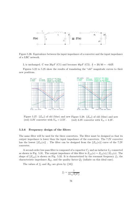
Figure 5.26: Equivalence between the input impedance <strong>of</strong> a converter <strong>and</strong> the input impedance<strong>of</strong> a LRC network.L is unchanged. C was 20µF (C1) <strong>and</strong> becomes 40µF (C2).1γ= 20/40 = −6dB.Figures 5.22 to 5.25 show the results <strong>of</strong> translating the “old” magnitude curves to theirnew positions.Figure 5.27: ‖Z in ‖ <strong>of</strong> old (blue) <strong>and</strong> new(red) 3.3V converter with V in = 2.5V .Figure 5.28: ‖Z in ‖ <strong>of</strong> old (blue) <strong>and</strong> new(red) 3.3V converter with V in = 4.2V .5.3.6 Frequency design <strong>of</strong> the filtersThe same filter will be used for the three converters. The filter must be designed so that itsoutput impedance is lower than the input impedance <strong>of</strong> the converters. The 7.2V converterhas the lowest ‖Z in (s)‖ . The filter can be designed from the ‖Z in (s)‖ curve <strong>of</strong> the 7.2Vconverter.A second-order low-pass filter is composed <strong>of</strong> a capacitor C f <strong>and</strong> an inductor L f connectedas shown in Fig. 5.31. The output impedance <strong>of</strong> this filter is Z out (s) = Z Lf (s)//Z Cf (s). Theshape <strong>of</strong> ‖Z out ‖ is shown on Fig. 5.32. It is characterized by the resonant frequency f f , thecharacteristic impedance R 0f , <strong>and</strong> the quality factor Q f (infinite on this ideal case).The values <strong>of</strong> f f <strong>and</strong> R 0f are given by ([16])f f =12π √ L f C f76


