

Design and Implementation of On-board Electrical Power ... - OUFTI-1
Design and Implementation of On-board Electrical Power ... - OUFTI-1
Design and Implementation of On-board Electrical Power ... - OUFTI-1

You also want an ePaper? Increase the reach of your titles
YUMPU automatically turns print PDFs into web optimized ePapers that Google loves.
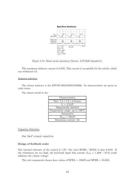
Figure 5.12: Burst mode operation (Source: LTC3528 datasheet).The maximum inductor current is 0.59A. This current is acceptable for the switch, whichcan withst<strong>and</strong> 1A.Inductor selectionThe chosen inductor is the EPCOS B82472P6472M000. Its characteristics are given intable below.The chosen model is theCharacteristicsSize: 7.3 × 7.3 × 4.5(mm)L = 4.7µHMagnetically shieldedTemperature range: up to 150 ◦ CAutomotiveR max = 33mΩSaturation current: 2ACapacitor Selection:<strong>On</strong>e 10µF ceramic capacitors.<strong>Design</strong> <strong>of</strong> feedback scalerThe internal reference <strong>of</strong> the control is 1.2V. The ratio RFBB / RFBA is thus 0.3158. Ifthe resistances are too high, the feed-back input bias current (I F B < 1, 00E − 07A) couldinfluence the output voltage.The real components chosen have values <strong>of</strong> RFBA = 100kΩ <strong>and</strong> RFBB = 31.6kΩ.64


