UMC Installation Manual - Chromalox Precision Heat and Control
UMC Installation Manual - Chromalox Precision Heat and Control
UMC Installation Manual - Chromalox Precision Heat and Control

You also want an ePaper? Increase the reach of your titles
YUMPU automatically turns print PDFs into web optimized ePapers that Google loves.
<strong>UMC</strong> Multiple PowerConnection/Splice/Tee Kit<strong>Installation</strong> InstructionsFor Self-Regulating & Constant Wattage <strong>Heat</strong>ing CablesPJ497-2161-562581-025January, 2012
HAZARD OF ELECTRIC SHOCK. Disconnect all powerbefore opening. All installations must be effectivelygrounded in accordance with the National ElectricalCode to eliminate shock hazard. To avoid electrostaticdischarge, wipe with damp cloth.Turn off power before removing junction box cover atall times.Users should install adequate controls <strong>and</strong> safety deviceswith their electric heating equipment. Wherethe consequences of failure may be severe, back-upcontrols are essential. Although the safety of the installationis responsibility of the user, <strong>Chromalox</strong> willbe glad to assist in making equipment recommendations.Order SeparatelyPipe StrapsPS - 1 (382352) - 1/2” to 3/4” pipesPS - 3 (382360) - 1” to 3-1/2” pipesPS - 10 (382379) - 2-1/2” to 9” pipesCaution Label CL-1 (382424)Fiberglass Tape FT-3 (389941)4
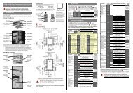
7. Strip each bus wire 1/4”.*Separate CWM leads <strong>and</strong> strip 1/4”from each leadwire.8. Liberally apply RTV over the exposedmatrix <strong>and</strong> leads. Push therubber boot over the heating cable.Trim lead ends as needed.*Boot is not needed when usingCWM constant wattage cable.9. Slide compression fitting over cable.Grommet should be placed insidepipe st<strong>and</strong>off. Termination bootshould be spaced 1/2” from sealinggrommet. Tighten compression fittinguntil it bottoms out against pipest<strong>and</strong>off.10. Assemble junction box to compressionfitting as shown. Tighten locknutuntil the junction box bottomsout against the lip of the compressionfitting.11. Once Locknut is secure place coveron box <strong>and</strong> secure the lid to the boxby tightly fastening screws.12. Attach 3/4” conduit hub. Use a flathead screwdriver to release the terminalspring clamps <strong>and</strong> insert cableleads <strong>and</strong> grounding braid. The <strong>UMC</strong>multiple entry connection kit can beused as a tee kit or a power connectionkit for multiple cables. Pleasesee the electric diagrams below forproper wiring for your application.Attach junction box cover to seal enclosure.Note: The conduit hub should beapproved for Class 1, Div. 2; ClassII Div. 1 & 2, Class III, Div. 1 & 2, <strong>and</strong>NEMA 4X rated by a nationally recognizedtesting laboratory.6
Wiring Diagrams7
Limited Warranty:Please refer to the <strong>Chromalox</strong> limited warranty applicable to this product athttp://www.chromalox.com/customer-service/policies/termsofsale.aspx.1347 HEIL QUAKER BLVD., LAVERGNE, TN 37086Phone: (615) 793-3900 www.chromalox.com© 2012 <strong>Chromalox</strong>, Inc.8