112-J.of Power Sources.2008.pdf
112-J.of Power Sources.2008.pdf
112-J.of Power Sources.2008.pdf

You also want an ePaper? Increase the reach of your titles
YUMPU automatically turns print PDFs into web optimized ePapers that Google loves.
This article appeared in a journal published by Elsevier. The attachedcopy is furnished to the author for internal non-commercial researchand education use, including for instruction at the authors institutionand sharing with colleagues.Other uses, including reproduction and distribution, or selling orlicensing copies, or posting to personal, institutional or third partywebsites are prohibited.In most cases authors are permitted to post their version <strong>of</strong> thearticle (e.g. in Word or Tex form) to their personal website orinstitutional repository. Authors requiring further informationregarding Elsevier’s archiving and manuscript policies areencouraged to visit:http://www.elsevier.com/copyright
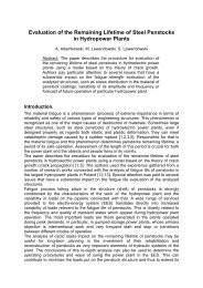
Author's personal copyAvailable online at www.sciencedirect.comJournal <strong>of</strong> <strong>Power</strong> Sources 181 (2008) 41–45Short communicationProduction <strong>of</strong> hydrogen via methane reforming using atmosphericpressure microwave plasmaMariusz Jasiński a,∗ , Mirosław Dors a , Jerzy Mizeraczyk a,ba Centre for Plasma and Laser Engineering, The Szewalski Institute <strong>of</strong> Fluid-Flow Machinery, Polish Academy <strong>of</strong> Sciences,Fiszera 14, 80-952 Gdańsk, Polandb Department <strong>of</strong> Marine Electronics, Gdynia Maritime University, Morska 83, 81-225 Gdynia, PolandReceived 3 September 2007; received in revised form 11 October 2007; accepted 12 October 2007Available online 26 October 2007AbstractIn this paper, results <strong>of</strong> hydrogen production via methane reforming in the atmospheric pressure microwave plasma are presented. A waveguidebasednozzleless cylinder-type microwave plasma source (MPS) was used to convert methane into hydrogen. Important advantages <strong>of</strong> the presentedwaveguide-based nozzleless cylinder-type MPS are: stable operation in various gases (including air) at high flow rates, no need for a coolingsystem, and impedance matching. The plasma generation was stabilized by an additional swirled nitrogen flow (50 or 100 l min −1 ). The methaneflow rate was up to 175 l min −1 . The absorbed microwave power could be changed from 3000 to 5000 W. The hydrogen production rate and thecorresponding energy efficiency in the presented methane reforming by the waveguide-based nozzleless cylinder-type MPS were up to 255 g[H 2 ]h −1and 85 g[H 2 ] kWh −1 , respectively. These parameters are better than those typical <strong>of</strong> the conventional methods <strong>of</strong> hydrogen production (steamreforming <strong>of</strong> methane and water electrolysis).© 2007 Elsevier B.V. All rights reserved.Keywords: Hydrogen production; Methane reforming; Microwave plasma source; Hydrogen production efficiency; Hydrogen production rate; Microwave plasma1. IntroductionMethane or natural gas reforming is widely applied in industryto obtain hydrogen or synthesis gas (H 2 + CO), which thenare utilized, for example as source materials for the production<strong>of</strong> raw chemicals, like methanol and ammonia, and as hydrogenationagents in the oil refinery and reducing gases in thesteel industry. In the last decade, hydrogen gains in importanceas fuel in the fuel cell applications, combustion engines or gasturbines with the goal to achieve a more efficient exploitation <strong>of</strong>energy sources and to reduce noxious emissions.Conventional technologies <strong>of</strong> hydrogen production, i.e. coalgasification, hydrocarbon reforming and water electrolysis, aretoo expensive or not applicable for specific applications due totechnical reasons. Thus, new methods are under development,like water photolysis, biological and plasma methods. Recentlydeveloped microwave plasma sources (MPSs) operated at atmo-∗ Corresponding author. Tel.: +48 58 341 12 71; fax: +48 58 341 61 44.E-mail address: mj@imp.gda.pl (M. Jasiński).spheric pressure [1–6] seem to have a high potential for hydrogenproduction via hydrocarbon reforming.In this paper, a method for production <strong>of</strong> hydrogen viamethane reforming by the use <strong>of</strong> an atmospheric-pressurewaveguide-based nozzleless cylinder-type MPS operated at highgas flow rates is presented.2. Experimental setupThe main parts <strong>of</strong> the experimental setup used in this investigationwere a microwave generator (magnetron), microwaveplasma source (MPS), microwave supplying and measuring system,and gas supplying system (Fig. 1). The microwave power(2.45 GHz, 6 kW) was supplied from the magnetron to the MPSvia a rectangular waveguide (WR-430) having a reduced-heightsection.The waveguide-based nozzleless cylinder-type MPS (Fig. 1)was used for hydrogen production via methane reforming bothwithout and with a catalyst (Fig. 2). As the catalyst an aluminaglobules (φ ≈ 0.5 cm) covered with the nickel oxide wereused. It was a commercial high temperature catalyst (made by0378-7753/$ – see front matter © 2007 Elsevier B.V. All rights reserved.doi:10.1016/j.jpowsour.2007.10.058
Author's personal copy42 M. Jasiński et al. / Journal <strong>of</strong> <strong>Power</strong> Sources 181 (2008) 41–45Fig. 1. Photo <strong>of</strong> the experimental setup with the waveguide-based nozzlelesscylinder-type MPS.Katalizator Sp. z o.o., Kraków, Poland) used in industry formethane steam reforming, which is realized at temperatureabout 800 ◦ C. Since our microwave plasma is <strong>of</strong> temperatureeven higher than 800 ◦ C, we could not use catalysts based onnoble metals, which are destroyed by such high temperature.On the contrary to operating at atmospheric pressure [2,3],there was not any nozzle in our MPS. Instead, the plasma wasgenerated straightforward inside a quartz cylinder, similarly as in[4,5]. The processed methane (up to 175 l min −1 ) was introducedto the plasma by the central duct <strong>of</strong> MPS. The plasma generationwas stabilized by forming an additional swirled nitrogen flow(50 or 100 l min −1 ) in the quartz cylinder. The swirled gas heldthe discharge in the centre <strong>of</strong> the cylinder and thus protected thecylinder wall from overheating. As the swirl the nitrogen wasused instead <strong>of</strong> air to avoid production <strong>of</strong> harmful oxides. Whencatalyst was used, then it was placed in the quartz tube as a pack<strong>of</strong> globules. The pack was fixed 15 cm from the waveguide andits length was about 15 cm.Important advantages <strong>of</strong> the presented waveguide-based nozzlelesscylinder-type MPS are: initiation <strong>of</strong> the discharge withoutany admixture <strong>of</strong> noble gases, stable operation in various gases(including nitrogen, air and methane) at high flow rates, no needfor any special cooling system and for sophisticated impedancematching (e.g., no need for a three-stub tuner).Diagnostics <strong>of</strong> the working gas composition before and afterthe microwave plasma processing <strong>of</strong> methane was carried outusing hydrogen detector (Crowcon XGard), gas chromatograph(SRI 8610C) and Fourier Transform Infrared spectrophotometer(Perkin-Elmer 16 PC).3. ResultsA photo <strong>of</strong> the atmospheric pressure microwave dischargegenerated in methane–nitrogen mixture by the waveguide-basednozzleless cylinder-type MPS is shown in Fig. 3. The innerdiameter <strong>of</strong> the used quartz discharge tube was 26 mm.The dependence <strong>of</strong> the reflection coefficient P R /P I (P R -reflected microwave power, P I -incident microwave power) onincident microwave power P I for different methane flow ratesQ at the best microwave system matching (corresponding to theoptimum position <strong>of</strong> the movable plunger shown in Fig. 1) is presentedin Fig. 4. It seems that the better matching was obtainedfor lower microwave power (e.g., for P I < 4500 W, P R /P I ≈ 5%).Fig. 2. Sketch <strong>of</strong> the waveguide-based nozzleless cylinder-type MPS without(a) and with a catalyst (b).Fig. 3. Photo <strong>of</strong> the atmospheric pressure microwave discharge in methane generatedby the waveguide-based nozzleless cylinder-type MPS. The methaneflow rate (central flow) and the nitrogen flow rate (swirl flow) were 175 and100 l min −1 , respectively. The absorbed microwave power was 4000 W.
Author's personal copyM. Jasiński et al. / Journal <strong>of</strong> <strong>Power</strong> Sources 181 (2008) 41–45 43Fig. 4. The reflection coefficient P R /P I vs. incident microwave power P I fordifferent methane flow rates. The nitrogen swirl flow rate was 50 l min −1 .However, the methane plasma could not be sustained at themicrowave power lower than about 3000 W. More research isneeded to improve the presented MPS performance in terms <strong>of</strong>minimum reflected power.The hydrogen was detected using hydrogen detector and calculatedfrom the balance <strong>of</strong> exit products.Fig. 5 shows FTIR spectrum (a) and chromatogram (b) <strong>of</strong>the working gas mixture after the microwave plasma processingat absorbed microwave power <strong>of</strong> 3000 W, methane flow rate<strong>of</strong> 175 l min −1 and swirl nitrogen flow rate <strong>of</strong> 50 l min −1 .Asitcan be seen from the after-process spectrum and chromatogram,unprocessed methane CH 4 and acetylene C 2 H 2 were found asby-product in the exit gas. The methane decomposed to hydrogenH 2 , acetylene C 2 H 2 and carbon (soot). The soot depositcould be easily noticed on the reactor walls. The soot depositionstarted just after plasma ignition, however not all soot depositedon the reactor walls. Major part <strong>of</strong> the soot was blown <strong>of</strong>f thereactor by the high gas flow. As a result, the thickness <strong>of</strong> the sootlayer deposited on the reactor walls has not exceeded 2 mm anddid not influence the reactor lifetime.For example, at the methane flow rate <strong>of</strong> 175 l min −1 andswirl nitrogen flow rate <strong>of</strong> 50 l min −1 , the production rate <strong>of</strong> thesoot varied from 330 g h −1 (at an absorbed microwave power <strong>of</strong>5000 W) up to 600 g h −1 (at an absorbed microwave power <strong>of</strong>3000 W). At the same conditions, the production rate <strong>of</strong> acetyleneC 2 H 2 was in the range <strong>of</strong> 174–98 g h −1 .As mentioned, the hydrogen production process was carriedout for two cases: without and with catalyst.The energetic parameters <strong>of</strong> the hydrogen production viathe methane reforming, i.e., the production rate <strong>of</strong> hydrogenin g[H 2 ]h −1 and energy efficiency <strong>of</strong> hydrogen production ing[H 2 ] kWh −1 for the case when catalyst was not used can beinferred from Figs. 6 and 7.Fig. 6a and b shows the production rate <strong>of</strong> hydrogen andthe energy efficiency <strong>of</strong> hydrogen production as a function <strong>of</strong>absorbed microwave power for different conditions at methaneFig. 5. FTIR spectra (a) and chromatogram (b) <strong>of</strong> the working gas mixtureafter the microwave plasma processing. Absorbed microwave power: 3000 W,methane flow rate: 175 l min −1 , nitrogen flow rate: 50 l min −1 .flow rate <strong>of</strong> 175 l min −1 . At the best condition, i.e., at the swirlnitrogen flow rate <strong>of</strong> 50 l min −1 and absorbed microwave power<strong>of</strong> 3000 W, the production rate <strong>of</strong> hydrogen and the energy efficiency<strong>of</strong> hydrogen production reached about 222 g[H 2 ]h −1and 74 g[H 2 ] kWh −1 , respectively. Both process parametersdecreased with increasing microwave power. It was caused bychanges in the kinetics <strong>of</strong> the chemical reactions involved. It wasobserved that increasing absorbed microwave power, the length<strong>of</strong> plasma increased. Since a higher microwave power resultsin a higher resident time <strong>of</strong> the processed gas in the plasmaregion, the conversion <strong>of</strong> methane to acetylene exceeded thatto hydrogen when increasing microwave power from 3000 to5000 W.At the swirl nitrogen flow rate <strong>of</strong> 100 l min −1 , the above energeticparameters were about 1.2 times lower than those obtainedat the best condition. This was caused by lower working gas temperature.Addition <strong>of</strong> argon (20 l min −1 ) added to the methaneflow decreased the energetic parameters about three times. Thisresulted from loss <strong>of</strong> the microwave energy in the excitation andionisation processes <strong>of</strong> argon, which do not contribute in themethane conversion reactions.The production rate <strong>of</strong> hydrogen and the energy efficiency<strong>of</strong> hydrogen production versus absorbed microwave power at alower swirl nitrogen flow rate (50 l min −1 ) for different methane
Author's personal copy44 M. Jasiński et al. / Journal <strong>of</strong> <strong>Power</strong> Sources 181 (2008) 41–45Fig. 6. The production rate <strong>of</strong> hydrogen (a) and the energy efficiency <strong>of</strong> hydrogenproduction (b) vs. absorbed microwave power for different conditions. Themethane flow rate was 175 l min −1 .Fig. 7. The production rate <strong>of</strong> hydrogen (a) and the energy efficiency <strong>of</strong> hydrogenproduction (b) vs. the absorbed microwave power for different methane flowrates. The swirl nitrogen flow rate was 50 l min −1 .flow rates are shown in Fig. 7a and b, respectively. As it isseen from these figures, the production rate <strong>of</strong> hydrogen and theenergy efficiency <strong>of</strong> hydrogen production decrease with increasingabsorbed microwave power at higher methane flow rates(175 l min −1 ).At the best condition, i.e. when the flow rates <strong>of</strong> methane andnitrogen were 175 l min −1 <strong>of</strong> 50 l min −1 , respectively, and theabsorbed microwave power was 3000 W, the methane reformingwas carried out also using a catalyst [alumina globules(φ ≈ 0.5 cm) covered with the nickel oxide] as shown in Fig. 2b.The use <strong>of</strong> the catalyst increased both the production rate <strong>of</strong>hydrogen and the energy efficiency <strong>of</strong> hydrogen productionby about 15%, i.e. up to 255 g[H 2 ]h −1 and 85 g[H 2 ] kWh −1 ,respectively. Since initial composition <strong>of</strong> gas processed in ourexperiment is far from that for which the catalyst was designed(i.e., lack <strong>of</strong> water vapour which is a key element in the methanesteam reforming process with nickel-based catalysts), we couldnot expect higher increase.Comparison <strong>of</strong> the energy efficiencies <strong>of</strong> hydrogen productionfor different conventional and plasma methods is given inTable 1. In general, the conventional methods (steam reforming[7] water electrolysis [8]) exhibit lower energy efficiency<strong>of</strong> hydrogen production than plasma methods, except for thedielectric barrier discharge [9]. As seen from Table 1, theenergy efficiency <strong>of</strong> hydrogen production by the conventionalmethods is 3–4 times lower than that in the presented investigation.It is worth mentioning that the method presented by usis more efficient than in other plasma methods operated withouta catalyst (dielectric barrier discharge [9] and gliding arc[10]).At the methane flow rate <strong>of</strong> 175 l min −1 and swirl nitrogenflow rate <strong>of</strong> 50 l min −1 , the total conversion efficiency <strong>of</strong>methane [(CH 4 ) conv /(CH 4 ) tot × 100%] was from about 9.5%(at an absorbed microwave power <strong>of</strong> 5000 W) up to 13.2% (at3000 W), where (CH 4 ) tot is the total (initial) mass <strong>of</strong> CH 4 , and(CH 4 ) conv is the converted mass <strong>of</strong> CH 4 .
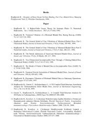
Author's personal copyM. Jasiński et al. / Journal <strong>of</strong> <strong>Power</strong> Sources 181 (2008) 41–45 45Table 1Comparison <strong>of</strong> the energy efficiency <strong>of</strong> hydrogen production via methanereforming for different methods (including our results)Hydrogen productionmethodInitial gas compositionConventional methodsSteam reforming <strong>of</strong> CH 4 +H 2 O + air 20methane [7]Water electrolysis [8] – 21Plasma methodsWaveguide-based CH 4 +N 2 74cylinder-type MPS(our resultswithout catalyst)Waveguide-based CH 4 +N 2 85cylinder-type MPS(our results withcatalyst)Dielectric barrier CH 4 + air 6.7discharge [9]Gliding arc [10] CH 4 +H 2 O + air 40Plasmatron withcatalyst [11]CH 4 +H 2 O + air 225Energy efficiency[g[H 2 ]kWh −1 ]At the methane flow rate <strong>of</strong> 175 l min −1 and swirlnitrogen flow rate <strong>of</strong> 50 l min −1 , the yield <strong>of</strong> hydrogen[H 2 /(2CH 4 ) tot × 100%] was from about 8.7% (at an absorbedmicrowave power <strong>of</strong> 5000 W) up to 12.8% (at 3000 W).At the same conditions, the selectivity <strong>of</strong> hydrogen[H 2 /(2CH 4 ) conv × 100%] was from about 91.9% (at an absorbedmicrowave power −5000 W) up to 96.8% (at 3000 W).When air is used as an additive to methane, as for examplein the methane steam reforming [7], the emission <strong>of</strong> oxide compounds,e.g., carbon oxides and nitrogen oxides, is expected.Our experiment was carried out without any admixture <strong>of</strong> air,thus we avoided emission <strong>of</strong> any oxygen compounds usuallyharmful.4. ConclusionsThe results <strong>of</strong> this investigations show that the production rate<strong>of</strong> hydrogen (up to 255 g[H 2 ]h −1 ) and the energy efficiency <strong>of</strong>hydrogen production (up to 85 g[H 2 ] kWh −1 ) by atmosphericpressure microwave plasma are attractive. The absence <strong>of</strong> oxygencompounds as by-products in the <strong>of</strong>f-gas is highly beneficial.The proposed atmospheric pressure microwave plasma systemfor hydrogen production via methane reforming is expected tobe <strong>of</strong> low cost and effective, and thus promising for applications.AcknowledgementsThis research was supported by the Ministry <strong>of</strong> Scienceand Higher Education (MNiSW) under the programme3020/T02/2006/31 and by R&D Network “EKO-ENERGIA”,IMP PAN Gdańsk.References[1] M. Moisan, G. Sauve, Z. Zakrzewski, J. Hubert, Plasma Sources Sci. Technol.3 (1994) 584.[2] M. Moisan, Z. Zakrzewski, J.C. Rostaining, Plasma Sources Sci. Technol.10 (2001) 387.[3] M. Jasiński, J. Mizeraczyk, Z. Zakrzewski, T. Ohkubo, J.S. Chang, J. Phys.D: Appl. Phys. 35 (2002) 2274.[4] K.M. Green, M.C. Borras, P.P. Woskow, G.J. Flores, K. Hadidi, P. Thomas,IEEE Trans. Plasma Sci. 29 (2001) 399.[5] H.S. Uhm, Y.C. Hong, D.H. Shin, Plasma Sources Sci. Technol. 15 (2006)S26.[6] M. Jasiński, Z. Zakrzewski, J. Mizeraczyk, Proceedings <strong>of</strong> the 16th Symp.on Application <strong>of</strong> Plasma Processes “SAAP2007”, Podbanske, Slovakia,2007, p. 165.[7] P.L. Spath, M.K. Mann, National Renewable Energy Laboratory TechnicalReport, 2001 (NREL/TP-570-27637).[8] http://www.loim.vrn.ru/index.php?m=63&page=58&nm=74&p=.2.3.56.64.70.71.72.73.74.[9] M. Heintze, B. Pietruszka, Catal. Today 89 (2004) 21.[10] J.M. Cormie, I. Rusu, J. Phys. D: Appl. Phys. 34 (2001) 2798.[11] L. Bromberg, D.R. Cohn, A. Rabinovich, N. Alexeev, A. Samokhin, R.Ramprasad, S. Tamhankar, Int. J. Hydrogen Energy 25 (2000) 1157.