BS7200 Operator Software for digifas⢠7100 / 7200 - BIBUS SK, sro
BS7200 Operator Software for digifas⢠7100 / 7200 - BIBUS SK, sro
BS7200 Operator Software for digifas⢠7100 / 7200 - BIBUS SK, sro
You also want an ePaper? Increase the reach of your titles
YUMPU automatically turns print PDFs into web optimized ePapers that Google loves.
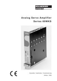
<strong>BS<strong>7200</strong></strong> <strong>Operator</strong> <strong>Software</strong><strong>for</strong> digifas <strong>7100</strong> / <strong>7200</strong>ManualEdition 09/97
Previous editionsEdition Remark12 / 94 First edition, valid <strong>for</strong> software version 4L10/4B20 or higher08 / 95 Valid <strong>for</strong> software version 5L30/5A20, parameters <strong>for</strong> digifas <strong>7100</strong> integrated09 / 96 Valid <strong>for</strong> software version 6L40/6A4005 / 97 Valid <strong>for</strong> software version 7L20/7Axx/7Bxx, valid <strong>for</strong> digifas ® 720609 / 97 SSD versionIBM AT is a registered trademark of International Business Machines Corp.PC AT is a registered trademark of International Business Machines Corp.VGA is a registered trademark of International Business Machines Corp.MS-DOS is a registered trademark of Microsoft Corp.WINDOWS is a registered trademark of Microsoft Corp.digifas is a registered trademark of Seidel Corp. (Regd.TM.No 1549070)Technical changes to improve the per<strong>for</strong>mance of the softwaremay be made without prior notice!Printed in the Federal Republic of Germany 05/97Mat. no. 83107All rights reserved. No part of this work may be reproduced in any <strong>for</strong>m (by printing, photocopying,microfilm or any other method) or stored,processed, copied or distributed by electronic meanswithout the written permission of Seidel Corporation.
09.97-7L20<strong>Software</strong> <strong>BS<strong>7200</strong></strong>Contents Diagram PageIII.3 Menu page “Speed controller". ..................................................III-10III.3.1 Kp, P-gain ..............................................................III-10III.3.2 Tn, integration time .......................................................III-10III.3.3 PID-T2, second time constant. ..............................................III-10III.3.4 SW offset. ..............................................................III-10III.3.5 SW ramp + .............................................................III-10III.3.6 SW ramp - ..............................................................III-11III.3.7 Speed limit .............................................................III-11III.3.8 DC monitor .............................................................III-11III.3.9 Limit switch / Stop ........................................................III-12III.3.10 Start Phi, phase shift ......................................................III-12III.3.11 Limit Phi, phase shift ......................................................III-12III.3.12 T-Tacho, actual speed value filter ............................................III-12III.3.13 Speed steadiness ........................................................III-12III.4 Menu page “General" .........................................................III-13III.4.1 Language ..............................................................III-13III.4.2 No. of motor poles. .......................................................III-13III.4.3 No. of resolver poles ......................................................III-13III.4.4 Position output ..........................................................III-13III.4.5 I/O ....................................................................III-14III.4.6 Ballast resistor (only <strong>for</strong> digifas 7103...7116) .................................III-15III.4.7 Ballast power. ...........................................................III-15III.4.8 Control of motor holding brake ..............................................III-15- A.4.012.3/2III.5 Menu page “Service". .........................................................III-17III.5.1 Parameter update (F2) ....................................................III-17III.5.2 Constant direct current (F5, F9) .............................................III-17III.5.3 Const. speed (F6, F9) .....................................................III-17III.5.4 Const. current (F7, F9) ....................................................III-17III.5.5 Reverse mode (F8, F9) ....................................................III-17III.6 Menu page “Actual values" .....................................................III-18III.7 Menu page “Connect" .........................................................III-18IV Drive optimizationV AppendixV.1 Delivery package, storage, disposal ...............................................V-1V.2 Fault-finding ..................................................................V-1V.3 Glossary. ....................................................................V-2V.4 Operating parameter list ........................................................V-4V.5 Index .......................................................................V-5ContentsPage-B-Contents
<strong>Software</strong> <strong>BS<strong>7200</strong></strong>Safety instructionsSafety instructions09.97-7L20Warning signs : you must observe the important instructions in the text,which are indicated by the following symbols:hazard from electricityand its effectsgeneral warninggeneral instructionOnly properly qualified personnel are permitted to per<strong>for</strong>m activities suchas transport, installation, commissioning and maintenance. Properlyqualified persons are those who are familiar with transport, installation,assembly, commissioning and operation of the products, and who have theappropriate qualifications <strong>for</strong> their job. The qualified personnel must knowand observe the following standards and directives:IEC 364 and CENELEC HD 384 or DIN VDE 0100IEC Report 664 or DIN VDE 0110national accident prevention regulations or BGV A2Read the available documentation be<strong>for</strong>e carrying out installation andcommissioning. Incorrect treatment of the servo amplifier can lead to injuryto persons or material damage. It is vital that you keep to the technical dataand in<strong>for</strong>mation on connection requirements nameplate anddocumentation).The servo amplifiers contain electrostatically sensitive components whichmay be damaged by incorrect handling. Discharge your body be<strong>for</strong>etouching the servo amplifier. Avoid contact with highly insulating (artificialfabrics, plastic film etc.). Place the servo amplifier on a conductive surface.Do not open the units. Keep all covers and switchgear cabinet doors closedin operation. Otherwise there are deadly hazards with the possibility ofsevere danger to health or material damage.In operation, depending on the degree of enclosure protection, servoamplifiers can have bare components which are live and hot surfaces.Control and power cables can carry a high voltage even when the motor isnot rotating.Never undo the electrical connections of the servo amplifier when it is live.There is a danger of electric arcing and danger to persons and contact.Wait at least two minutes after disconnecting the servo amplifier from themains supply voltage be<strong>for</strong>e touching live sections of the equipment orundoing connections (e.g. contacts, screwed connections). Capacitors canhave dangerous voltages present up to two minutes after switching off thesupply voltages. To be sure, measure the voltage in the intermediate circuitand wait until it has fallen below 40V.Safety instructions Page - C -
Directives and standardsDirectives and standards09.97-7L20<strong>Software</strong> <strong>BS<strong>7200</strong></strong>Servo amplifiers are components which are intended to be incorporated into electrical machinesand plant.When the servo amplifiers are incorporated into machines or plant, the intended operation ofthe amplfiers is <strong>for</strong>bidden until it has been established that the machine or plant fulfills therequirements of the EC Directive on Machines 89/392/EEC and the EC Directive on EMC89/336/EEC. EN 60204 and EN 292 must also be observed.In connection with the Low Voltage Directive 73/23/EEC, the harmonized standards of theEN 50178 series are applied to the servo amplifiers, together with EN 60439-1, EN 60146and EN 60204.The manufacturer of the machine or plant is responsible <strong>for</strong> ensuring that the machine or plantmeets the limits which are laid down by the EMC regulations. Advice on the correct installation<strong>for</strong> EMC – such as shielding, grounding, arrangement of filters, treatment of connectors and layingout the cabling – is included in the documentation of the used servo amplifier.Page-D-Directives and standards
<strong>Software</strong> <strong>BS<strong>7200</strong></strong>09.97-7L20IGeneral In<strong>for</strong>mationI.1 PrefaceThis manual explains the installation and application of the operator software <strong>BS<strong>7200</strong></strong><strong>for</strong> the digital servo amplifier digifas <strong>7100</strong>/<strong>7200</strong>.It describes all the parameters, their modes of operation and the methods of optimizing the drivewith the aid of the operator .The manual is divided into 5 chapters:Chapter 1: General In<strong>for</strong>mationChapter 2: Installation /Screen layout / OperationChapter 3: Description of parametersChapter 4: Drive optimizationChapter 5: AppendixKnowledge of the MS-DOS operating system and the use of a personal computer isassumed. You must follow the safety, installation and commissioning instructions inthe installation manual <strong>for</strong> the particular servo amplifier which is used.We provide training and familiarization courses on request.Only professional staff with extensive knowledge of drive and control technologyare allowed to use the operator software (or the operating keys) to alter theoperational parameters of the servo amplifier.I.2 Further documentationInstallation manual <strong>for</strong> the digifas <strong>7100</strong> servo amplifier Order no. 83498Installation manual <strong>for</strong> the digifas <strong>7200</strong> servo amplifier Order no. 83003Digital interfacing with the automation system:Technical description BIT CONNECT Order no. 83108Technical description PROFIBUS CONNECT Order no. 83106Technical description PULSE CONNECT Order no. 83109Technical description CAN CONNECT Order no. 83105All the operating manuals <strong>for</strong> the component parts are delivered together with the amplifier.I.3 Use as directedThe <strong>BS<strong>7200</strong></strong> software is intended to be used to alter or to store the operational parametersof the digifas series of servo amplifiers. The servo amplifiers which are connected arecommissioned with the aid of the software. During this procedure the drive is under the directcontrol of the service functions.Online parameterization of a drive which is running is only permissible <strong>for</strong> professional personnel.The software does not provide any personal or material safety. You must there<strong>for</strong>eensure that the higher level control provides a safe monitoring of the drive.Prepare a hazard analysis of your machine.Data sets which are stored on data media are not safe from undesired alteration by third parties.After loading a set of data it is there<strong>for</strong>e necessary to check all parameters thoroughly be<strong>for</strong>eenabling the servo amplifier.Chapter I General In<strong>for</strong>mation Page I-1
09.97-7L20<strong>Software</strong> <strong>BS<strong>7200</strong></strong>I.4 Abbreviations usedAbbrev. Meaning Abbrev. MeaningCOM Serial interface of a PC-AT MS-DOS Operating system <strong>for</strong> PC-ATDisk Magnetic storage (diskette, hard disk) PC-AT Personal computer with 80x86 processorEEPROM Electrically erasable read-only memory RAM Volatile memoryLPT Parallel interface of a PC-AT VGAMBMegabyte ( 1 million bytes)Graphics output with at least640x480 pixelsI.5 <strong>Software</strong> descriptionThe digital servo amplifiers of the digifas <strong>7100</strong>/<strong>7200</strong> series must be adapted to thecharacteristics of your machine. Do not carry out the parameterization directly on the amplifier,but with the aid of the operator software <strong>BS<strong>7200</strong></strong>, running on a personal computer. The PC isconnected to the servo amplifier by a special cable. The operator software establishes the communicationbetween the PC and the digifas, and exchanges data and instructions.You will find the operator software on the enclosed diskette.Keep the diskette safe in a place which is protected from dust, dampness,magnetic fields and extreme temperatures.Never put the diskette in a switchgear cabinet or a cable duct.The magnetic fields in such areas may destroy the magnetization of the diskette.Use only a copy of the original diskette on site.You can change all the parameters, with very little ef<strong>for</strong>t, and instantly observe the effect on thedrive, since there is a continuous on-line connection to the amplifier .Important process values (actual values) are simultaneously read in from the amplifier anddisplayed on the monitor of the PC.Any interface modules (CONNECT modules) which are built in to the amplifier will be automaticallyrecognized and the additional parameters which are required <strong>for</strong> positional control or amotion block will be made available.If there is no amplifier connected to the PC then it is still possible to start the software, but theresponse to keyboard entry will be considerably delayed, because every attempt at communicationbetween the PC and the amplifier will result in a time-out error message after the maximumwaiting time. In this case, use the “Offline editing” mode (menu page: Handling). In thismode the communication is switched off and you can work without any delays.Sets of data can be stored on data storage media (<strong>for</strong> archiving) and loaded again. Data sets onstorage media can also be printed out.We provide motor-oriented default data sets <strong>for</strong> all plausible combinations of servo amplifier andmotor (6SM motor series). In many applications you will be able to use these default values tocommission your drive without any problems .neue seitePage I-2 General In<strong>for</strong>mation Chapter I
<strong>Software</strong> <strong>BS<strong>7200</strong></strong>09.97-7L20IIII.1Installation / OperationInstallation under DOSFirst check that your PC fulfills the system requirements (see Chapter I.6).The operator software will be found on the enclosed diskette, with the name<strong>BS<strong>7200</strong></strong>.EXEThe diskette also includes an installation program called SETUP.BAT, which makes it easier<strong>for</strong> you to install the operator software onto your PC.Connection to a parallel Port of the PC:Plug in the communications cable (with the 25-pin SubD male) to a parallel port (printerinterface) on your PC, and plug the 9-pin SubD connector into the PC interface of the digifas.Connection to a serial Port of the PC:Plug in the communications cable (with the 9-pin SubD female) to a serial port on your PC, andplug the 9-pin SubD connector into the PC interface of the digifas.Switch on :Switch on the PC-AT and the monitor.After booting up, the MS-DOS prompt will appear on the screen, usually as the “>” symbol.Take the diskette which contains the operator software out of its protective sleeve and insert itinto the slot of the diskette drive.Enter the following commands on the keyboard:a: (or b:) Select diskette drive A or B, according to which one holds the diskette. Press ReturnsetupStart of the installation program Press ReturnThe installation program will now create a directory called DIGIFAS on your C drive, with subdirectoriescalled DAT and DEFAULT, and will copy the program and the files of default values tothe corresponding directories.II.2Program startWhen the SETUP program has finished you will be in the directory C:\DIGIFASbs<strong>7200</strong> LPT1bs<strong>7200</strong> LPT2bs<strong>7200</strong> COM1bs<strong>7200</strong> COM2Call the program <strong>BS<strong>7200</strong></strong>.EXE when the connection is to LPT1:Call the program <strong>BS<strong>7200</strong></strong>.EXE when the connection is to LPT2:Call the program <strong>BS<strong>7200</strong></strong>.EXE when the connection is to COM1:Call the program <strong>BS<strong>7200</strong></strong>.EXE when the connection is to COM2: Press ReturnThe operator software has now been installed and started.To exit the operator software : press the ESC key and confirm the query with “Y”If the program does not function, the computer crashes, or unexpected effects occur, thenyou should use the program BOOTDI<strong>SK</strong>.COM to create a boot disk (see Chapter II.3)neue seiteChapter II Installation / Operation Page II-1
09.97-7L20<strong>Software</strong> <strong>BS<strong>7200</strong></strong>II.3Creating a boot diskIf the <strong>BS<strong>7200</strong></strong> program does not function, the computer crashes, or unexpected effects occur,then you should use the program BOOTDI<strong>SK</strong>.COM to create a boot disk. The system configurationof your PC is probably not suitable <strong>for</strong> working with <strong>BS<strong>7200</strong></strong>.EXE.Insert a blank, <strong>for</strong>matted diskette into the A: drive.Start the BOOTDI<strong>SK</strong>.COM program. This program copies the operating system files from yourhard disk to the diskette. Two start files which we have created (config.sys and autoexec.bat)are also copied to the diskette.You now have a bootable diskette which will start your PC with a minimal system configuration.Now press the RESET button on your PC. The PC will start up with the system configurationwhich is on the diskette. The <strong>BS<strong>7200</strong></strong> operator software will be started automatically.When you close the <strong>BS<strong>7200</strong></strong> program you will find yourself to be in the C:\DIGIFAS directory.If you want to start up the PC in the original configuration, remove the diskette from the A: driveand operate the RESET button again. The PC will now start up with the system configurationwhich is on the hard disk.II.4Other operating systemsWINDOWS 3.xx and WINDOWS 95<strong>BS<strong>7200</strong></strong>.EXE is a DOS program. You can only run it under WINDOWS as a full-screen DOSsession, not in a window. Please consult the WINDOWS documentation.WINDOWS NT<strong>BS<strong>7200</strong></strong>.EXE is not executable under WINDOWS NT.OS2<strong>BS<strong>7200</strong></strong>.EXE ist not intended to be used under OS2.Network<strong>BS<strong>7200</strong></strong>.EXE is not intended to be used in networks.neue seitePage II-2 Installation / Operation Chapter II
<strong>Software</strong> <strong>BS<strong>7200</strong></strong>09.97-7L20 - A.4.024.3/3II.5Screen LayoutThe screen layout is shown below, using the “SPEED” menu page as an example.Menu bar (line 1) : All the screen pages which can be selected are displayed inclear text in the header line of the screen.Current menu item : The current menu selection is shown in a different colour.Input limits : If a parameter is selected (e.g. “SW Offset”), then thepermissible limits <strong>for</strong> the input are shown here.Amplifier status : Displays the current servo amplifier status.(line 2)Interpretation of the field at the far right:Comm.fault Communications fault amplifier PCAmpl.fault In input mode: indicates the availability ofa detailed error message in the third lineof the screen.This detailed message in the error/statusline is only visible in the command mode.Status : In input mode: if a situation occurs whichwould affect the functioning of the drive, thisindicates the availability of a detailed errormessage in the third line of the screen.This detailed message in the fault/statusline is only visible in the command mode.Offline : Parameter Offline editing is set to “on”.The parameters which are displayed willno longer be transferred to the digifas .Input field : Input field <strong>for</strong> altering parameters (only in input mode)Act. value parameter : Display field <strong>for</strong> parameters (only in input mode)Error/Status line 3 : Servo amplifier faults, communications errors and statusmessageswhich would affect operation are displayedin this line (only in command mode).Actual values : Actual values of the servo amplifier are displayed in on-line mode.<strong>Operator</strong> keys : The operator keys which are currently available <strong>for</strong> use. -A.4.024.3/3Chapter II Installation / Operation Page II-3
09.97-7L20<strong>Software</strong> <strong>BS<strong>7200</strong></strong>II.6OperationThe opening screen appears after the start of the operator program. Please observe the safetyand commissioning instructions in the instruction manual <strong>for</strong> the servo amplifier be<strong>for</strong>e using theoperator software.Press thekey.The standard screen page now appears and the menu item “HANDLING” is active. You are nowin the command mode. A distinction is made between command and input mode.In command mode a menu item can be selected. Use the ALT key <strong>for</strong> this purpose, hold itdown and in addition press the key with the underlined letter <strong>for</strong> the desired menu item(e.g. ALT-C <strong>for</strong> the CURRENT menu). After selecting a menu item you will still be in thecommand mode. You can reach the command mode from within the input mode by usingESC or the function key F10.Parameters can be altered in the input mode. After altering a parameter you will still be in theinput mode. You can reach the input mode from the command mode by pressing the or keys.It is possible to switch directly from the input mode to a different screen page (corresponding tothe selection of a menu item in the command mode). To do this, press the ALT key, hold itdown, and in addition press the key with the underlined letter <strong>for</strong> the desired menu item.If you are in input mode (i.e. a parameter field is marked by a colour), you can access the previousor following parameters by pressing the or keys.There are different types of parameter:Numerical parameters— e.g. SW1 Offset in the SPEED menu page. The inputfield appears at the left in the third line of the screen.The input limits are displayed in the middle of thisscreen line.Input: Digits and point as decimal characters.Press to confirm the entry.Selection parameters— e.g. DC Monitor in the SPEED menu page. Theseparameters are identified by a small triangle in frontof the parameter field (if it has been selected).No input field appears. The available options aredisplayed in the middle of the third line of the screen.Input: Selection by using the or keys. Thespacebar can also be used, instead of the key.Function calls — e.g. “save to EEPROM” on menu page “Handling”.The function is started by entering Safety queries prevent accidental execution.All entries are subjected to a plausibility check. If the result is not satisfactory the entry isrejected and the error is displayed (at the right of the third screen line). If the entry is plausiblethe new value is transferred to the servo amplifier RAM. After the successful transfer theentered value is transferred to the display field <strong>for</strong> the parameter and then becomes effective.End program — in command mode: press the ESC key— in input mode: press the F10 key, then ESCor two times ESCPage II-4 Installation / Operation Chapter II
<strong>Software</strong> <strong>BS<strong>7200</strong></strong>09.97-7L20II.7Function keysThe usable function keys are displayed in the bottom line of the screen, depending on the programstatus. These keys are assigned to the following functions:F1 key : Help. Input mode : The help text which refers to the current parameterappears in the lower right quarter of the screen.Command mode : Display general in<strong>for</strong>mation.F2 key : Parameter update. The parameters are freshly transferred from amplifier to PC.F5 key : Constant direct current. The drive is run with the preselected parameters“Setpoint” and “electr. angle” from the “SERVICE” menu page. “I_DC” appearsin the third field of the status line. This function remains active until thefunction key F9 is pressed.F6 key : Constant speed. The drive is operated at the predetermined speed givenin the “SERVICE” menu page. “N_CONST” appears in the third field of thestatus line. The function remains active until the function key F9 is pressed.F7 key : Constant current. The drive is operated with the current (1:1) which isselected in the “SERVICE” menu page. “I_CONST” appears in the third fieldof the status line.The function remains active until the function key F9 is pressed.F8 key : Reversing mode. The drive is operated with the preselected “Setpoint”and “Time” parameters in the “SERVICE” menu page.“REVERS” appears in the third field of the status line.The function remains active until the function key F9 is pressed.F9 key : Stop (OFF): The functions F5, F6, F7 and F8 are switched off by using this key.F10 key, ESC: End input mode, change to the command mode.Any confirmation queries appear in the third line of the screen. Answer the queries by using theY <strong>for</strong> YES or the N key <strong>for</strong> NO.Only use the F6, F7 and F8 functions when you are sure that the movement of the drivecannot lead to any hazard <strong>for</strong> persons or machinery.Be<strong>for</strong>e answering the confirmation query with YES, check whether the parameterswhich have been entered <strong>for</strong> the function in the “SERVICE” menu page are correct.II.8 Status line, screen line 2The current status of the servo amplifier which is connected is continually displayed in elevenfields in the status line (second screen line). The line is structured as follows, from left to right:Field 1 : Type of servo amplifierField 2 : State of the ENABLE inputField 3 : Operating mode: displays the type of the integrated interface moduleor the per<strong>for</strong>mance of a test function (F5, F6, F7 or F8 keys)Field 4 : State of the BTB output of the servo amplifierField 5 : not usedField 6 : not usedField 7 : Displays whether the ballast capacity has been exceededField 8 : Displays whether the I²t threshold has been exceededField 9 : State of the In-Position output (only with an integrated interface module)Field 10 : not usedField 11 : Communication fault, notification of an error message, or other statusmessages in line 3 in command mode (see Chapter II.9).Chapter II Installation / Operation Page II-5
09.97-7L20<strong>Software</strong> <strong>BS<strong>7200</strong></strong>II.9 Error and status messages, screen line 3In command mode, error messages and status messages which restrict operation are displayedin the third line of the screen. In input mode the general message “Ampl. fault” or“Status”appears in field 11 of the status line. After changing to the command mode (F10) the detailedmessages appear in the third line of the screen. The screen line is built up dynamically, theError/status messages appear in the order of their weighting.Error messages (listed in the weighting order):Outp.stage Fault in the output stageResolver Resolver errorUndervolt. Undervoltage in the intermediate voltage (DC link)Overvolt. Overvoltage in the intermediate voltage (DC link)Earth_fault Motor short-circuit to earth (only <strong>for</strong> digifas <strong>7200</strong>)BrakeBrake fault (cable break or similar)Mains_BTB Mains-BTB (no significance)Heat_sink Heat sink temperature too highIntern.temp Internal temperature too highMotor_temp Motor temperature too highEEPROM 1 Read error internal EEPROM. All parameters have been set to 0 !EEPROM 2 Read error CONNECT-interface EEPROM. CONNECT parameters=0 !Time-out Time-out <strong>for</strong> the field-bus master station.Motor cable Phase U or phase V of the motor cable is interruptedLCAinternal messageAll error messages result in the opening of the BTB-contact and the switch-off of theoutput stage of the servo amplifier (no motor current and torque).If a brake is fitted and selected, then the brake will be activated.Status messages (listed in the weighting order):PSTOPNSTOPCont.errorSoft-End-1Soft-End-2message hardware limit switch <strong>for</strong> positive (CW) rotationmessage hardware limit switch <strong>for</strong> negative (CCW) rotationmessage contouring error (with integrated CONNECT interface)message software limit switch 1 (with integrated CONNECT interface)message software limit switch 2 (with integrated CONNECT interface)II.10Actual-value displayThe actual values which are read in on-line from the amplifier are displayed at top right of allscreen pages (apart from the “HANDLING” page):SpeedActual currentAngle of rotationactual speed of the motoractual effective current output (active current)actual angle of rotation of the rotor (only <strong>for</strong> n
<strong>Software</strong> <strong>BS<strong>7200</strong></strong>09.97-7L20IIIIII.1III.1.1Description of parametersMenu page “Handling”Save to EEPROMPermanent storage of the current parameter set in the EEPROM of the servo amplifier.Input :ReturnAfter operating the key, the confirmation query “Execute function Y/N ?” appears.If you reply with “Y”, then the function will be per<strong>for</strong>med.This function is used to write the current parameter set from the servo amplifier RAM to theEEPROM. In this way all the parameter changes which you have made since the lastswitch-on or reset of the servo amplifier are stored permanently.III.1.2Edit OfflineEven when no servo amplifier is connected, you can still display and process data sets.To do this, set the parameter “Offline Editing” to ON. Use the command “Load from disk” to loada set of data. Now you can set all the parameters as usual, and then “Save to disk” to store thedata set.If you have loaded a set of data and then set the parameter “Offline Editing” to OFF, then thedata set which has been loaded will be discarded. If a servo amplifier is connected, then theparameters which are stored in the servo amplifier will be read and displayed.The status “OFFLINE” is displayed in field 11 of the status line (2nd line, at right).Selection : ON, OFFneue seiteIf you have saved data sets with the software version 6L40, or older, and then edit them“Offline” with operator software 7L20, then some program settings will be set automatically,since the appropriate in<strong>for</strong>mation is missing from the old data sets.Chapter III Description of parameters Page III-1
09.97-7L20 - A.4.024.3/6<strong>Software</strong> <strong>BS<strong>7200</strong></strong>III.1.3Select directorySelection or creation of a directory on the hard disk.Input :ReturnDefault setting on delivery: “DAT” directory.Choose the selection or creation of the current directory on the hard disk.Select: Choose one of the first 10 stored directories from the selection window, using the or keys and confirm by pressing . If more than 10 directories areavailable, use the Page or Page keys to go to the previous/followingdirectories.Create: Define a name <strong>for</strong> the directory (max.8 characters: A-Z, 0-9). If the name is correct,then, after a confirmation query, the directory is created and becomes current. -A.4.024.3/6Page III-2 Description of parameters Chapter III
<strong>Software</strong> <strong>BS<strong>7200</strong></strong>09.97-7L20 - A.4.024.3/5III.1.4Save to diskSaves the current parameter set to the current directory on the hard disk.Input:ReturnComplete the input <strong>for</strong>m (name of the data set :max. 8 characters 0...9, A...Z).After operating the key, there is a check whether a data set with this name alreadyexists. If not, then the name is stored, if there is, then the confimation query appears“Overwrite data set Y/N”. If you reply with “Y” , then the data set will be overwritten.See the flow diagram below <strong>for</strong> the functional procedure. - A.4.024.3/5Chapter III Description of parameters Page III-3
09.97-7L20<strong>Software</strong> <strong>BS<strong>7200</strong></strong>III.1.5Load from diskA set of data is read from the data bank on the current hard-disk directory and becomes thecurrent (active) set.Input: Return the servo amplifier must be disabledMake your selection in the selection window with the first 10 stored data sets, using the or key, and accept with . If more than 10 data sets are available, then change to theprevious/following page by using Page or Page . The selection can be rejected by usingthe ESC key.If the type of servo amplifier does not match the selected data, then an error message appearsand the data will not be loaded.For permanent storage of the data in the servo amplifier:per<strong>for</strong>m the function “SAVE TO EEPROM”.Functional procedure: see the following flow diagram.Data sets which are stored on data media are not safe from unwanted alterations by thirdparties. After loading a set of data it is there<strong>for</strong>e necessary to check all parameters thoroughlybe<strong>for</strong>e enabling the servo amplifier.Page III-4 Description of parameters Chapter III
<strong>Software</strong> <strong>BS<strong>7200</strong></strong>- A.4.024.3/409.97-7L20 - A.4.024.3/4Chapter III Description of parameters Page III-5
09.97-7L20<strong>Software</strong> <strong>BS<strong>7200</strong></strong>III.1.6Load default settingsThe default data sets which we provide <strong>for</strong> certain servo amplifier – motor combinations can beloaded into the RAM from a data bank on the hard disk.Input : Return servo amplifier must be disabled, Offline Editing = OFFMake your selection in the selection window with the first 10 stored data sets, using the or key, and accept with . If more than 10 data sets are available, then change to theprevious/following page by using Page or Page . The selection can be rejected by usingthe ESC key.If the type of servo amplifier does not match the selected data, then an error message appearsand the data will not be loaded.The data bank is continually being expanded. The current date of the default data bank can beseen to the right of the selection window.For permanent storage of the data in the servo amplifier, use the function “SAVE TO EEPROM”.Functional procedure: see the following flow diagram.Data sets which are stored on data media are not safe from unwanted alterations by thirdparties. After loading a set of data it is there<strong>for</strong>e necessary to check all parameters thoroughlybe<strong>for</strong>e enabling the servo amplifier.Page III-6 Description of parameters Chapter III
<strong>Software</strong> <strong>BS<strong>7200</strong></strong>- A.4.024.3/1109.97-7L20 - A.4.024.3/11Chapter III Description of parameters Page III-7
09.97-7L20 - A.4.024.3/7<strong>Software</strong> <strong>BS<strong>7200</strong></strong>III.1.7Print parametersData sets which are stored on disk can be printed out. You can select whether the printer dataare sent to a parallel port (LPT1 or LPT2) or saved as a file in the current directory. You can usejust about any commercially available printer – the data are output in 8-bit ASCII <strong>for</strong>mat.The function “Print parameters” can only be selected when the parameter “Offline editing” is setto ON.For functional procedure: see flow diagram below.Input :Return - A.4.024.3/7Page III-8 Description of parameters Chapter III
<strong>Software</strong> <strong>BS<strong>7200</strong></strong>09.97-7L20III.2III.2.1Menu Page "Current controller"I rms , effective currentThis parameter sets the required nominal output current. The value is usually set to thequiescent current I 0 of the attached motor. The upper limit is set automatically, depending onthe type of servo amplifier.This function is used to monitor the actual rms current required. The limit which is defined by theI rms setting will respond after approx. T I2t = 5s at maximum load. The conversion <strong>for</strong>mula <strong>for</strong>current settings which diverge from the rated values is:TI2tI20s Irmspeak2Input : 0,1A...nominal output current of the servo amplifierEffects: Value too low — drive shows a contouring error, torque too lowValue too high — motor may be thermally overloadedIII.2.2I peak , peak currentThis parameter sets the required peak output current (effective value). The upper limit is set automatically,depending on the type of amplifier.The permissible peak motor current I 0max must not be exceeded in any circumstances!Input : 0,2 x ... 2 x the rated servo amplifier currentEffects: Value too low — Drive shows a contouring error, peak torque is too lowValue too high — Drive is at riskIII.2.3I²t messageThis sets a percentage (0 ... 100 %) of the effective current which, if exceeded, results in a signalat the programmable I/O output (terminal X3/15).Input : 0...100 %Effects: Value too low — Message appears too early, drive is under-usedValue too high — Limiting appears simultaneously with the messageIII.2.4Kp, P-gainDetermines the proportional gain (0.1 ... 8) of the current controller.Only alter this parameter if no other measure produces the required controlcharacteristics.Call our Service Department <strong>for</strong> further in<strong>for</strong>mation.III.2.5Tn, integration timeDetermines the integration time constant or reset time (0.1 ... 10 ms) of the current controller.Only alter this parameter if no other measure produces the required controlcharacteristics.Call our Service Department <strong>for</strong> further in<strong>for</strong>mation.Chapter III Description of parameters Page III-9
09.97-7L20<strong>Software</strong> <strong>BS<strong>7200</strong></strong>III.3III.3.1Menu page “Speed controller"Kp, P-gainThis parameter defines the proportional gain (also called AC-gain). Increasing the value until themotor is on the verge of oscillation and then reducing it well below this threshold to avoid oscillation.Typical settings are between 10 and 20.Input : 0,1...63Effects: Value too low — drive is too soft, poor dampingValue too high — drive whistles or runs roughlyIII.3.2Tn, integration timeDetermines the integration time constant. Small motors permit shorter time constants(5...10ms), larger motors or large inertial mass moments usually require time constants of 20 msand more. An entry of 1000 ms effectively turns off the I component.Input : 0,1...1000 msEffects: Value too low — drive runs roughly, strong overshoot withhigh external moments of inertiaValue too high — drive is too softIII.3.3PID-T2, second time constantThis parameter affects the P-gain at medium frequencies. The damping of the speed controlloop can often be improved by increasing PID-T2 to T n /3. If this setting (0.2 ... 25 ms) is necessaryit is made after the basic setting of K p and T n .Input : 0,2...25 msEffects : Value too low — drive is too stiffValue too high — not stiff enoughIII.3.4SW offsetThis parameter is used to compensate <strong>for</strong> the offset voltages in the CNC-control and the analogueinput. The adjustment is made when the axis is stationary and the setpoint =0V.Input : -120 ...+120 mVEffects : Value not correct — axis drifts, even when setpoint =0VIII.3.5 SW ramp +This parameter delays the rate of rise of the setpoint input during acceleration in both directionsby the time entered (up to the maximum value). An advantageous smoothing / limiting ofrate of change is the result in the event of abrupt changes or steps in the setpoint input. The reactiontime of the system will not be impaired, as long as the ramp time is smaller than themechanically limited rise time of the system.Input : 2...6300 ms.Effects : Value too low — ramp function is practically ineffectiveValue too high — ramp function produces contouring errorsPage III-10 Description of parameters Chapter III
<strong>Software</strong> <strong>BS<strong>7200</strong></strong>09.97-7L20III.3.6 SW ramp -This parameter delays the rate of fall of the setpoint input during braking in both directions bythe time entered (up to the maximum value). An advantageous smoothing / limiting of rate ofchange is the result in the event of abrupt changes or steps in the setpoint input.The reaction time of the system will not be impaired, as long as the ramp time is smaller thanthe mechanically limited fall time of the system.Usually, SW ramp + and SW ramp – can be set to the same valueInput : 2...6300 ms.Effects : Value too low — ramp function is practically ineffectiveValue too high — ramp function produces contouring errorsIII.3.7Speed limitDefines the scaling of the speed feedback. The speed limit is reached at the maximum setpointinput of ±10 V.The maximum value depends on the number of resolver poles which is set.no. of resolver polesmax. speed limit2 (without CONNECT) 8000 rpm2 (with CONNECT) 6000 rpm4 (without CONNECT only) 6000 rpm6 (without CONNECT only) 4000 rpmThis setting affects the adjustment of Kp, so the speed limit should be fixed be<strong>for</strong>e theother parameters are adjusted.Input : 800...8000 rpmEffects : Value too low — the required speed limit cannot be reached evenat ±10 V setpoint inputValue too high — the set speed limit cannot be reached, because of thelimited intermediate (link) voltage. The amplifier cuts out.III.3.8DC monitorThe output IDC/VTA (terminal X3/23) provides according to the selection in the operator softwareseveral actual values. The output reistance is 2.2 k, the resolution is 10 bits.Input :Current / Tacho / S_fault / I_setCurrentThe IDC-monitor provides ±10 V <strong>for</strong> ± peak unit current (rms sine-wave value) referred toAGND. The output is the non-phase related actual value of current, which is approximatelyproportional to the motor torque which is produced.TachoThe output provides ±10 V referred to AGND at the set speed limit.The scaling of SW and VTA is there<strong>for</strong>e identical.S_fault (devices with CONNECT interface only)The output provides ±10V <strong>for</strong> the set contouring error referred to AGND.I-setThe output provides ±10V <strong>for</strong> the internal current setpoint (equivalent to ± equipment peak currentat the output of the speed controller) referred to AGND.Chapter III Description of parameters Page III-11
09.97-7L20<strong>Software</strong> <strong>BS<strong>7200</strong></strong>III.3.9Limit switch / StopThe PLC-compatible limit switch inputs can be activated (ON) or deactivated (OFF). An L-signalon the input terminal PSTOP (terminal X3/10) or NSTOP (terminal X3/11) disables the correspondingdirection of rotation. For units without a CONNECT module (i.e without a positioncontrol) braking is made down the setpoint ramp which has been set.The limit switches must remain activated until the motor is at standstill.L-signals on both inputs brake the motor down to a stop. With ON, the motor stops withoutbeing under servo-control. With STOP, the motor stops under drift-free control with standstilltorque M 0 .Input : ON / OFF / STOPEffects : Off — limit switch function is switched offOn — limit switch function is on, motor brakes and stops, noservo control, mechanical release (from stop) permittedStop — limit switch function is switched on, motor stops drift-freewith standstill torque M0III.3.10Start Phi, phase shiftThe inductive phase shift between the motor current and motor voltage at high speeds can becompensated. Under defined voltage conditions this produces a higher torque at the speed limit.Alternatively, the speed limit which can be achieved can be increased by up to 50 %.Input limits: 0 ... speed limit in rpmInput : 0...80% of the set speed limit in rpmEffects : Value too low — motor utilization is worseValue too high — effect is inadequateIII.3.11Limit Phi, phase shiftThe phase shift is increased (depending on the motor speed) linerarly from the Start Phi valueup to the final value = Limit Phi. The optimum setting depends on the motor type and the speedlimit.Input : 0...45 °electricalEffects : Value too low — effect is inadequateValue too high — motor utilization is worse, very high idle currentIII.3.12T-Tacho, actual speed value filterThe time constant of the PT1 filter in the actual speed feedback (tacho smoothing) can be alteredif required. This can produce an improvement in the quietness of running and step response,especially <strong>for</strong> small, highly dynamic motors.Input : 0,2 ... 100 msEffects : Value too low — motor runs roughlyValue too high — speed regulation becomes soft and unstableIII.3.13Speed steadinessImproves the smooth running qualities <strong>for</strong> drive applications with a constant speed.Entry : OFF/ONPage III-12 Description of parameters Chapter III
<strong>Software</strong> <strong>BS<strong>7200</strong></strong>09.97-7L20III.4III.4.1Menu page “General"LanguageSelection of operating language. Input : German, English, FrenchIII.4.2No. of motor polesThe current wave<strong>for</strong>m input can be selected to drive motors with 2 to 12 poles. The motors inthe 6SM series have 6 poles.This parameter can only be changed while the amplifier is disabled(Enable=0). Input : 2,4,6,8,10,12Permitted combinations of no. of motor poles/speed :No. of motor poles No. of resolver poles maximum speed limit2, 4, 6, 8, 10, 12 2 (withou CONNECT) 8000 rpm2, 4, 6, 8, 10, 12 2 (with CONNECT) 6000 rpm4, 8, 12 4 (without CONNECT only) 6000 rpm6, 12 6 (without CONNECT only) 4000 rpmIII.4.3No. of resolver polesStandard resolvers have 2 poles. It is possible to switch over to the use of special versions with4- and 6-poles. This parameter can only be changed while the servo amplifier is disabled.(Enable=0). Input : 2,4,6 (dependent on the setting of “no. of motor poles”)III.4.4Position outputThe position output (connector SubD9-X5) produces according to the adjustment of the parametersbelow a ROD compatible or a synchronous serial position signal.ROD/SSI [-]Selects the type of interface, or switches it off when the position output is not used.Input : OFF, ROD, SSINI offset [increment]Only available if the interface is set to ROD. Determines the position of the zero pulse within aturn at A=B=1. The input is referred to the zero crossing of the resolver and selected resolution.Input : 0...selected resolutionROD code [-]Only available if the interface is set to ROD. Determines whether the output is binary or decimal.Input : binary or decimalResolution [incr./turn]Only available if the interface is set to ROD. Determines the no. of increments per turn whichwill be output. Input : binary 512 / 1024decimal 500 / 1000SSI code [–]Only available if the interface is set to SSI. Selects binary or Gray-code <strong>for</strong>mat as output.Input : binary or GraySSI clock [kHz]Only available if the interface is set to SSI. Selects the SSI-clock rate and the quiescent level ofthe clock line. Input : 200, 1500, 200 inv, 1500 invChapter III Description of parameters Page III-13
09.97-7L20<strong>Software</strong> <strong>BS<strong>7200</strong></strong>III.4.5I/OThis input determines the function of the I/O-terminal (X3/15).Please contact us be<strong>for</strong>e using the functions Ipeak x%, Set/8 or Mains_BTB.The port is programmed as an input or output, depending on which function you select.Input functions :A high signal (24V/7mA, high level = 12 ... 30 V) on terminal X3/15RESET : results in a software-reset (warm boot) of the servo amplifier.All functions and displays are set to their initial state.Parameters which not stored in the EEPROM are erased, and theparameter set which is stored in the EEPROM is loaded.1:1CONTR :produces a 1:1 connection of the speed controller and a switch-off of the actualspeed feedback, i.e. it changes over from speed control to current control.INTG.OFF : results in a switch-off of the integral component of the speed controller.The gain remains at the set value and the actual speed feedback is retained.Ipeak x% : decreases the peak equipment current to x (0...100) %.After selecting the function and pressing the return-key you can enter theparameter “x”.Set/8 : decreases the speed to 1/8 of the limit speed.(not effective with amplifiers with CONNECT Interface).Reference : evaluates the connected reference switch (only effective with amplifiers withCAN CONNECT, PROFIBUS CONNECT oder digilink).Output functions :I²t : When the I²t signal threshold is reached, a high signal (24 V/10mA)isoutputat terminal X3/15 (open collector).BALLAST : An overload of the set ballast capacity is signalled by a high signal(24V/10mA)atterminal X3/15 (open collector).neue seiteMains_BTB :monitors the ready-to-operate signal of the digifas power stage at terminalX3/15 (open collector) with an high signal (24V/10mA).digifas <strong>7100</strong>After switching on the mains voltage the output shows 0V while theintermediate circuit is being loaded.When the intermediate circuit is loaded, 24V is output.If the intermediate voltage drops under 100V, 0V is output.The fault “undervoltage” will not be evaluated.digifas <strong>7200</strong>After switching on the mains voltage the output shows 0V while theintermediate voltage is below 100V.When the intermediate voltage is higher than 100V, 24V is output.If the intermediate voltage drops under 100V, 0V is output.The fault “undervoltage” will not be evaluated.Page III-14 Description of parameters Chapter III
<strong>Software</strong> <strong>BS<strong>7200</strong></strong>09.97-7L20III.4.6 Ballast resistor (only <strong>for</strong> digifas 7103...7116)Selects the ballast resistor which is used.Input : internal / externalIII.4.7Ballast powerLimits the continuous power of the ballast resistor.Input : digifas 7103...7116 200 W with the internal ballast resistordigifas 7103...7116 200...2000 W with an external ballast resistordigifas 7133/7150 200...4000 W, external ballast resistor onlydigifas 7201...7204 1...75 W, internal ballast resistor onlydigifas 7206 free convection : 1...75 W, intern. ballast resistor only<strong>for</strong>ced convection : 76...140 W,intern. ballast resistor onlyEffects : Value too low — the amplifier will produce an “Overvoltage” signalat an early stage in brakingValue too high — ballast resistor can be overloaded.Fire hazard !If the ballast power is set to be higher than the permissible continuous dissipation ofthe externally connected ballast resistor, then the resistor will be thermally overloadedand may burn out.III.4.8Control of motor holding brakeIf a 24 V holding brake in the motor is to be driven directly from the servo amplifier and thebrake option is built into the amplifier, then this parameter can be used to enable the brakefunction.Input :with / withoutwithoutFunction “brake” disabledwithIf the brake function is enabled (WITH), then 24 V (brake off) will be output at theBRAKE terminal (X1/3) when the enable signal is present and 0 V (brake on) if the enablesignal is absent.Because of their design, the holding brakes of the motors require a time of up to 30 ms, dependingon their capacity, to develop the full braking torque.The braking operation is there<strong>for</strong>e controlled as follows:amplifier disabled:amplifier enabled:the brake is applied at once, the amplifier remains active <strong>for</strong> 50 ms(100 ms <strong>for</strong> digifas <strong>7100</strong>) with set value = 0, until it is certain thatthe brake has developed the full torquethe brake is removed at once, the amplifier is immediately enabledThe diagram on the next page indicates the sequential and functional relationship between theENABLE signal, speed setpoint, speed and braking <strong>for</strong>ce.Chapter III Description of parameters Page III-15
09.97-7L20 - A.4.012.3/2<strong>Software</strong> <strong>BS<strong>7200</strong></strong>50ms or 100msDuring the internal ENABLE delay time of 50ms (digifas <strong>7200</strong>) or 100ms (digifas <strong>7100</strong>) thespeed setpoint of the servo amplifier is run down internally to 0Vona10msramp.The activation and release times of the holding brakes which are built into the individual motortypes of the 6SM series are different (see the manual <strong>for</strong> the 6SM motor series).Mains_BTBFunction “BRAKE” disabled. Monitoring of mains voltage active.Connect the output BRAKE (terminal X1/3) with a pull-down resistor (1k) to CNC-GNDif you want to use the function Mains_BTB.Please contact us be<strong>for</strong>e using the function Mains_BTB.digifas <strong>7100</strong>digifas <strong>7200</strong>After switching on the mains voltage the output X3/15 shows 0V while theintermediate circuit is being loaded.When the intermediate circuit is loaded, 24V is output.If the intermediate voltage drops under 100V, 0V is output.The fault “undervoltage” will not be evaluated.After switching on the mains voltage the output X3/15 shows 0V while theintermediate voltage is below 100V.When the intermediate voltage is higher than 100V, 24V is output.If the intermediate voltage drops under 100V, 0V is output.The fault “undervoltage” will not be evaluated. - A.4.012.3/2Page III-16 Description of parameters Chapter III
<strong>Software</strong> <strong>BS<strong>7200</strong></strong>09.97-7L20III.5Menu page “Service"On leaving the program, and after switching the parameter “Offline Editing” to ON, all theservice functions which are active are inhibited.III.5.1Parameter update (F2)The current set of parameters is read out from the memory of the servo amplifier and displayedon the screen. This function is useful <strong>for</strong> amplifiers with a fieldbus interface, which can be parametrizedvia the bus. The screen display can be refreshed by using F2.III.5.2 Constant direct current (F5, F9)The drive is run with adjustable constant-current and electrical angle. The changeover fromspeed to current control is made automatically. This type of setpoint provision only takes effectafter the key F5 has been operated and the confirmation query has been answered with “Y”.The analog setpoint input is out of function.The function is terminated by the function key F9.Input : setpoint : 0 ... +Inom, resolution 0.1 Aelect. angle: 0...359° electr., resolution 1°electr. (the value is adapted,because of the internal data <strong>for</strong>mat)III.5.3 Const. speed (F6, F9)This produces an internal digital fixed-setpoint input, which can be reversed in amplitude andpolarity <strong>for</strong> test purposes. The setpoint does not become active until the function key F6is pressed and the query is confirmed by answering “Y”. The analog input is disabled as longas the function is active. The function is terminated by the function key F9.Input limits: -speed limit ... +speed limit, resolution 0.1 rpmIII.5.4 Const. current (F7, F9)Operates the drive with constant current. The changeover from n- to I-control is made automatically. The setpoint does not become active until the function key F7 is pressed and the query isconfirmed by answering “Y”. The analog input is disabled as long as the function is active. Thefunction is terminated by the function key F9.Input limits: –I nom ... +I nom , resolution 0.1 AIII.5.5 Reverse mode (F8, F9)For operating the drive in reverse mode <strong>for</strong> test purposes, with an adjustable setpoint and reversingtime. The setpoint does not become active until the function key F8 is pressed andthe query is confirmed by answering “Y”. The analog intput is disabled as long as the function isactive. The function is terminated by the function key F9.Input : setpoint : 1...100% of the set speed limit in rpm, resolution 1 %(the value is adapted, because of the internal data <strong>for</strong>mat)time : 50...12000 ms, resolution 50mChapter III Description of parameters Page III-17
09.97-7L20<strong>Software</strong> <strong>BS<strong>7200</strong></strong>III.6Menu page “Actual values"Internal temperatureThe internal temperature is displayed in °C.Heat sink temperatureThe temperature of the heat sink is displayed in °C.Intermediate circuit voltageThe DC-intermediate circuit voltage is displayed in V.I²tThe actual effective (rms) load is displayed in % of the set effective current I rms .Ballast powerThe actual power dissipation in the ballast is displayed in W.SpeedThe actual speed of the motor is displayed in rpm.Actual current valueThe actual effective output current (active current) is displayed in A.Angle of rotationThe indication is the current angular position of the rotor (only <strong>for</strong> n
<strong>Software</strong> <strong>BS<strong>7200</strong></strong>09.97-7L20IVDrive optimizationIn the digifas servo amplifiers current and speed are controlled digitally by the internal amplifiersoftware. In instruments with CONNECT modules the position controller is available as anadditional control loop.The control parameters <strong>for</strong> the individual control loops are set up with the operator software<strong>BS<strong>7200</strong></strong>. The parameters can be found on the following menu pages (see also Chapter III) :Control loop Menu page CommentCurrent controller CURRENT see Chapter III.2Speed controller SPEED see Chapter III.3Position controller CONNECT only if a CONNECT module is installed,the parameters are described in thecorresponding CONNECT manualAll parameters define the real time constants, factors, currents etc. This makes it easier tounderstand their interrelations and the effects which can be achieved.PreparationOscilloscope : connect an oscilloscope between connector X3 (IDC/VTA) and AGND.Reversing mode : in the SERVICE menu pages, set the parameters <strong>for</strong> reversing modeto values which are not dangerous even when the position control loopis switched off (approx. 10 % of the final speed).Analog setpoint : <strong>for</strong> instruments without a CONNECT module, provide a setpoint of 0Vatterminal X3/1-2.For the service function “Reversing mode” the analog setpoint input is switched of<strong>for</strong> the internal position control is disabled.Take care that independent movement of the selected axis is possible without causingany danger. To be safe, operate the ENABLE signal of the amplifier by a confirmation keyand ensure the EMERGENCY STOP function <strong>for</strong> this axis.The control loops function together as a classic cascade control. During optimization you mustproceed in the functional sequence of the control loops :CurrentcontrollerSpeedcontrollerPositioncontrollerOptimizing the current controller (menu page: CURRENT):Load default valuesI peakDisable the amplifier. Load the motor-specific default values(menu page “Handling” : “Load default values”).If the motor/amplifier combination is a good match, then the currentcontroller will already be stable <strong>for</strong> nearly all applications. Parameterswhich are not described below will usually not have to be altered.Reduce I peak to the I nom of the motor, as far as the machine permits.Now enable the amplifier.If the current controller is not stable in operation (the setpoint speed is not reached or the motoroscillates with a frequency clearly above 100 Hz) or the motor which is used is not recorded inthe data bank of default values, please contact our applications department.Chapter IV Drive optimization Page IV-1
09.97-7L20<strong>Software</strong> <strong>BS<strong>7200</strong></strong>Optimizing the speed controller (menu page: SPEED):SW-OFFSETFINAL SPEEDDC-MONITORKp/TnDC-MONITORStartreversing modeLeave the amplifier enabled. If the axis drifts, alter theparameter SW-Offset until it stays still.Set the intended final speed.If the parameter “Final speed” is altered,the influence of Kp is affected in inverse proportion.Set the DC-Monitor to CURRENT.Increase K p until the motor starts to oscillate (audible, and visible onthe oscilloscope), and then reduce K p again until the oscillation hasclearly stopped and stability is assured.Use the motor motor-specific value <strong>for</strong> Tn.Set the DC-Monitor to TACHO.Start the reversing mode (F8). Study the wave<strong>for</strong>m of thetachometer voltage on the oscilloscope. If the setting is correct, astable step response can be observed in both directions.Fig : step responsen = speedn soll = speed setpointSW = setpointt = time1 = optimum2 = Kp to high(adjust PID-T2)KpPID-T2T-TACHOFinishreversing modeSW-RAMP +/-By carefully increasing K p you can make a fine optimization of thespeed response. Aim: minimum overshoot but still good damping.Disturbances, such as slight gearbox play, can be damped out byincreasing PID-T2 to about 1/3 of the value of T n .Especially <strong>for</strong> small drives with low torque: you can improve smoothrunning with T-Tacho.Finish the reversing mode (F9).The position control loop is now closed again.Set the correct motor-specific value <strong>for</strong> I peak again.The setpoint ramps are used to smooth out the setpoint entry (filtereffect). Set the mechanical time constant of the complete system,i.e the rise time of the speed from 0 to n setp .As long as the ramps which are set are shorter than the mechanicalresponse time of the complete system, the response speed will notbe affected. Operate program-controlled motion blocks, and set upthe ramp times to suit.If the drive does not run satisfactorily under position control, look first <strong>for</strong> other causes such as :— mechanical play in the transmission— jamming or stick-slip effects— self-resonant frequency of the mechanical system is too low— poor damping, drive is too weakly dimensionedbe<strong>for</strong>e repeating the optimization of the control loops.Page IV-2 Drive optimization Chapter IV
<strong>Software</strong> <strong>BS<strong>7200</strong></strong>09.97-7L20VAppendixV.1 Delivery package, storage, disposalDelivery package : — 3.5"-diskette with the operator software <strong>BS<strong>7200</strong></strong>, as part of the deliverypackage <strong>for</strong> a servo amplifier of the digifas series— <strong>BS<strong>7200</strong></strong> operating manualStorage :Disposal :— dust, moisture, magnetic or electrical fields, extremetemperatures and incorrect mechanical handling of the diskettecan destroy the data stored on the diskette— only in the original (recyclable) manufacturer’s packaging— storage temperature +10...+60 °C, max. 20 °C/hour variation— humidity relative humidity: max. 95% , no condensation— storage time no limit— Disposal should only be carried out by certified disposal companies.We can give you suitable addresses.V.2 Fault-findingFaultError messageCommunicationfaultpossible cause— wrong PC-cable used— PC-cable plugged in to wrongconnector in servo amp. or PC— wrong PC-port/interface selected— PC driver power insufficient— booster / booster supply defect— mains supply <strong>for</strong> booster is notfunctioning properly— PC is not earthed— I rms or I peak is set too lowmethod of removing the causeof the fault— use a Seidel PC-cable— plug in PC-cable to correctconnector in servo amp/PC— correct operator software call— use booster— replace booster / booster supply— check mains supply— earth PCDrive reports— increase I rms or I peakcontouring(check motor data !)error— setpoint ramp is too steep— reduce SW-ramp +/-Motor is hot — I rms /I peak is set too high — reduce I rms /I peak— Kp (speed controller) is too small— Tn (speed controller) is too largeDrive too soft— PID-T2 is too large— T-Tacho is too large— reduce T-TachoDrive run<strong>sro</strong>ughlyneue seiteAxis drifts whensetpoint = 0V— Kp (speed controller) is too large— Tn (speed controller) is too small— PID-T2 is too small— T-Tacho is too small— offset incorrectly adjusted<strong>for</strong> analog setpoint provision— increase Kp (speed controller)— use motor specific value <strong>for</strong> Tn— reduce PID-T2— reduce Kp (speed controller)— use motor specific value <strong>for</strong> Tn— increase PID-T2— increase T-Tacho— adjust SW-offset(speed controller)Chapter V Appendix Page V-1
09.97-7L20<strong>Software</strong> <strong>BS<strong>7200</strong></strong>V.3 Glossaryneue seiteB Ballast circuit converts excess regenerative energy from the motorduring braking into heat in the ballast resistorC Clock clock signalCommon-mode voltageamplitude of the disturbance which can be eliminatedin an analog input (differential input)CONNECT modulemodule built into the servo amplifier, with integralpositional control, which provides special interfacevariations <strong>for</strong> the connection to thehigher-level controlCountsinternal count pulses, 1 pulse = 1/4096 of 1 turnContinuous ballast poweraverage power which can be dissipated bythe ballast circuitCurrent controllerregulates the difference between the current setpointand the actual current value to 0.output : power output voltageD Disable removal of the ENABLE signal (0V or open)E Earth short electrically conductive connection betweena phase and PEEnableenable signal <strong>for</strong> the servo amplifier (+24V)F Field-bus interface here: CONNECT module CAN-CONNECTand PROFIBUS-CONNECTFinal limit speed max. value of normalized speed at ±10VG GRAY code special <strong>for</strong>m of binary encodingH Holding brake a brake in the motor which must only be activatedat standstillI Input drift temperature and age-dependent changes inan analog inputI²t thresholdmonitoring of the actual effective current demand IrmsIncremental encoder interfaceposition signal by 2 signal with 90° phase difference,not an absolute position signalIpeak, peak currenteffective value of the pulse currentIrms, effective currenteffective value of the continuous currentIntermediate circuitrectified and smoothed power DC voltageK Kp, P-gain proportional gain of a control loopL LC display liquid-crystal displayLimit switchlimit switch <strong>for</strong> the traverse path of the machine;implemented as break contactM Machine the sum of all components which are connectedtogether and of which at least one is movableMains filterexternal device to divert disturbances on the powerleads to PEMonitor outputoutput of an analog measurement valueMotion blockdata packet with all the positional control parameterswhich are required to per<strong>for</strong>m a movement– only when a CONNECT module is availableMulti-axis systemmachine with several independent drive axesneue seitePage V-2 Appendix Chapter V
<strong>Software</strong> <strong>BS<strong>7200</strong></strong>09.97-7L20N Natural convection free air movement <strong>for</strong> coolingNI pulseis produced once per turn by incremental encoders,used to establish the zero point <strong>for</strong> the machineO Optocoupler optical connection between two electricallyindependent systemsP P-controller control loop with purely proportional characteristicPhase shiftcompensation <strong>for</strong> the phase lag between the electromagneticand magnetic fields in the motorPID-Reglera control loop with proportional, integral anddifferential characteristicsPID-T2filter time constant <strong>for</strong> the speed controlPosition controllerregulates the difference between the position setpointand the actual positional value to 0.output : speed setpointPotential isolationelectrically decoupledPower contactorsystem protection with phase-failure monitoringPulse power of the ballast circuitmaximum power which can be dissipatedin the ballast circuitR Reset new start of the microprocessorResolver-digital converterconversion of the analog resolver signalsinto digital in<strong>for</strong>mationReversing modeoperation with a periodic change of directionRing coreferrite ring(s) <strong>for</strong> interference suppressionS Servo amplifier device <strong>for</strong> the control of speedand torque of a servo motorShort-circuithere: electrically conductive connectionbetween two phasesSpeed controllerregulates the difference between the speed setpoint SWand the actual speed to 0.output: current setpointSSI-interfacecyclically absolute, serial positional in<strong>for</strong>mationSW ramplimitation of the rate of changeof the speed setpoint SWT T-tacho, tachometer time constant filter time constant in the speed feedbackof the control loopTachometer voltagea voltage which is proportional to the speedThermal cut-out contacta temperature sensitive switch which isbuilt into the motor windingTn, I-time constantintegral component of the control loopZ Zero pulse is produced once per turn by incremental encoders,used to establish the zero point <strong>for</strong> the machineChapter V Appendix Page V-3
09.97-7L20<strong>Software</strong> <strong>BS<strong>7200</strong></strong>V.4 Operating parameter listGroup Display text Remarks Units Min MaxCurrentcontrollerSpeedcontrollerGeneralDefaultdigifas <strong>7100</strong>Defaultdigifas <strong>7200</strong>I rms effective current A 0.1 I nom 0.5Inom 0.5InomI peak peak current A 0.2xI nom 2xI nom I nom I nomI 2 t treshold monitoring threshold % 0 100 80 80Kp proportional gain - 0.1 8 1.5 1.5Tn integr. time constant ms 0.1 10 0.6 0.6Kp proportional gain - 0.1 63 10 10 (5)**Tn integr. time constant ms 0.1 1000 10(12)* 10 (5)**PID-T2 2. time constant ms 0.2 25 2,0 2,0 (0.6)**SW offset compensation mV -120 +120 0 0SW ramp + ramp up ms 2 6300 10 10SW ramp - ramp down ms 2 6300 10 10final limit speed final tacho speed min -1 800 8000 3000 3000DC monitorFunction X1/3(IDC/VTA)-TACHO/CURRENTS_fehl/I-sollTACHOTACHOLimit switch on/off/stop - off/on stop off offStart Phi Phasen lead min -1 00,8xfinal speed1500 1500Limit Phi Phasen lead °electr. 0 45 20 20T-Tacho tacho time constant ms 0.2 100 0.6 0.6 (0.2)**Speed steadiness speed steadiness - off on off offMotor pole no. steps 2 - 2 12 6 6Language operating language - German Engl./French German GermanRes. pole no. steps 2/4/6 - 2 6 2 2I/Oprogrammableinput/output- various various RESET RESETBallast resistorselect ballast resistor- internal external int.(ext.)* -Ballast power ballast power W various various 200 (860)* 75Brakeunction outputBRAKE-without/withMaisn_BTB without withoutROD/SSI position output - ROD/SSI off ROD RODNI offsetROD zero-pulsepos.Incr. 0 resolution 0 0ROD code ROD output <strong>for</strong>mat - binary decimal bin binResolution ROD resolution Incr/turn 512/1024 500/1000 1024 1024SSI code SSI output <strong>for</strong>mat - binary Gray bin binSSI clock SSI clock rate kHz 200/200 1500/1500 200 200* values in brackets only <strong>for</strong> digifas 7133...7150 ** values in brackets only <strong>for</strong> digifas 7201Customer Cabinet no. Unit no.Place, dateSignaturePage V-4 Appendix Chapter V
<strong>Software</strong> <strong>BS<strong>7200</strong></strong>09.97-7L20V.5 Index! 1:1 control . . . . . . . . . . . . . . . III-142.time constant (PID-T2) . . . . . . . III-10A actual angle of rotation . . . . . . . . III-18actual ballast dissipation . . . . . . . III-18actual current . . . . . . . . . . . . . III-18actual heat sink temperatur . . . . . . III-18actual I²t load . . . . . . . . . . . . . III-18actual intermediate circuit voltage . . III-18actual internal temperatur . . . . . . . III-18actual operating time . . . . . . . . . III-18actual speed . . . . . . . . . . . . . III-18actual-value display . . . . . . . . . . II-6B ballast power . . . . . . . . . . . . . III-15ballast resistor. . . . . . . . . . . . . III-15boot disk . . . . . . . . . . . . . . . II-2brake . . . . . . . . . . . . . . . . . III-15C command mode . . . . . . . . . . . . II-4constant current . . . . . . . . . . . . III-17Constant speed . . . . . . . . . . . . III-17Constanter direct current . . . . . . . III-17create directory . . . . . . . . . . . . III-2current controller . . . . . . . . . . . III-9D DC monitor . . . . . . . . . . . . . . III-11Delivery package . . . . . . . . . . . V-1directory . . . . . . . . . . . . . . . . III-2disposal . . . . . . . . . . . . . . . . V-1Drive optimization . . . . . . . . . . . IV-1E edit offline . . . . . . . . . . . . . . . III-1effective current (Irms) . . . . . . . . III-9error messages . . . . . . . . . . . . II-6F Fault statistics . . . . . . . . . . . . . III-18Fault-finding . . . . . . . . . . . . . . V-1function keys . . . . . . . . . . . . . II-5G Glossary. . . . . . . . . . . . . . . . V-2H Hardware requirements . . . . . . . . I-3humidity . . . . . . . . . . . . . . . . V-1I I/O terminal . . . . . . . . . . . . . . III-14I²t message . . . . . . . . . . . . . . III-9input mode . . . . . . . . . . . . . . II-4Installation DOS. . . . . . . . . . . . II-1integration time (Tn, current) . . . . . III-9integration time (Tn, speed). . . . . . III-10INTG.OFF . . . . . . . . . . . . . . . III-14Ipeak x% . . . . . . . . . . . . . . . III-14I-set . . . . . . . . . . . . . . . . . . III-11L language . . . . . . . . . . . . . . . III-13limit phi . . . . . . . . . . . . . . . . III-12limit switch . . . . . . . . . . . . . . III-12load default settings. . . . . . . . . . III-6load from disk . . . . . . . . . . . . . III-4M Mains_BTB (BRAKE) . . . . . . . . . III-16Mains_BTB (I/O) . . . . . . . . . . . III-14message ballast. . . . . . . . . . . . III-14message I²t . . . . . . . . . . . . . . III-14N NI-offset . . . . . . . . . . . . . . . . III-13no. of motor poles . . . . . . . . . . . III-13no. of resolver poles . . . . . . . . . III-13NSTOP . . . . . . . . . . . . . . . . III-12O Offset . . . . . . . . . . . . . . . . . III-10operating time . . . . . . . . . . . . . III-18operation . . . . . . . . . . . . . . . II-4other operating systems . . . . . . . II-2P parameter list . . . . . . . . . . . . . V-4Parameter update . . . . . . . . . . . III-17path . . . . . . . . . . . . . . . . . . III-2PC cable parallel . . . . . . . . . . . I-4PC cable serial . . . . . . . . . . . . I-4peak current (Ipeak). . . . . . . . . . III-9P-gain (Kp, current) . . . . . . . . . . III-9P-gain (Kp, speed) . . . . . . . . . . III-10phase shift . . . . . . . . . . . . . . III-12position output . . . . . . . . . . . . III-13print parameters. . . . . . . . . . . . III-8PSTOP . . . . . . . . . . . . . . . . III-12R ramp - . . . . . . . . . . . . . . . . . III-11ramp+ . . . . . . . . . . . . . . . . . III-10Reference . . . . . . . . . . . . . . . III-14reset function . . . . . . . . . . . . . III-14resolution . . . . . . . . . . . . . . . III-13reverse mode . . . . . . . . . . . . . III-17ROD/SSI . . . . . . . . . . . . . . . III-13S S_fault. . . . . . . . . . . . . . . . . III-11Safety instructions . . . . . . . . . . 1-Csave to disk . . . . . . . . . . . . . . III-3Save to EEPROM . . . . . . . . . . . III-1Screen layout . . . . . . . . . . . . . II-3select directory . . . . . . . . . . . . III-2Set/8 . . . . . . . . . . . . . . . . . III-14speed controller . . . . . . . . . . . . III-10speed limit. . . . . . . . . . . . . . . III-11speed steadiness . . . . . . . . . . . III-12speed value filter (T-Tacho). . . . . . III-12SSI clock . . . . . . . . . . . . . . . III-13SSI code . . . . . . . . . . . . . . . III-13start phi . . . . . . . . . . . . . . . . III-12status line . . . . . . . . . . . . . . . II-5status messages . . . . . . . . . . . II-6STOP (OFF) . . . . . . . . . . . . . II-5storage . . . . . . . . . . . . . . . . V-1storage temperature . . . . . . . . . V-1storage time . . . . . . . . . . . . . . V-1U Use as directed . . . . . . . . . . . . I-1Chapter V Appendix Page V-5
Vertrieb und Service / Sales and Service / Agence et ServicesBundesrepublik Deutschland /Germany / AllemagneKollmorgen Seidel GmbH & Co. KGVerkaufsniederlassung NordWacholderstr. 40-4240489 DüsseldorfTel.: +49(0)203 - 99 79 214Fax: +49(0)203 - 99 79 182Kollmorgen Seidel GmbH & Co. KGVerkaufsniederlassung WestLilienstraße 342719 SolingenTel.: +49(0)212 -2307799Fax: +49(0)212 -2307797Kollmorgen Seidel GmbH & Co. KGVerkaufsniederlassung MitteBussardweg 3861118 Bad VilbelTel.: +49(0)6101 - 55 866 00Fax: +49(0)6101 - 55 866 06Kollmorgen Seidel GmbH & Co. KGVerkaufsniederlassung Süd-WestLessingstr. 4175015 BrettenTel.: +49(0)7252 - 97 39 040Fax: +49(0)7252 - 97 39 055Kollmorgen Seidel GmbH & Co. KGVerkaufsniederlassung Süd-OstLandsbergerstr. 1786947 WeilTel.: +49(0)8195 - 99 92-50Fax: +49(0)8195 - 99 92-33Servo-DynTechnik GmbHMünzgasse 1001067 DresdenTel.: +49(0)351 - 49 05 793Fax: +49(0)351 - 49 05 794Dänemark / Denmark / DanemarkDIGIMATIC A/S"Laerkenfeldt"Aalkaergaardvej 208700 Horsens NordTel.:+45-75656666Fax: +45 - 75 65 68 33Finnland / Finland / FinlandeDrivematic OYHevosenkenkä 428430 PoriTel.:+358-2-61003311Fax: +358 -2-61003350Frankreich / France / FranceKollmorgen Seidel GmbH & Co. KGParc technologique St.Jacques2 rue Pierre et Marie Curie54320 MaxévilleTel.: +33(0)3 83 95 44 80Fax: +33(0)3 83 95 44 81Kollmorgen Seidel GmbH & Co. KG216 Lotissement Les PeiffendesLe Sonnant d'Uriage38410 UriageTel.: +33(0)4 76 59 22 30Fax: +33(0)4 76 59 22 31Großbritannien /Great Britain / Royaume-UniKollmorgenPO Box 147, KEIGHLEYWest Yorkshire, BD21 3XETel.: +44(0)15 35 - 60 76 88Fax: +44(0)15 35 - 68 05 20Heason Technologies GroupClaremont LodgeFontwell AvenueEastergate Chichester PO20 6RYTel.: +44(0)12 43 - 54 54 00Fax: +44(0)12 43 - 54 45 90Italien / Italy / ItalieM.C.A. s.r.l.Via f. Turati 2120016 Pero (Mi)Tel.: +39(0)02 - 33 91 04 50Fax: +39(0)02 - 33 90 85 8Niederlande /Netherlands / Pays-BasDynamic DrivesWattstraat 26f2723 RC ZoetermeerTel.: +31(0)79 - 59 39 214Fax: +31(0)79 - 59 39 840Schweden / Sweden / SuédeSDT AB25467 HelsingborgTel.: +46(0)42 - 380 800Fax: +46(0)42 - 380 813Stockholm12030 StockholmTel.: +46(0)8 - 640 77 30Fax: +46(0)8 - 641 09 15Göteborg42671 Västra FrölundaTel.: +46(0)31 - 69 62 60Fax: +46(0)31 - 69 62 69Schweiz / Switzerland / SuisseKollmorgen Seidel GmbH & Co. KGBuhnrain 308052 ZürichTel.: +41(0)1 - 300 29 65Fax: +41(0)1 - 300 29 66Spanien / Spain / EspagneBROTOMATIC S.L.C/San Miguel de Acha, 2 Pab.301010 Vitoria (ALAVA)Tel.: +34 945 - 24 94 11Fax: +34 945 - 22 78 32Systempartner / System partners / Partenaires du systémeBundesrepublik Deutschland /Germany / AllemagneWerner P. HermesIngenieurbüroTurmstr. 2340750 LangenfeldTel.: +49(0)212 - 65 10 55Fax :+49(0)212 - 65 10 57EAT GmbHElektronische AntriebstechnikHanferstraße 2379108 FreiburgTel: +49(0)761 - 13 03 50Fax:+49(0)761 - 13 03 555IBK Ingenieurbüro Keßler GmbHDachtmisser Str. 1021394 KirchgellersenTel: +49(0)4135 - 12 88Fax:+49(0)4135 - 14 33MACCON GmbHKühlbachstr. 981543 MünchenTel: +49(0)89 - 65 12 20-0Fax:+49(0)89 - 65 52 17Großbritannien /Great Britain / Royaume-UniMotor Technology Ltd.Unit 1Chadkirk Industrial EstateOtterspool RoadRomiley, StockportCheshire <strong>SK</strong>6 3LETel.: +44(0)161 - 42 73 641Fax : +44(0)161 - 42 71 306Niederlande /Netherlands / Pays-BasKiwietIngenieurbüroHelenaveenseweg 355985 NK Panningen (Grashoek)Tel.: +31(0)77 - 30 76 661Fax: +31(0)77 - 30 76 646Schweiz / Switzerland / SuisseBobry Servo Electronic AGZentralstr. 66030 EbikonTel.: +41(0)41- 440 - 77 22Fax : +41(0)41 - 440 - 69 43Ungarn / Hungary / HongrieQ-TECH Mérnöki Szolgáltató Kft.1161 BudapestBatthyány u. 8.Tel.: +36 (1) 405 - 33 38Fax: +36 (1) 405 - 91 34Italien / Italy / ItalieServo TecnicaViale Lombardia 2020095 Cusano Milanino (MI)Tel.: +39 (0)02 - 66 42 01Fax: +39 (0)02 - 66 40 10 20Türkei / Turkey / TurquieRobotek Otomasyon TeknolojileriAli Nihat Tarlan CAD.Kartal Sk. No: 16/7Üstbostancý ÝSTANBULTel: +90 216 464 50 64 pbxFax: +90 216 464 50 72Griechenland / Greece / GrèceAlpha Motion5 - 7 Alkamenoys Str.104.39 AthensTel.: +30 1 82 27 470Fax: +30 1 82 53 787Australien / Australia / AustralieMotion Technologies PTY. Ltd.1/65 Alexander AvenueTaren Point NSW 2229SydneyTel.: +61 (0)295 24 47 82Fax: +61 (0)295 25 38 78Kollmorgen Seidel GmbH & Co. KGKollmorgenHausanschrift Postanschrift Motion Technologies GroupWacholderstr. 40-42 Postfach 34 01 61 201 Rock RoadD - 40489 Düsseldorf D-40440 Düsseldorf Rad<strong>for</strong>d, VA 24141, USATel.: +49(0)203 - 99 79 - 0 Tel.: +1 540 - 639 - 24 95Fax: +49(0)203 - 99 79 - 155 Fax: +1 540 - 731 - 08 47Internet : http://www.kollmorgen-seidel.deInternet : http://www.kollmorgen.com


