ENT-PT - Community Professional Loudspeakers
ENT-PT - Community Professional Loudspeakers
ENT-PT - Community Professional Loudspeakers

You also want an ePaper? Increase the reach of your titles
YUMPU automatically turns print PDFs into web optimized ePapers that Google loves.
7. Attach the Extension Bracket assembly to the Top Angle Bracket using M6 x 16mm screws, flat washers, lock washers, andnuts. Tighten securely.8. Attach the Bottom Bracket to the Bottom Fitting at the bottom of the “T” Mounting Bracket using the M10 x 20mm bolt, lockwasher, and flat washer.9. Place the Pan-Tilt Bracket assembly on the wall where the <strong>ENT</strong>ASYS array is to be installed. Mark the positions on the wallwhere the holes in the Pan-Tilt Bracket are located.10. Remove the Pan-Tilt Bracket assembly from the wall and properly prepare the wall to accept the correct type of bolts withwhich to attach the Pan-Tilt Bracket assembly to the wall.11. Attach the Pan-Tilt Bracket assembly to the wall using the proper bolts for the wall material and the weight of the <strong>ENT</strong>ASYSarray to be mounted.12. Slide the bottom <strong>ENT</strong>ASYS loudspeaker onto the “T” Mounting Bracket. Tighten all eight of the M4 Set Screws on the <strong>ENT</strong>ASYSenclosure. Place each additional <strong>ENT</strong>ASYS enclosure on the “T” Mounting Bracket in the desired order. Tighten all eight of theM4 Set Screws for an enclosure before another <strong>ENT</strong>ASYS enclosure is placed on top of it. Any Dual Banana Plug Jumpersshould be placed into position during this step.13. Loosen the M6 screw on the outside portion of the Locking Bar. This will allow the array to pivot to point toward the desiredlocation. Aim the array and then tighten the M6 screw on the Locking Bar.14. Securely tighten the M10 bolts on the Top Wall Bracket and the Bottom Bracket.A bracket cover is also provided to help maintain a cosmetically appealing installation. This cover consists of two pieces of black orwhite PVC extrusion. These should each be cut to the required length and then placed above and below the Extension Bracketassembly as shown in Figure 5. The two pieces of extrusion will snap together to enclose the Extension Bracket assembly and hidethe hardware.Figure 5: Pan-Tilt Bracket - Cover Assembly<strong>ENT</strong>-<strong>PT</strong><strong>ENT</strong>ASYS Combination Pan-Tilt Bracket KitCombination Pan-Tilt Bracket Kit for <strong>Community</strong>’s <strong>ENT</strong>ASYS Column LineArray SystemThe <strong>ENT</strong>ASYS Pan-Tilt Bracket Kit, designated <strong>ENT</strong>-<strong>PT</strong>, is used to provide a down-tilt angle (rotation about ahorizontal axis) and a panning action (rotation about a vertical axis) when an <strong>ENT</strong>ASYS column or tall array ismounted to a wall. The Pan-Tilt Bracket Kit consists of two primary parts, a Top Assembly and a Bottom Piece, asshown in Figure 4. The Top Assembly consists of multiple parts that are configured and assembled to yield thedesired down angle for an array of up to five columns. After the Pan-Tilt Bracket Assembly is put together it ismounted to a wall and then the <strong>ENT</strong>ASYS loudspeaker(s) are attached to it. The Pan-Tilt bracket can be used with aone, two, or three column array for a down-tilt angle of up to 10°. With a four or five column array the maximumdown-tilt angle is 5°. All parts in the kit are engineered to provide a high margin of safety when used in accordancewith these instructions. The brackets are manufactured of steel and are covered with a durable powder-coat finish.Kits are available in either black or white to match the color of the enclosures.Table 1: Pan-Tilt Bracket Kit Part NumbersPart No.<strong>ENT</strong>-<strong>PT</strong><strong>ENT</strong>-<strong>PT</strong>WDescription<strong>ENT</strong>ASYS Pan-Tilt Bracket, Black<strong>ENT</strong>ASYS Pan-Tilt Bracket, WhiteNo hardware is provided to attach the <strong>ENT</strong>ASYS column assembly and Pan-Tilt Bracket to the mounting surface. Suchhardware must be supplied by the installer and should be sized and rated for the weight load of the enclosures. Theinstaller is solely responsible for determining if all rigging components that are used to mount or suspend the enclosure(s)are adequately sized and rated, and if the structure they are mounted or suspended from is capable of safely supportingthe aggregate weight load. If multiple enclosures are suspended, it is the installer’s responsibility to insure that thecombined weight load does not exceed the Working Load Limit of any one rigging fitting. This is particularly important ifthe enclosures are steeply angled upward or downward, as most or all of the weight may be supported by the front or rearpoints only.NOTE: A single tall array of up to five (5) <strong>ENT</strong>ASYS columns joined together by the <strong>ENT</strong>ASYS CouplerBracket(s) may be mounted using a single Pan-Tilt Bracket Kit. If multiple columns are to be mounted usinga Pan-Tilt Bracket Kit, purchase the <strong>ENT</strong>ASYS Coupler Bracket (part number <strong>ENT</strong>-CB) and follow theinstructions in the complete <strong>ENT</strong>ASYS Installation/Operation Manual included with each <strong>ENT</strong>ASYS columnloudspeaker.For more information on using the <strong>ENT</strong>ASYS Pan-Tilt Bracket Kit, please refer to the complete <strong>ENT</strong>ASYSInstallation/Operation Manual enclosed with each <strong>ENT</strong>ASYS column.Assembly Tip: If it is difficult to determine the exact downward aiming angle required for a specific application, theExtension Brackets may be temporarily assembled with a single nut and bolt placed in the center slot of the ExtensionBrackets. This will help to more quickly determine the required angle without having to disassemble the ExtensionBrackets when changing the downward aiming angle. Once the desired downward aiming angle has been determined,assemble the Extension Brackets using the nearest sets of holes along the sides of the Extension Brackets.Table 2: Pan-Tilt Bracket Kit - Parts ListPart Qty Part QtyTop Wall Bracket 1 10mm Flat Washer 3Top Angle Bracket 1 M10 x 20mm Hex Head Machine Screw 1Locking Bar 1 M10 x 25mm Hex Head Screw 1Bottom Bracket 1 M6 x 25mm Philips Pan Head Screw 1Bracket Cover 2 M6 x 16mm Philips Pan Head Screw 12Small Extension Bracket 1 6mm Hex Nut 21Medium Extension Bracket 3 6mm Lock Washer 17Large Extension Bracket 2 6mm Flat Washer 18M10 Hex Nut 1 M6 x 30mm Flat Head Screw 410mm Lock Washer 2**The installer must supply all other hardware for the installation.WARNING: Never use the center slot of an Extension Bracket for the permanent assembly of this kit.WARNING: Do not extend <strong>ENT</strong>ASYS arrays beyond a 10° down angle for a one, two, or three column array or beyond a5° down angle for a four or five column array. Attempting to do so will exceed the Working Load Limit of the bracket andcould result in the failure of the bracket and potentially result in severe injury and/or loss of life.WARNING: A single <strong>ENT</strong>ASYS Pan-Tilt Bracket assembly must not be used to support more than five (5)<strong>ENT</strong>ASYS loudspeakers. Attempting to do so will exceed the Working Load Limit of the bracket and could result inthe failure of the bracket and potentially result in severe injury and/or loss of life.WARNING: The bolts used and wall material into which the Pan-Tilt Bracket assembly is bolted mustbe capable of supporting the load of the <strong>ENT</strong>ASYS array to be mounted. It is the responsibility of theinstaller to verify these items.<strong>Community</strong> <strong>Professional</strong> <strong>Loudspeakers</strong>, 333 East Fifth Street, Chester, PA 19013 USAPhone (610) 876-3400 | Fax (610) 874-0190 | www.communitypro.com<strong>ENT</strong>-<strong>PT</strong> OM 20090105CAUTION: Installation of loudspeakers should only be performed by trained and qualified personnel.It is strongly recommended that a licensed and certified professional structural engineer approve themounting design.
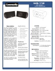
<strong>ENT</strong>ASYS Pan-Tilt Bracket Kit Assembly Instructions1. The <strong>ENT</strong>ASYS T-Bar Mounting Bracket, sometimes referred to as the “T-bracket”, is included and shipped attached to each<strong>ENT</strong>ASYS column loudspeaker. Remove the T-Bar Mounting Brackets from each <strong>ENT</strong>ASYS column to be connected together.This is most easily accomplished by either laying the <strong>ENT</strong>ASYS loudspeaker on its side or placing it upside down on a levelsurface. There are eight set screws, four on each side of the rear of the enclosure, that secure this bracket to the enclosure.Once these are sufficiently loosened, the Mounting Bracket may be slid down parallel to the enclosure, as if pulling it awayfrom the bottom of the enclosure, approximately 3 inches (75 mm). It can then be pulled out of the slot and away from theenclosure.10mm LOCK WASHER10mm FLAT WASHERTOP WALLBRACKETLOCKING BARSlide Mounting Bracket 3” (75 mm)M10 HEX NUTFigure 1: T-Bar Mounting Bracket RemovalM6 HEX NUT (TYP)6mm LOCK WASHER6mm FLATWASHERSMALLEXTENSIONBRACKETMEDIUMEXTENSIONBRACKETPull Mounting Bracket awayfrom loudspeakerFigure 2: Top Assembly DetailM6 HEX NUT (TYP)6mm LOCK WASHER(TYP)6mm FLATWASHER(TYP)TOPANGLEBRACKETLoosen eight SetScrews"T " MOUNTING BRACKET(EXISTING)If multiple columns joined in a tall array are to be mounted usinga single Pan-Tilt Bracket, purchase the <strong>ENT</strong>ASYS Coupler Bracket(part number <strong>ENT</strong>-CB) and follow the instructions in thecomplete <strong>ENT</strong>ASYS Installation/Operation Manual included witheach <strong>ENT</strong>ASYS column loudspeaker.2. For a single loudspeaker array, securely fasten four of theM6 x 30mm bolts and nuts to the “T” Mounting Bracket inthe top four holes of the “T” Mounting Bracket. For amultiple loudspeaker array, securely fasten the four M6 x30mm bolts and nuts to the top four holes in the topCoupler Bracket and “T” Mounting Bracket (Note thatscrews currently in these holes in the Coupler Bracket mustbe removed first). This will yield four mounting studs forthe Top Angle Bracket. Do this before attaching any otherparts of the Pan-Tilt Bracket or the washers to the “T”Mounting Bracket.3. Attach the Top Angle Bracket to the four mounting studsusing the four M6 nuts, lock washers, and flat washers.Tighten these nuts securely.4. Attach the Top Wall Bracket to the Small Extension Bracketusing the M10 x 25mm bolt, flat washer, lock washer, andnut. Be sure to place the Locking Bar into position duringthis step. Only finger tighten the M10 bolt and nut.5. Attach the Medium and Large Extension Brackets to theSmall Extension Bracket as needed to achieve the correctlength for the desired down-tilt angle. Use the M6 x 16mmpan head screws, flat washers, lock washers, and nuts.Tighten securely. The <strong>ENT</strong>ASYS Installation/OperationManual contains informational tables detailing whichExtension Brackets to use for a particular array sizeand down-tilt angle. Use the fewest number of ExtensionBrackets possible to achieve the correct total length. Besure to attach additional Extension Brackets below theprevious Extension Bracket as they progress away from theSmall Extension Bracket.6. Insert the M6 x 25mm screw, flat washer, lock washer, andnut into position in the Locking Bar and Top Wall Bracketand tighten.Figure 3: Bottom Assembly Detail"T" MOUNTING BRACKET(EXISTING)Figure 4: <strong>ENT</strong>ASYS 3-Column Array withPan-Tilt Bracket"T" MOUNTING BRACKET(EXISTING)SEE TOPASSEMBLYDETAILCOUPLER BRACKET(<strong>ENT</strong>-CB)COUPLER BRACKET(<strong>ENT</strong>-CB)10mm FLAT WASHERM10 x 25HEX HEAD SCREWM6 x 25 PHILIPSPAN HEAD SCREW6mm FLATWASHERLARGEEXTENSIONBRACKETM6 x 16PHILIPS PAN HEADSCREW-EXTENSIONBRACKET TO TOPANGLE BRACKETAND TO EACH OTHER(TYP)(4) M6 x 30mmFLAT HEAD SCREWBOTTOMBRACKETBOTTOM FITTING(EXISTING)"T" MOUNTING BRACKET(EXISTING)SEE BOTTOMASSEMBLYDETAIL10mm FLAT WASHER10mm LOCK WASHER(8) M6 HEX NUT(4) 6mm LOCK WASHER(4 ) 6mm FLAT WASHERCOUPLER BRACKET(<strong>ENT</strong>-CB)M10 x 20 HEX HEADMACHINE SCREW