CYLINDER HEAD (4A–FE) - CelicaTech
CYLINDER HEAD (4A–FE) - CelicaTech
CYLINDER HEAD (4A–FE) - CelicaTech
You also want an ePaper? Increase the reach of your titles
YUMPU automatically turns print PDFs into web optimized ePapers that Google loves.
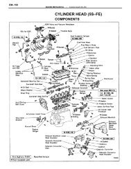
ENGINE MECHANICAL–Cylinder Head (<strong>4A–FE</strong>)EM–8724. REMOVE <strong>CYLINDER</strong> <strong>HEAD</strong> COVERRemove the three cap nuts, grommets, head cover andgasket.25. DISCONNECT TIMING BELT FROM CAMSHAFTTIMING PULLEY(See steps 2 and 4 to 15 on pages EM–33 to 36)NOTICE:• Support the timing belt, so the meshing of thecrankshaft timing pulley and timing belt does notshift.• Be careful not to drop anything inside the timingbelt. cover.• Do not allow the belt to come into contact with oil,water or dust.26. REMOVE CAMSHAFT TIMING PULLEY(See step 16 on page EM–36)27. REMOVE FAN BELT ADJUSTING BARRemove the two bolts and adjusting bar.28. REMOVE ENGINE HANGERSRemove the bolt and engine hanger. Remove the twoengine hangers.29. REMOVE PS DRIVE BELT ADJUSTING STRUTRemove the two bolts and adjusting strut.30. REMOVE CAMSHAFTSNOTICE: Since the thrust clearance of the camshaft issmall, the camshaft must be kept level while it isbeing removed. If the camshaft is not kept level, theportion of the cylinder head receiving the shaft thrustmay crack or be damaged, causing the camshaft toseize or break. To avoid this, the following stepsshould be carried out.A. Remove intake camshaft(a) Set the intake camshaft so the knock pin is slightlyabove the top of the cylinder head.HINT: The above angle allows the No.1 and No.3 cylindercam lobes of the intake camshaft to push their valvelifters evenly.


