CYLINDER HEAD (4A–FE) - CelicaTech
CYLINDER HEAD (4A–FE) - CelicaTech
CYLINDER HEAD (4A–FE) - CelicaTech
You also want an ePaper? Increase the reach of your titles
YUMPU automatically turns print PDFs into web optimized ePapers that Google loves.
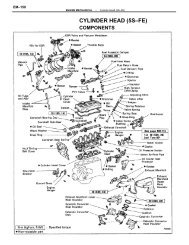
EM–108ENGINE MECHANICAL–Cylinder Head (<strong>4A–FE</strong>)(l) Turn the exhaust camshaft clockwise, and set itwith knock pin facing upward.(m) Check that the timing marks of the camshaftgears are aligned.HINT: The assembly installation marks are on upside.4. CHECK AND ADJUST VALVE CLEARANCE(See page EM–13)Turn the camshaft and position the cam lobe upward,and check and adjust the valve clearance.Valve clearance (Cold):Intake 0.15 – 0.25 mm (0.006 – 0.010 in.)Exhaust 0.20 – 0.30 mm (0.008 – 0.012 in.)5. INSTALL PS DRIVE BELT ADJUSTING STRUTInstall the adjusting strut with the two bolts.Torque: 39 N–m (400 kgf–cm, 29 ft–lbf)6. INSTALL ENGINE HANGERSInstall the engine hanger with the bolt. Install the twoengine hangers.Torque: 27 N–m (280 kgf–cm, 20 ft–lbf)7. INSTALL FAN BELT ADJUSTING BARInstall the adjusting bar with the two bolts.Torque: 20 N–m (200 kgf–cm, 14 ft–lbf)8. INSTALL CAMSHAFT TIMING PULLEY(See step 7 on page EM–41)9. INSTALL TIMING BELT(See steps 8 to 13,15 to 17,19 to 22 on pages EM–41to 45)


