

CYLINDER HEAD (4A–FE) - CelicaTech
CYLINDER HEAD (4A–FE) - CelicaTech
CYLINDER HEAD (4A–FE) - CelicaTech

You also want an ePaper? Increase the reach of your titles
YUMPU automatically turns print PDFs into web optimized ePapers that Google loves.
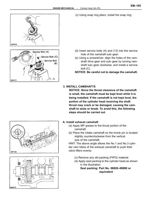
ENGINE MECHANICAL–Cylinder Head (<strong>4A–FE</strong>)EM–105(c) Using snap ring pliers, install the snap ring.(d) Insert service bolts (A) and (13) into the servicehole of the camshaft sub–gear.(e) Using a screwdriver, align the holes of the camshaftdrive gear and sub–gear by turning camshaftsub–gear clockwise, and install a servicebolt (C).NOTICE: Be careful not to damage the camshaft.3. INSTALL CAMSHAFTSNOTICE: Since the thrust clearance of the camshaftis small, the camshaft must be kept level while it isbeing installed. If the camshaft is not kept level, theportion of the cylinder head receiving the shaftthrust may crack or be damaged, causing the camshaftto seize or break. To avoid this, the followingsteps should be carried out.A. Install exhaust camshaft(a) Apply MP grease to the thrust portion of thecamshaft.(b) Place the intake camshaft so the knock pin is locatedslightly counterclockwise from the verticalaxis of the camshaft.HINT: The above angle allows the No.1 and No.3 cylindercam lobes of the exhaust camshaft to push theirvalve lifters evenly.(c) Remove any old packing (FIPG) material.(d) Apply seal packing to the cylinder head as shownin the illustration.Seal packing: Part No. 08826–00080 orequivalent


