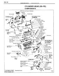
CYLINDER HEAD (4A–FE) - CelicaTech
CYLINDER HEAD (4A–FE) - CelicaTech
CYLINDER HEAD (4A–FE) - CelicaTech
Create successful ePaper yourself
Turn your PDF publications into a flip-book with our unique Google optimized e-Paper software.
EM–100ENGINE MECHANICAL–Cylinder Head (<strong>4A–FE</strong>)(f) Measure the Plastigage at its widest point.Standard oil clearance: 0.035 – 0.072 mm(0.0014 – 0.0028 in.)Maximum oil clearance: 0.10 mm (0.0039 in.)If the oil clearance is greater than maximum, replace thecamshaft. If necessary, replace the bearing caps andcylinder head as a set.(g) Completely remove the Plastigage.G. Inspect camshaft thrust clearance(a) Install the camshafts.(See step 3 on pages EM–105 to 107)(b) Using a dial indicator, measure the thrust clearancewhile moving the camshaft back and forth.Standard thrust clearance:IntakeExhaust0.030 – 0.085 mm(0.0012 – 0.0033 in.)0.035 – 0.090 mm(0.0014 – 0.0035 in.)0.11 mm (0.0043 in.)Maximum thrust clearance:If the thrust clearance is greater than maximum, replacethe camshaft. If necessary, replace the bearing caps andcylinder head as a set.H. Inspect camshaft gear backlash(a) Install the camshafts without installing the exhaustcamshaft sub–gear.(See step 3 on pages EM–105 to 107)(b) Using a dial indicator, measure the backlash.Standard backlash: 0.020 – 0.200 mm(0.0008 – 0.0079 in.)Maximum backlash: 0.30 mm (0.0188 in.)If the backlash is greater than maximum, replace thecamshafts.11. INSPECT VALVE LIFTERS AND LIFTER BORES(a) Using a caliper gauge, measure the lifter bore diameterof the cylinder head.Lifter bore diameter: 28.005 – 28.026 mm(1.1026 –1.1034 in.)


