
You also want an ePaper? Increase the reach of your titles
YUMPU automatically turns print PDFs into web optimized ePapers that Google loves.
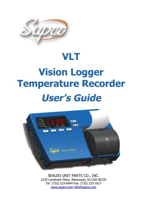
<strong>VLT</strong>Vision LoggerTemperature Recorder<strong>User</strong>’s <strong>Guide</strong>SEALED UNIT PARTS CO., INC.2230 Landmark Place, Allenwood, NJ USA 08720Tel: (732) 223-6644 Fax: (732) 223-1617www.supco.com info@supco.com
Limited Warranty<strong>Supco</strong> International Ltd hereby warrants that it will repair or replace, at its option, any part of the VisionLogger Temperature Recorder or any of its accessories, which proves defective by reason of improperworkmanship or material, free of charge for parts and labor, for a period of ONE YEAR from the date oforiginal purchase by the buyer. This warranty does not apply if, in the sole opinion of <strong>Supco</strong> InternationalLtd, the Vision Logger Temperature Recorder, or any of its accessories, has been intentionally oraccidentally damaged due to misuse, neglect, or improper packing, shipping, modification or servicing,by other than <strong>Supco</strong> International Ltd, or personnel authorized by <strong>Supco</strong> International Ltd. Forinformation on how to obtain service under this warranty, contact the dealer where your Vision LoggerTemperature Recorder was purchased or contact <strong>Supco</strong> International Ltd at the address printed below:SEALED UNIT PARTS CO., INC., P.O. BOX 21, 2230 Landmark Place, Allenwood, NJ, USA 08720Tel: (732) 223-6644, Fax: (732) 223-1617Liability Disclaimer Statement<strong>Supco</strong> makes no warranty, representation, or guarantee regarding the suitability of its products for anyparticular purpose, nor does <strong>Supco</strong> assume any liability arising out of the application or use of anyproduct, and specifically disclaims any and all liability, including without limitation consequential orincidental damages.<strong>Supco</strong> products are not designed, intended, or authorized for use as components in life support systems, orfor any other application in which the failure of the <strong>Supco</strong> product could create a situation where personalinjury or death or significant financial loss may occur.Should any person or persons purchase or use <strong>Supco</strong> products for any such unintended or unauthorizedapplication, that person or persons shall indemnify and hold <strong>Supco</strong> and its officers, employees, affiliates,and distributors harmless against all claims, costs, damages, and expenses, and reasonable attorney feesarising out of, directly or indirectly, any claim of personal injury, death or financial loss associated withsuch unintended or unauthorized use, even if such claim alleges that <strong>Supco</strong> was negligent regarding thedesign or manufacture of the product in question.Installation Instructions and Precautions1. The appliances in the package are designed for wall mounting or table-top installation.2. When mounting the product on a wall, be sure to use the correct type of screw. Secure all screws toprevent the product from falling from its mounting.3. Make all the connections to the product first, and only afterwards mount the transformer on the wall.Safety Precautions1. Install the product in a dry environment. Prevent humid conditions and water leakage.2. Protect the project and power supply from extreme temperatures. Do not install the product nearradiators or in direct sunlight.3. Prevent any foreign objects from falling on the product. Prevent spillage of any liquids, such asstrong acids.4. Connect the power supply to the appropriate voltage, as marked on the unit.5. In order to prevent damage to cables and connectors, do not disconnect cables by pulling on them.6. Route all cables where they will not cause hazard and ensure that the cables are not harmed in anyway.Warnings1. Do not replace cables or connectors with non-original parts.2. Fault connections may cause electrocution.3. The power supply is designed for indoor use only.
TABLE OF CONTENTSChapter 1 Introduction .........................................................1Features..........................................................................................1Description .....................................................................................2Chapter 2Chapter 3Installation.............................................................4Package Contents............................................................................4Installation Options.........................................................................5Bracket Mounting ....................................................................5Connections....................................................................................6Mandatory Connections and Startup.........................................6Optional Connections...............................................................7Viewing Information on an External PC...................................7Power .............................................................................................8Power Source ..........................................................................8Battery Installation and Replacement .......................................9Operation.............................................................10Displaying Temperatures...............................................................10Printing.........................................................................................11Advancing and Changing Printer Paper..........................................11Alarms..........................................................................................12Chapter 4 Configuration ......................................................14Online Help ..................................................................................15Configuring Alarm Settings...........................................................15Configuring the Alarm Range.................................................16Configuring the Alarm Delay .................................................16Vision Recorderi
Configuring the Alarm Output ................................................16Configuring the End of Paper Alarm ......................................17Configuring Print Settings .............................................................18Configuring Temperature and Date Formats...................................19Changing the Time and Date .........................................................20Changing the Password .................................................................20Changing the Device ID................................................................21Changing the Temperature Calibration...........................................22Erasing the Log.............................................................................22Changing the Sampling Rate .........................................................22Chapter 5 Troubleshooting ..................................................23Appendix A Factory Default Settings .....................................24Appendix B Specifications.......................................................26Appendix C Components.........................................................27Appendix D Menu Structure ...................................................28iiVision Recorder
CHAPTER 1I NTRODUCTIONThe Vision Logger Temperature Recorder (<strong>VLT</strong>) records, saves, and prints up to290 temperature readings at predefined intervals. The <strong>VLT</strong> produces an alarmwhenever the temperature goes above or below a defined range. The alarm can beproduced immediately when the temperature goes out of the defined range, or afterthe temperature remains out of range for a certain period of time. The <strong>VLT</strong> providesseveral printing options, including the ability to send data to an external PC. The<strong>VLT</strong> can also send alarms to an external device via a relay contact.The <strong>VLT</strong> can monitor, log, and print temperatures of -40°C to +130°C (-40°F to+266°F), +\- 1°.FEATURESTable 1 describes the <strong>VLT</strong> features, with references to the section and page in thismanual describing how to use or configure the feature.Table 1: Vision Logger Temperature Recorder FeaturesFEATURERecords temperatures at intervals of between one and 90minutesProduces an alarm if the temperature goes above orbelow a predefined rangeRecords and displays temperatures in either Celsius orFahrenheit, and date in European or <strong>English</strong> (American)formatFOR FURTHER INFORMATION SEEChanging the Sampling Rate onpage 22Configuring the Alarm Range onpage 16Configuring Temperature and DateFormats on page 19Records and prints 290 readings on request at any time Printing on page 11Three printing formats, including graphic or text, and IDnumber, time, temperature, and alarm statusAudio and visual alarms, including an option for sendingalarms to an external deviceOption to export data to external PCOptional backup battery for up to 60 hoursConfiguring Print Settings on page 18Alarms on page 12 and OptionalConnections on page 7Viewing Information on an ExternalPC on page 7Battery Installation and Replacementon page 9Vision Recorder 1
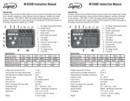
DESCRIPTIONFigure 1 shows the front and top of the <strong>VLT</strong>.Figure 1: Vision Logger Temperature Recorder - Front/Top View1. Power switch2. RS-232 port3. 12V power jack4. Buzzer silent contacts5. Temperature sensor input jack6. Remote alarm contacts7. Paper cover clip8. Secure to the bracket9. Paper cover2 Vision Recorder
Figure 2 shows the rear and bottom of the <strong>VLT</strong>.Figure 2: Vision Logger Temperature Recorder - Rear View10. Secure tie hole11. Hanging hole12. Bracket hanging hole13. Batteries cover14. Bracket mounting15. Buzzer alarm grillFigure 3 shows the display area of the <strong>VLT</strong>.Figure 3: Vision Logger Temperature Recorder - Display AreaVision Recorder 3
CHAPTER 2INSTALLATIONThis chapter explains how to install the <strong>VLT</strong>, and includes the following topics:▲ Package Contents – Lists the contents of the <strong>VLT</strong> package.▲ Installation Options – Describes the possible ways to install the <strong>VLT</strong>, anddescribes how to attach the <strong>VLT</strong> to a wall bracket.▲ Connections – Describes the mandatory and optional cable connections,including instructions on how to start the <strong>VLT</strong>.▲ Power – Describes the <strong>VLT</strong>’s power requirements and backup batteryoperation capability, and explains how to install or replace batteries.PACKAGE CONTENTSThe <strong>VLT</strong> package should include the following components:Table 2: Package ContentsDESCRIPTION QUANTITY PART NUMBER<strong>VLT</strong> unit with one temperature channel 1 <strong>VLT</strong> (115V),<strong>VLT</strong>220 (220V Europe)<strong>VLT</strong>12 (to vehicle)Waterproof, remote 33 feet temperature sensorcord (10 meters)Thermal paper roll, 2 inches wide, 131 feet long(40 meters)12V AC/DC power adaptor - US (120V) OR12V AC/DC power adaptor - EU (230V)# <strong>VLT</strong>12 has DC cord instead of power adaptor1 <strong>VLT</strong>SENSOR2 (1 installed) VLPAPER1 VL115VL220 (Europe)CRCPW3.6V Lithium battery (CR2032) 1 (installed) VLBATHanging bracket 1 VLBRKT<strong>User</strong>’s <strong>Guide</strong> 1 VLMANUALBracket mounting screws 3Bracket securing screw 14 Vision Recorder
INSTALLATION OPTIONSYou can use the <strong>VLT</strong> as a standalone unit or attach it to a wall. There are two waysto attach the <strong>VLT</strong> to a wall:▲ Direct Mounting – Attach the <strong>VLT</strong> directly to the wall.▲ Bracket Mounting – Attach the <strong>VLT</strong> bracket to the wall, and hang the <strong>VLT</strong> onthe bracket, as described below.Bracket MountingTo attach the <strong>VLT</strong> to the wall using the bracket:1. Mount the <strong>VLT</strong> bracket to the wall with three screws, as shown in Figure 4.HooksFigure 4: Bracket MountingNote:Make sure to leave enough space on the left to operate the main switchand connect all the other cables mentioned in Connections on page 6.2. Hang the <strong>VLT</strong> on the two mounted bracket hooks, as shown in Figure 4.3. Open the paper cover by pushing the two cover clips (item 7 in Figure 1) to theinside and pulling the cover out.4. Fasten one screw through the hole under the paper roll to secure the <strong>VLT</strong> to thebracket, as shown in Figure 5.5. Return the paper cover to its place.Vision Recorder 5
Figure 5: Securing the Unit to the BracketCONNECTIONSThis section describes the cables you must connect in order to use the <strong>VLT</strong>, as wellas cables you can attach in order to use optional features.Mandatory Connections and StartupTo connect and start up the <strong>VLT</strong>:1. Plug the AC adaptor into the power supply and connect the 12V power cord tothe power jack (item 3 in Figure 6).2. Connect the temperature sensor cord to the temperature sensor input jack (item 5in Figure 6).3. Switch the power switch to the On position (item 1 in Figure 6). The Power andSensor LEDs turn green. After a few moments, the temperature should appear inthe display area.Figure 6: Connections6 Vision Recorder
Optional ConnectionsYou can connect the following optional cables:▲ To send alarms to a remote device, attach a cable to the remote alarm contacts(item 6 in Figure 6). The remote alarm contacts are a pair of ¼” terminals,1 Amps, 12V.▲ To export temperature data to a PC, attach an RS-232 cable from the PC to theRS-232 port (item 2 in Figure 6).▲ To silence the alarm, connect a remote buzzer silencing device by attaching acable with a momentary switch to momentarily short the buzzer silencercontacts (item 4 in Figure 6). The buzzer silencer contacts are a pair of ¼”terminals.Viewing Information on an External PCBefore you can view information from the <strong>VLT</strong> on an external PC, you mustestablish a new Hyper Terminal connection on the PC.Note:If you have already established a Hyper Terminal connection on your PC,skip to Viewing Information on an External PC on page 8.Establishing a New Hyper Terminal ConnectionTo establish a new Hyper Terminal connection on your PC:1. Connect an RS-232 cable from the PC to the RS-232 port (item 2 in Figure 6).2. On the PC, open Hyper Terminal. To open Hyper Terminal, selectStart>Programs>Accessories>Communications>HyperTerminal anddouble-click HYPERTRM.EXE.Note:If Hyper Terminal is not installed on your computer, you can install itfrom the Control Panel. Double-click Add/Remove Programs, click theWindows Setup tab, select Communications, click Details, selectHyper Terminal, click OK, then click OK again.3. Enter a name for the <strong>VLT</strong> connection.4. Select an icon and click OK.5. In the Connect to window, go to the lower Connect using: menu and selectDirect to Com1 (making sure to choose a free Com port).Vision Recorder 7
6. Click OK. If the Com port is not free, choose another port by selecting File>Properties> and selecting the corresponding COM port, and then click OK.Note:Configure the COM properties as follow: Bits per second - 9600; Databits - 8; Parity - None; Stop bits - 1; Flow control - None,Viewing Information on an External PCTo view information from the <strong>VLT</strong> on an external PC:1. Connect an RS-232 cable from the PC to the RS-232 port (item 2 in Figure 6).2. On the PC, open the <strong>VLT</strong> Hyper Terminal connection program. To open it,select Start> Programs> Accessories> Communications> HyperTerminaland double-click the <strong>VLT</strong> Hyper Terminal icon that you previously created(refer to Establishing a New Hyper Terminal Connection on page 7).The <strong>VLT</strong> Hyper Terminal window on the PC displays message lines according tothe sampling rate. The Hyper Terminal displays whatever information the <strong>VLT</strong>prints, both manually and automatically. For information on printing manually,refer to Printing on page 11. For information on printing automatically, refer toConfiguring Print Settings on page 18.Notes:To capture lines one after the other, select File> Properties and select theSetting tab. Under ASCII Setup, select Append line feed to incomingline ends.To capture the data to a file, select Transfer> Capture Text. Enter thefile name and click Start.When the print format is configured as graph, only the current temperatureand the alarm range appear in Hyper Terminal. On every 12 th row, the datais displayed in full text format.POWERThis section explains the <strong>VLT</strong>’s power requirements and backup battery operationcapability, and explains how to install or replace batteries.Power SourceThe <strong>VLT</strong> uses a 12V AC/DC power supply. When the <strong>VLT</strong> is using the mainpower supply, the Power LED is lit green.8 Vision Recorder
In the event of a power failure, or if the working environment temperature goesover 150°F (65°C), the <strong>VLT</strong> automatically switches over to a 9V backup battery (ifinstalled). When operating in backup mode, the <strong>VLT</strong> logs temperaturemeasurements to memory, but does not print. The Power LED blinks, and thedisplay area shows the current temperature every 30 sec. for two seconds. You canalso display the current temperature for two seconds at a time manually by pressing. With a new 9V battery, the <strong>VLT</strong> can operate in backup mode for 60 hours.When the main power returns, the Power LED goes on without blinking, and theprinter prints the temperature measurements that were recorded but not printedwhen the <strong>VLT</strong> was operating in backup mode.Battery Installation and ReplacementThe <strong>VLT</strong> uses two batteries:▲ Lithium battery (CR2032) – Used for saving logging data and configurationsettings, and for running the real-time clock. After replacing the Lithiumbattery, you should check and reset the <strong>VLT</strong> configuration settings.▲ 9V alkaline backup battery – Used for backup operation (refer to PowerSource on page 8). This battery is optional, and is not included with the <strong>VLT</strong>package. When the Low Batt LED blinks, you should replace the 9V backupbattery.To change or install batteries:1. Push and slide the cover of the battery compartment out, as shown in Figure 7.2. Install the batteries as indicated, according to the polarity marks in the batterycompartment.3. Position the cover over the battery compartment and snap it back into place.Figure 7: Battery Installation and ReplacementVision Recorder 9
CHAPTER 3OPERATIONThis chapter explains how to operate the <strong>VLT</strong>, and includes the following topics:▲ Displaying Temperatures▲ Printing▲ Advancing and Changing Printer Paper▲ AlarmsDISPLAYING TEMPERATURESWhen the <strong>VLT</strong> is on, it displays the current temperature. You can also display themaximum and minimum measured temperatures in the <strong>VLT</strong>’s memory by pressingand . The <strong>VLT</strong>’s memory can store up to 290 readings. The time periodthis covers depends on the sampling rate. For example, if the sampling rate is15 minutes, the <strong>VLT</strong>’s internal memory contains the temperature data from the lastthree days.▲ Press to display the lowest temperature in memory. Press again todisplay the highest temperature in memory, AdJ (for adjusting parameters),and to return to the current temperature. After three seconds, the displayautomatically returns to the current temperature.▲ Press to display AdJ (for adjusting parameters). Press again todisplay the highest temperature in memory, the lowest temperature in memory,and to return to the current temperature. After three seconds, the displayautomatically returns to the current temperature.Note:You can configure the <strong>VLT</strong> to display temperatures in either Celsius orFahrenheit. Refer to Configuring Temperature and Date Formats onpage 19.10 Vision Recorder
PRINTINGThe <strong>VLT</strong> can be configured to print temperatures automatically at defined intervals.For a description of the available print modes and instructions on configuring theprint settings, refer to Configuring Print Settings on page 18.In addition, you can manually print the memory report (a list of all savedmeasurements) on demand, or send the report to a PC to view and save theinformation. To send the memory report to the printer or a PC, press . SEndappears in the display area.▲ To print the memory report, press .▲ To send the memory report to a PC, press .▲ If you do not press either button within three seconds, the display automaticallyreturns to the current temperature.The <strong>VLT</strong> prints or sends the memory report in whichever print mode is currentlyconfigured. If the <strong>VLT</strong> is also configured to print or send measurementsautomatically, then when the printing is finished, the <strong>VLT</strong> prints or sends allmeasurements that were recorded during the on demand memory report printing orsending operation.Every report that is printed or sent on demand begins with the message MEMORYREPORT and ends with the message END OF REPORT. The printed or sent ondemand report displays the measurements in reverse order (i.e., currentmeasurements are displayed before the earlier measurements).To manually stop printing or sending a report on demand, press . The printoutor sent report displays the message MEMORY REPORT STOPPED BY USER.Note:When you send a report to a PC, all data is sent within ten seconds.ADVANCING AND CHANGING PRINTER PAPERThe <strong>VLT</strong> uses thermal printing paper to print temperature readings. This type ofpaper uses heat, rather than ink, to print. The <strong>VLT</strong>’s printer does not print onordinary paper. When ordering replacement paper rolls, make sure to order thermalpaper.Vision Recorder 11
When a red mark appears on the side of the paper, this indicates that the paper rollis almost finished. You should replace the paper roll before it reaches the end, sothat the printer paper will not stop or get stuck.To replace the paper roll:1. Press two or three times to advance the paper.Note: The button does not work unless the printer is set for automaticprinting. Refer to Configuring Print Settings on page 18.2. Tear out the latest printed report.3. Open the paper cover and remove the leftover paper roll. The alarm buzzer willsound, and the Out of Paper LED will blink.4. Straighten the edge of the new paper roll with a scissors.5. Place the new paper roll in the paper compartment, or inside the open papercover, and push the edge of the paper straight through the printer under theprinter’s black rubber roller.6. Press to advance the paper through the printer. After installing the newroll, the alarm buzzer and the Out of Paper LED should go off.ALARMSThe <strong>VLT</strong> has the following alarm indicators:▲ Buzzer – Some alarms trigger an internal buzzer. You can silence the buzzerby pressing or on the optional remote buzzer-silencer switch. Refer toOptional Connections on page 7.You can also configure the <strong>VLT</strong> so that thebuzzer does not go on. Refer to Configuring the Alarm Output on page 16.Note:The buzzer silencer only shuts off the internal buzzer sounds. The alarmLEDs and the external device connected to the relay contact (if enabled)remain operational.▲ LEDs – The four LEDs to the left of the display area indicate various alarms,as described below. The top LED indicates that the <strong>VLT</strong>’s power is on.▲ Relay Contact to External Device – You can connect the external device tothe <strong>VLT</strong> remote alarm contacts (item 6 in Figure 6 on page 6) and configurethe <strong>VLT</strong> to send alarms to the external device via a normally open relaycontact. Refer to Configuring the Alarm Output on page 16.12 Vision Recorder
The following events trigger an alarm:▲ Disconnected Temperature Sensor – If the temperature sensor isdisconnected from the <strong>VLT</strong>, the display area shows the message nOS, theAlarm LED lights, and the internal buzzer sounds (if enabled).▲ Alarm Range – If the measured temperature goes outside the maximum orminimum defined temperature range for a consecutive period of time equal tothe defined alarm delay period (if any), an alarm is sent. The internal buzzersounds (if enabled), and an alarm is sent to an external device via the relaycontact (if enabled). In addition, the Alarm LED lights. For instructions onconfiguring the buzzer and relay contact to respond to Alarm Range alarms,refer to Configuring the Alarm Output on page 16.▲ End of Paper – If the printer paper runs out, the internal buzzer sounds (ifenabled), and an alarm is sent to an external device via the relay contact (ifenabled). In addition, the Out of Paper LED lights. For instructions onconfiguring the buzzer and relay contact to respond to Out of Paper alarms,refer to Configuring the End of Paper Alarm on page 17.Figure 8 provides a close-up of the rear panel, including the remote alarm contactson the right side and the remote buzzer silencing device contacts on the left side.Buzzer silencingcontactsFigure 8: Rear Panel Close-UpRemote alarmcontactsVision Recorder 13
CHAPTER 4CONFIGURATIONThis chapter explains how to configure the <strong>VLT</strong>. To configure <strong>VLT</strong> parameters,you must enter a password. The default password is. Forinstructions on changing your password, refer to Changing the Password onpage 20.To change the <strong>VLT</strong> configuration:1. Press or until AdJ appears in the display area.2. Press . PASS appears in the display area.3. Enter your password. ALr appears in the display area. ALr allows you tochange the alarm settings.4. The <strong>VLT</strong> has nine root menu items. To scroll through the root menu items, press. To scroll through the root menu items in reverse order, press . Thefollowing are the root menu items:∇∇∇∇∇∇∇∇∇ALr – Alarm configurationPrn – Printing configurationSCAL –Temperature units and date format configurationCLoC – Date and time configurationChPA – Change passwordSIdn – ID number configurationCALb – Temperature calibrationLo9r – Erasing the logging measurements from the memorySAPr – Sampling rate configurationNote:For a full diagram of the <strong>VLT</strong> menu tree, refer to Appendix D, MenuStructure on page 28. For a list of the default factory settings, refer toAppendix A, Factory Default Settings on page 24.5. When you reach the root menu item that you want, press . The firstsub-menu item appears.6. When you have finished configuring an item, you must press to save theconfiguration changes.14 Vision Recorder
ONLINE HELPThe <strong>VLT</strong> offers online help that explains the short format display massages andguides you through the menu configurations.1. Open the paper cover to best view the printed online help messages.2. If you want help on any menu item, press . The <strong>VLT</strong> will print and/orsend the online help message in whichever format is currently configured(as described in Configuring Print Settings on page 18).Note: The key can be used to access the online help in all situations, exceptwhile the current temperature is being displayed.3. The <strong>VLT</strong> prints and/or sends a blank line after every online help message.Notes:You cannot print online help unless the printer is set for automaticprinting. Refer to Configuring Print Settings on page 18.If the <strong>VLT</strong> is configured to send output to an external PC, help messageswill also be sent to the external PC.CONFIGURING ALARM SETTINGSTo configure alarm settings, display the ALr root menu. From the ALr root menu,you can configure the following alarm settings:▲ Alarm Range Set (ALS) – Allows you to define a temperature range. Whenthe current temperature is outside of this range, the <strong>VLT</strong> sends an alarm.▲ Alarm Delay (ALdl) – Allows you to define an alarm delay. If the currenttemperature goes out of the defined temperature range, the <strong>VLT</strong> does not sendan alarm until the temperature remains outside of the range for the length oftime defined by the Alarm Delay parameter.▲ Alarm Output (ALO) – Allows you to define whether or not the <strong>VLT</strong>’sinternal alarm sounds when an alarm is sent, and whether or not alarms are sentto an external device.▲ End of Paper Alarm (EOFP) – Allows you to define whether or not the<strong>VLT</strong>’s internal alarm sounds, and whether or not alarms are sent to an externaldevice, when the paper runs out.Vision Recorder 15
Configuring the Alarm RangeTo configure the high and low temperatures that will trigger an alarm:1. From the ALr menu, press . ALS appears.2. Press . LoA1 appears. Press or to set the minimum temperature.Temperatures below this temperature will trigger an alarm.3. Press . HIA1 appears. Press or to set the maximum temperature.Temperatures above this temperature will trigger an alarm.4. Press . The changes are saved and ALS appears.∇ To change other alarm settings, press or to display the otheralarm menu items.∇ To go to another root menu item, press again, then press orto display the other root menu items.∇To exit configuration and display the current temperature, presstwice.Configuring the Alarm DelayTo configure the alarm delay:1. From the ALr menu, press . ALS appears.2. Press . ALdl appears.3. Press . The current alarm delay setting appears.4. Press or to scroll among the possible alarm delay values: n0 (nodelay), 10 (minutes), 30 (minutes), 1 h (1 hour), and 2 h (2 hours). When thevalue you want to select appears, press . ALdl appears.5. Press . The changes are saved and ALr appears.6. Press again to exit configuration and display the current temperature.Configuring the Alarm OutputTo configure the alarm output:1. From the ALr menu, press . ALS appears.2. Press or twice. ALO appears.16 Vision Recorder
3. Press . The current alarm buzzer setting appears:∇∇buOn – The internal buzzer will sound when there is an alarm.buOF – The internal buzzer will not sound when there is an alarm.4. To keep the current setting, press . To change the setting, press orto toggle the setting, then press . The current external Normally Opencontact device setting appears:∇∇CoOn – The external Normally Open contact is closed and a signal issent to the external device when there is an alarm.CoOF – A signal is not sent to the external device when there is analarm.5. To keep the current setting, press . To change the setting, press orto toggle the setting, then press . ALO appears.6. Press . The changes are saved and ALr appears.7. Press again to exit configuration and display the current temperature.Configuring the End of Paper AlarmTo configure the End of Paper alarm output:1. From the ALr menu, press . ALS appears.2. Press . EOFP appears.3. Press . The current End of Paper alarm buzzer setting appears:∇∇buOn – The internal alarm sounds when the printer is out of paper.buOF – The internal alarm does not sound when the printer is out ofpaper.4. To keep the current setting, press . To change the setting, press the orbutton to toggle the setting, then press . The current End of Paperexternal device setting appears:∇∇CoOn – An alarm is sent to the external device when the printer is out ofpaper.CoOF – An alarm is not sent to the external device when the printer isout of paper.5. To keep the current setting, press . To change the setting, press orto toggle the setting, then press . EOFP appears.6. Press . The changes are saved and ALr appears.7. Press again to exit configuration and display the current temperature.Vision Recorder 17
next to any line in which the temperature is outside of the definedtemperature range and the delay time has elapsed. In every 12 th row, fullinformation is printed in small character format.Note:When information is printed to an external PC in graph format, the currenttemperature and the alarm range are printed, but the graph itself is notprinted.2. To keep the current setting, press . To change the setting, press orto toggle the setting, then press . The current printer setting appears:∇∇PrOn – The <strong>VLT</strong> printer prints temperature records automatically at thedefined measurement intervals.PrOF – The <strong>VLT</strong> printer does not print temperature records unless yourequest a printout manually. Refer to Printing on page 11.3. To keep the current setting, press . To change the setting, press orto toggle the setting, then press . The current PC output settingappears:∇∇PCOn – The <strong>VLT</strong> sends temperature records to an external PCautomatically at the defined measurement intervals.PCOF – The <strong>VLT</strong> printer does not send temperature records unless yourequest it to send output manually. Refer to Printing on page 11.4. To keep the current setting, press . To change the setting, press orto toggle the setting, then press . Prn appears.5. Press to save your changes, exit configuration, and display the currenttemperature.CONFIGURING TEMPERATURE AND DATE FORMATSTo configure the format in which the <strong>VLT</strong> displays temperatures (Celsius orFahrenheit) and dates (European or American):1. Display the SCAL root menu.2. From the SCAL menu, press . The current temperature format appears:∇∇F d9 – FahrenheitC d9 – Celsius3. To keep the current setting, press . To change the setting, press orto toggle the setting, then press . The current date format appears:∇∇EndA – <strong>English</strong> (American) date format (mm/dd/yy)EudA – European date format (dd/mm/yy)Vision Recorder 19
4. To keep the current setting, press . To change the setting, press orto toggle the setting, then press . SCAL appears.5. Press to save your changes, exit configuration, and display the currenttemperature.CHANGING THE TIME AND DATETo change the time and date:1. Display the CLoC root menu.2. From the CLoC menu, press . SdAY appears.Note: To keep the current date and change the time, press or to togglethe setting to Shr, then follow the instructions starting at number 4.3. To change the date, press . The current month appears in numerical format(01 = January, 02 = February, etc.). Press or to change the setting,then press . The current day of the month appears. Press or tochange the setting, then press . The last two numbers of the year appears.Press or to change the setting, then press . Shr appears.4. To change the time, press when Shr is displayed. The current hourappears. Press or to change the setting, then press . The currenttime in minutes appears. Press or to change the setting, then press. CLoC appears.5. Press to save your changes, exit configuration, and display the currenttemperature.CHANGING THE PASSWORDTo change the <strong>VLT</strong> password:1. Display the ChPA root menu.2. From the ChPA menu, press . PASS appears.3. Enter a sequence of four keys. PASS appears again.4. Enter the same sequence of four keys to confirm the password. If the secondsequence is the same as the first sequence, ChPA appears. If it is not, PASSappears again, and you must repeat steps three and four.5. Press to save the new password, exit configuration, and display the currenttemperature.20 Vision Recorder
CHANGING THE DEVICE IDThe <strong>VLT</strong> has a device ID that appears in temperature reports. The purpose of thedevice ID is to identify the device producing printouts and reports when printoutsand reports are being collected from more than one device.The device ID consists of 11 alphanumeric characters. You can change eachcharacter individually by entering a numerical code of one or two numbers. Table 3shows the code for setting the device ID.Table 3: Numerical Code for Setting Device IDCHR. CODE CHR. CODE CHR. CODE CHR. CODE CHR. CODE0 0 8 8 F 16 N 24 V 321 1 9 9 G 17 O 25 W 332 2 10 H 18 P 26 X 343 3 A 11 I 19 Q 27 Y 354 4 B 12 J 20 R 28 Z 365 5 C 13 K 21 S 29 - 376 6 D 14 L 22 T 307 7 E 15 M 23 U 31To change the device ID:1. Display the SIdn root menu.2. Press . The number 1 appears, followed by a space and a code for the firstID character that will appear in the device. Press or to change thecharacter, according to the code in Table 3.3. Press to move on to the next character. Repeat this procedure for eachcharacter.4. When you are finished, press to save your changes. SIdn appears.5. Press again to exit configuration and display the current temperature.Vision Recorder 21
CHANGING THE TEMPERATURE CALIBRATIONTo change the temperature calibration:1. Display the CALb root menu.2. Press . The number 0.0 appears.3. Press or to raise or lower the temperature measurement, in steps of0.1°. You can raise or lower the measurement by -2° to 2° in one action.4. When you are finished, press . CALb appears.5. Press to save your changes, exit configuration, and display the currenttemperature.ERASING THE LOGThe <strong>VLT</strong> saves the last temperature measurements (up to 290 logs). To erase thelog:1. Display the Lo9r root menu.2. Press . The log is erased, and ALr appears.3. The <strong>VLT</strong> will print and or send the message MEMORY RESET BY USER,, < time> in the currently configured print format.4. Press to exit configuration and display the current temperature.CHANGING THE SAMPLING RATEThe <strong>VLT</strong> measures temperatures at defined intervals. To change the intervals atwhich temperatures are measured:1. Display the SAPr root menu.2. Press . The current sampling rate appears. The sampling rate can be anyvalue between 1 and 90 minutes.3. Press or to change the sampling rate. When you are finished, press. SAPr appears.4. Press to save your changes, exit configuration, and display the currenttemperature.22 Vision Recorder
CHAPTER 5TROUBLESHOOTINGTable 4 lists common problems and suggested solutions.Table 4: TroubleshootingPROBLEMSUGGESTED SOLUTIONSNo powerPoor or no printingWrong time or dateWait five seconds after switching on the power switch.• Make sure you are using thermal printing paper. The <strong>VLT</strong>will not print on non-thermal paper.• Replace the printing side of the thermal paper, or replace thethermal paper itself.• Move the <strong>VLT</strong> to a location with a temperature between 0 to149°F (-18 to 65°C).• Change the time or date. Refer to Changing the Time andDate on page 23.• Make sure you are using the correct date format (dd/mm/yy ormm/dd/yy). Refer to Configuring Temperature and DateFormats on page 19.• Replace the Lithium battery (CR2032). Refer to BatteryInstallation and Replacement on page 9.Cannot print online help Change the print mode to PrOn. Refer to Printing on page 11.Vision Recorder 23
APPENDIX A FACTORY DEFAULT SETTINGSTo restore the Vision Recorder to its factory default settings:1. Switch the power switch off.2. Switch the power switch back on while pressing .3. When FAdF appears in the display area, press .Note:Restoring factory settings does not delete the temperature logs.Table 5 lists the factory default settings.Table 5: Factory Default SettingsMENU ITEM PARAMETER DEFAULTS LEGAL VALUESPASSWORD SETTINGSPASSPasswordALARM SETTINGS (AL.)ALS Alarm Range Settings Min: -4°F (-20°C)Max: 86°F (30°C)-67°F to 302°F(-55°C to 150°C)ALdl Alarm Delay No No, 15, 30 min, 1, 2 hrALO Alarm Output BuOn (buzzer On)CoOn (contact On)EOP End of Paper BuOn (buzzer On)CoOn (contact On)buOn/buOFCoOn/CoOFbuOn/buOFCoOn/CoOFPRINT SETTINGS (PRN)Print Format SChr (small character) LChr (large), SChr(small), 9rAP (graph)Printer On/Off PrOn (Printer On) PrOn, PrOFPC Output On/Off PCOn (PC Output On) PCOn, PCOF24 Vision Recorder
MENU ITEM PARAMETER DEFAULTS LEGAL VALUESTEMPERATURE AND DATE FORMATS (SCAL)# <strong>VLT</strong> # <strong>VLT</strong>220TemperatureFormatF d9(Fahrenheit)C d9 (Celsius)C d9 (Celsius),F d9 (Fahrenheit)Date FormatEndA, <strong>English</strong>,(mm/dd/yy)EudA, Europe,(dd/mm/yy)EudA (dd/mm/yy),EndA (mm/dd/yy)CURRENT DATE AND TIME (CLOC)# <strong>VLT</strong> # <strong>VLT</strong>220SdAY Date 12/31/04 31/12/04Shr Time 12:00 12:00DEVICE ID NUMBER (SIDN)SIdn Device ID Number SUPCO 12345TEMPERATURE CALIBRATION (CALB)CALbTemperatureCalibration0° –2° to 2°SAMPLING RATE (SAPR)SAPr Sampling Rate 10 min 1 to 90 minutesVision Recorder 25
APPENDIX BSPECIFICATIONSTable 6 lists the <strong>VLT</strong>’s specifications.Table 6: SpecificationsDESCRIPTIONTemperature Measurement RangeTemperature Measurement AccuracyAmbient Operating Temperature RangeAmbient Operating Relative HumidityTemperature Writing and Storage ResolutionStorage Temperature RangeSPECIFICATION-40°F to +266°F (-40°C to +130°C)+/- 1.8°F (+/- 1°C)0°F to +150°F (-18°C to +65°C) non-condensing0 to 95% non-condensing0.2°F (0.1°C)-40°F to +150°F (-40°C to +65°C)Temperature Sensor Cord Length (extensible) 33 feet (10 m)Temperature Sensor DiameterAlarm Contact Rating0.25 inches (6.35 mm)1 Amps, 12V AC/DCThermal Chart Paper Width2 inches (50.8 cm)Thermal Chart Paper Length 131 feet (40 m)DisplayPrimary Power SupplyAlternative Power SupplyBattery BackupClock BatterySizeNumeric LED Display, 4 charactersVL115: 115 V AC, 50/60 HzVL220: 220~240V AC, 50/60 Hz12V AC/DC, 1.5 Amps (for vehicle operationwith adapter, not supplied)9V battery, logs up to 50 hours (not supplied)3.6V Lithium battery, two years in average use(supplied)8.2 x 5.3 x 2.7 inches (208.6 x 135 x 69 mm)26 Vision Recorder
APPENDIX CCOMPONENTSTable 7 lists the <strong>VLT</strong>’s components, including optional components.Table 7: ComponentsDESCRIPTION SUPPLIED PART NUMBER<strong>VLT</strong> with temperature channel 1Temperature Sensor, 33 feet (10 m) 1 <strong>VLT</strong>SENSOR2” thermal paper roll, 131 feet length (40 m) 2 VLPAPER12V AC/DC, power adaptor: USA: 130V AC operationEurope: 230V AC operation1 VL115VL2303.6V Lithium battery 1 VLBAT<strong>User</strong>’s Manual 1 VLMANUALWall mounting bracket 1 VLBRKTPaper compartment cover Optional VLPACOBattery compartment cover Optional VLBACOIP65 clear case and hinge, 9.8x9.8x4” (25x25x10cm) Optional VLWPCASESilencer remote kit, 16.4 feet (5m) Optional VLSKExtension cable for temperature sensor, 10 feet (3m) Optional CABLE10HExtension cable for temperature sensor, 33 feet (10m) Optional CABLE33HRS-232 serial data cable, 6 feet (1.8m) Optional RSCABLEVehicle power reducer from 24V DC to 12V DC Optional VPRAutomatic telephone dialerOptional115VOptional230VADTAADTA220Remote Alarm Optional RA25DC power Cord (for vehicle Operation) Optional CRCPWVision Recorder 27
APPENDIX DMENU STRUCTURE28 Vision Recorder