FAK-1: Split Bulkhead Entry Kit for Tubing Bundles
FAK-1: Split Bulkhead Entry Kit for Tubing Bundles
FAK-1: Split Bulkhead Entry Kit for Tubing Bundles

Create successful ePaper yourself
Turn your PDF publications into a flip-book with our unique Google optimized e-Paper software.
<strong>FAK</strong>-1: <strong>Split</strong> <strong>Bulkhead</strong> <strong>Entry</strong> <strong>Kit</strong><strong>for</strong> <strong>Tubing</strong> <strong>Bundles</strong>INSTALLATION PROCEDURES
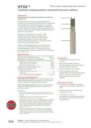
<strong>FAK</strong>-1: <strong>Split</strong> <strong>Bulkhead</strong> <strong>Entry</strong> <strong>Kit</strong>The following installation procedures are suggested guidelines <strong>for</strong>the installation of the <strong>FAK</strong>-1:Receiving, Storing and Handling . . .1. Inspect materials <strong>for</strong> damage incurred during shipping.2. Report damages to the carrier <strong>for</strong> settlement.3. Identify parts against the packing list to ensure the propertype and quantity has been received.4. Store in dry location.Dimensions . . .7-1/2”1-3/4”3”<strong>FAK</strong>-1: <strong>Split</strong> <strong>Bulkhead</strong> <strong>Entry</strong> <strong>Kit</strong> . . .5-1/4”5-1/4”1256834If Electrically Heat Traced• To minimize the potential <strong>for</strong> arcing on electric heat tracing andfi re caused by product damage or improper installation useground-fault protection, the National Electrical Code (NEC) andCanadian Electrical Code (CEC) require ground-fault protection ofequipment <strong>for</strong> each branch circuit supplying electric heat tracing.• Installation must comply with Thermon requirements and beinstalled in accordance with applicable national and local codes.• Component approvals and per<strong>for</strong>mance ratings are based onthe use of Thermon specifi ed parts only. User supplied powerconnection fi ttings must be listed or certifi ed <strong>for</strong> intended use.• De-energize all power sources be<strong>for</strong>e opening enclosure.• Keep ends of bundles, heat tracing and kit components dry be<strong>for</strong>eand during installation.7<strong>FAK</strong>-1: <strong>Bulkhead</strong> <strong>Kit</strong> Contents . . .• Individuals installing these products are responsible <strong>for</strong>complying with all applicable safety and health guidelines.Proper personal protective equipment, or PPE, should beutilized during installation. Contact Thermon if you have anyadditional questions.Item Quantity Description1 1 <strong>Bulkhead</strong> <strong>Entry</strong> Cover (Top)2 1 <strong>Bulkhead</strong> <strong>Entry</strong> Cover (Bottom)3 4 Pan-Head S.S. Screws, #10-32 x .754 4 Kept S.S. Nuts, #10-325 1 Heat Refl ective Tape6 1 Glass Fiber Tape7 3 RTV Sealant Tube8 1 U-Bolt, Washers and NutsTools Required . . .HacksawScrewdriverPliers1
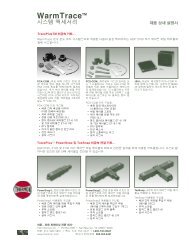
INSTALLATION PROCEDURES<strong>Tubing</strong> BundleInsulationInsulation<strong>Tubing</strong>Heat Trace(if Included)Cut as RequiredBussConnection<strong>Tubing</strong>Heat TracingSelf-Regulating Heat Tracing305mm -381mm(12” - 15”)<strong>Tubing</strong>Bus ConnectionIndentations(Zone Heater Only)Zone Type Heat Tracing305mm -381mm(12” - 15”)1. Strip back bundle insulation 38mm (1-1/2”) to76mm (3”) beyond bus connection heat tracing.If bus connection indentation is less than 305mm(12”)-381mm (15”) from end of the heat tracing,proceed stripping the bundle insulation to the nextindentation.2. Trim heat tracing to within 305mm - 381mm (12”- 15”) of the end of the insulation. If self regulatingheat trace proceed to step 3. For Zone-type heat tracecontinue with indentification of bus connection onstep 2a.2a. Strip back bundle insulation 38mm (1 1/2”) to76mm(3”) beyond bus connection heat tracing.If bus connection indentation is less than 305mm(12”)-381mm (15”) from end of the heat tracing,proceed stripping the bundle insulation to the nextindentation.<strong>FAK</strong>-1Top CoverRTVSealant10-32x .75 PanHead Screws<strong>FAK</strong>-1Bottom Cover<strong>FAK</strong>-1Top Cover10-32 KeptNuts<strong>FAK</strong>-1Bottom Cover3. Form a gasket by applying RTV sealant to bottomhalf of <strong>Bulkhead</strong> <strong>Entry</strong> cover and along radius ofupper half.4. Fit tubing bundle to bottom half of cover and installtop half. Screw down fi rmly.5. Inspect ends of tubing cover <strong>for</strong> snug fi t. Applyadditional RTV sealant where needed.Drilled hole<strong>for</strong> bundleentryDrilled holes<strong>for</strong> U-Boltentry3/16” holes <strong>for</strong>securing <strong>FAK</strong>-1to bulkhead(Field Drilled)6. Drill hole matching bundle diameter into bulkhead.Mark location <strong>for</strong> U-Bolt entry and drill 1/4”(7mm) holes through bulkhead.7. Pre-drill <strong>FAK</strong>-1 with 3/16” (5mm) holes <strong>for</strong>securing <strong>FAK</strong>-1 to bulkhead.RTV Sealant8. Apply RTV bead to back of <strong>FAK</strong>-1 fl ange prior tosecuring to bulkhead.2
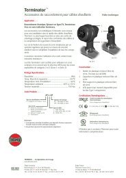
<strong>FAK</strong>-1: <strong>Split</strong> <strong>Bulkhead</strong> <strong>Entry</strong> <strong>Kit</strong>Stainless Steel Screws(Customer Supplied)U-BoltRTV beadBackside View9. Secure <strong>FAK</strong>-1 to bulkhead using (3) threestainless steel screws (customer supplied) andU-Bolt as shown. Complete tubing and heat traceconnections or termination.10. Apply RTV bead around <strong>FAK</strong>-1 fl ange. Completed<strong>FAK</strong>-1 kit.THERMON . . . The Heat Tracing Specialists ®100 Thermon Dr. • PO Box 609 • San Marcos, TX 78667-0609Phone: 512-396-5801 • Facsimile: 512-396-36271-800-820-HEAT • In Canada call 1-800-563-8461For the Thermon offi ce nearest youvisit us at . . .www.thermon.comSpecifi cations and in<strong>for</strong>mation are subject to change without notice. Form PN50048-1012