M-FIAM9 Military COTS 28 Vin Filter Data Sheet
M-FIAM9 Military COTS 28 Vin Filter Data Sheet
M-FIAM9 Military COTS 28 Vin Filter Data Sheet

You also want an ePaper? Increase the reach of your titles
YUMPU automatically turns print PDFs into web optimized ePapers that Google loves.
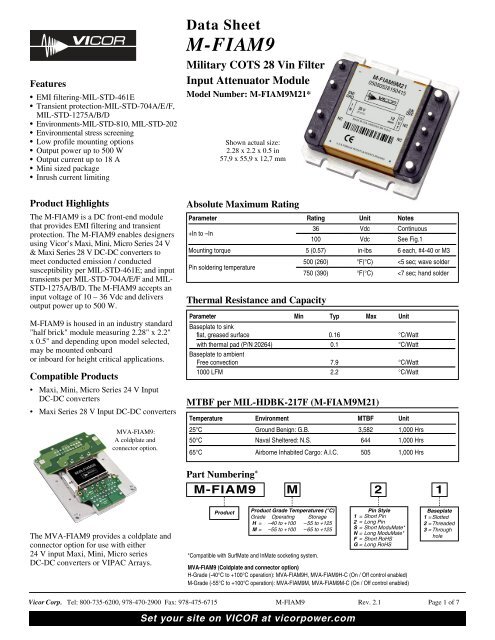
Features• EMI filtering-MIL-STD-461E• Transient protection-MIL-STD-704A/E/F,MIL-STD-1275A/B/D• Environments-MIL-STD-810, MIL-STD- 202• Environmental stress screening• Low profile mounting options• Output power up to 500 W• Output current up to 18 A• Mini sized package• Inrush current limiting<strong>Data</strong> <strong>Sheet</strong>M-<strong>FIAM9</strong><strong>Military</strong> <strong>COTS</strong> <strong>28</strong> <strong>Vin</strong> <strong>Filter</strong>Input Attenuator ModuleModel Number: M-<strong>FIAM9</strong>M21*Shown actual size:2.<strong>28</strong> x 2.2 x 0.5 in57,9 x 55,9 x 12,7 mmProduct HighlightsThe M-<strong>FIAM9</strong> is a DC front-end modulethat provides EMI filtering and transientprotection. The M-<strong>FIAM9</strong> enables designersusing Vicor’s Maxi, Mini, Micro Series 24 V& Maxi Series <strong>28</strong> V DC-DC converters tomeet conducted emission / conductedsusceptibility per MIL-STD-461E; and inputtransients per MIL-STD-704A/E/F and MIL-STD-1275A/B/D. The M-<strong>FIAM9</strong> accepts aninput voltage of 10 – 36 Vdc and deliversoutput power up to 500 W.M-<strong>FIAM9</strong> is housed in an industry standard"half brick" module measuring 2.<strong>28</strong>" x 2.2"x 0.5" and depending upon model selected,may be mounted onboardor inboard for height critical applications.Compatible Products• Maxi, Mini, Micro Series 24 V InputDC-DC converters• Maxi Series <strong>28</strong> V Input DC-DC convertersMVA-<strong>FIAM9</strong>:A coldplate andconnector option.Absolute Maximum RatingParameter Rating Unit Notes+In to –InThermal Resistance and Capacity36 Vdc Continuous100 Vdc See Fig.1Mounting torque 5 (0.57) in-lbs 6 each, #4-40 or M3Pin soldering temperature500 (260) °F(°C)
SPECIFICATIONS(typical at T BP = 25°C, nominal line and 75% load, unless otherwise specified)INPUT SPECIFICATIONSParameter Min Typ Max Unit NotesInput voltage 10 <strong>28</strong> 36 Vdc ContinuousInrush limiting 0.007 A/µFTransient immunity 100 Vdc 50 ms per MIL-STD-1275A/B/D, continuous operation250 Vdc 70 µs per MIL-STD-1275A/B/D, continuous operation70 Vdc 20 ms per MIL-STD-704A, continuous operation50 Vdc 12.5 ms per MIL-STD-704E/F, continuous operationOUTPUT SPECIFICATIONSParameter Min Typ Max Unit NotesOutput power 500 WOutput current 18 AEfficiency 96 97 %Internal voltage drop 0.85 1.5 V 500 W, 25°C baseplateExternal capacitance See Figure 4 on page 4330 1000 µF 50 VCONTROL PIN SPECIFICATIONSParameter Min Typ Max Unit NotesON/OFF controlEnable (ON) 0.0 1.0 Vdc Referenced to – VoutDisable (OFF) 3.5 5.0 Vdc 100 kΩ internal pull up resistorSAFETY SPECIFICATIONSParameter Min Typ Max Unit NotesDielectric withstand1,500 Vrms Input/Output to Base2,121 Vdc Input/Output to BaseEMIStandard Test Procedure NotesMIL-STD-461EConducted emissions:Conducted susceptibility:CE101, CE102CS101, CS114, CS115, CS116When using with V<strong>28</strong> series converters a 27 µH inductor isneeded between the filter and converter for compliancebelow 30% of rated power.GENERAL SPECIFICATIONSParameter Min Typ Max Unit NotesWeight 3.3 (94) Ounces (grams)Warranty 2 YearsVicor Corp. Tel: 800-735-6200, 978-470-2900 Fax: 978-475-6715 M-<strong>FIAM9</strong> Rev. 2.1 Page 2 of 7Set your site on VICOR at vicorpower.com
SPECIFICATIONS (CONT.)ENVIRONMENTAL QUALIFICATIONAltitudeMIL-STD-810F, Method 500.4, Procedure I & II, 40,000 ft. and 70,000 ft. Operational.Explosive AtmosphereMIL-STD-810F, Method 511.4, Procedure I, Operational.VibrationMIL-STD-810F, Method 514.5, Procedure I, Category 14, Sine and Random vibration per Table 514.5C for Helicopter AH-6J Main Rotorwith overall level of 5.6 G rms for 4 hours per axis. MIL-STD-810F, Method 514.5C, General Minimum Integrity Curve per Figure 514.5C-17with overall level of 7.7 G rms for 1 hour per axis.ShockMIL-STD-810F, Method 516.5, Procedure I, Functional Shock, 40 g. MIL-S-901D, Lightweight Hammer Shock, 3 impacts / axis, 1,3,5 ft.MIL-STD-202F, Method 213B, 60 g, 9 ms half sine. MIL-STD-202F, Method 213B, 75 g, 11ms Saw Tooth Shock.AccelerationMIL-STD-810F, Method 513.5, Procedure II, table 513.5-II, Operational, 2-7 g, 6 directions.HumidityMIL-STD-810F, Method 507.4.Solder TestMIL-STD-202G, Method 208H, 8 hour aging.ENVIRONMENTAL STRESS SCREENINGParameter H-Grade M-GradeOperating temperature -40°C to +100°C -55°C to +100°CStorage temperature -55°C to +125°C -65°C to +125°CTemperature cycling*12 cycles 12 cycles-65°C to +100°C-65°C to +100°CAmbient test @ 25°C Yes YesPower cycling burn-in 12 hours, 29 cycles 24 hours, 58 cyclesFunctional and parametric ATE tests -40°C and +100°C -55°C and +100°CHi-Pot test Yes YesVisual inspection Yes YesTest data vicorpower.com vicorpower.com*Temperature cycled with power off, 17°C per minute rate of change.Vicor Corp. Tel: 800-735-6200, 978-470-2900 Fax: 978-475-6715 M-<strong>FIAM9</strong> Rev. 2.1 Page 3 of 7Set your site on VICOR at vicorpower.com
Figure 1 — Transient Immunity: M-<strong>FIAM9</strong> output responseto an input transient.Figure 2 — Conducted Noise; M-<strong>FIAM9</strong> and ModelV<strong>28</strong>A12M200B DC-DC converter operating at <strong>28</strong> Vdc, 200 W.Time (ms)200018001600140012001000800600400200040 50 60 70 80 90 100<strong>Vin</strong> (V)Figure 3 — Shut down time of M-<strong>FIAM9</strong> vs. OvervoltageGain (dB)40200-20-40-60-80-1000.01 0.1 1 10Frequency (MHz)CM Insertion LossDM Insertion LossFigure 4 — M-<strong>FIAM9</strong> insertion lossNote: The M-<strong>FIAM9</strong> is shown in the on state. To disable,open the connection between ON/OFF and –Out.4,700 pF0.01 µF+IN+OUT+IN+OUTF1InputTransorb P/N19180-510NCEMIGND–INNCM-<strong>FIAM9</strong> NCONOFF–OUTC10.2 µFPCPR–INMaxi, Mini, Micro24 Vdc InputDC-DC Converter+SSC–S–OUTComponent SuggestionsRecommended Fuse: (F1) 20 A (max), Bussmann ABC styleCapacitance: (C1) 330 µF (min), 1000 µF (max)4,700 pF0.01 µFFigure 5— Transient, Surge Protection and Recommended Reverse Polarity Protection.Vicor Corp. Tel: 800-735-6200, 978-470-2900 Fax: 978-475-6715 M-<strong>FIAM9</strong> Rev. 2.1 Page 4 of 7Set your site on VICOR at vicorpower.com
MECHANICAL DRAWINGSModule PinsNo. Function Label1 +In +2NoConnectionNC3 Ground EMI/GND4 –In –5 –Out –6 ON/OFF ON/OFF7NoConnectionNC8NoConnectionNC9 +Out +Figure 6 — Mechanical diagramINBOARDSOLDERMOUNTONBOARDSOLDERMOUNT0.062 ±0.010PCB THICKNESS1,57 ±0,25PLATEDTHROUGH HOLE1.790**DIA0.0645,47R (4X) 0.1581,54,01SHORT PIN STYLE(7X)0.094 ±0.0032,39 ±0,08(2X)0.164 ±0.0034,16 ±0,08LONG PIN STYLE0.094 ±0.0032,39 ±0,080.164 ±0.0034,16 ±0,08ALL MARKINGSTHIS SURFACE1 2 3 41.900*48.26 48,26987651.575**40,00ALUMINUMBASEPLATEPINS STYLESSOLDER:TIN / LEADHOT SOLDER DIPPEDMODUMATE: GOLD PLATED COPPERRoHS: GOLD PLATED COPPER0.400*10,160.700*17,780.4310,90.5313,50.1954,951.000*25,401.400*35,56±0.003* DENOTES TOL =±0,08** PCB WINDOWFigure 7 — PCB Mounting Specifications.Vicor Corp. Tel: 800-735-6200, 978-470-2900 Fax: 978-475-6715 M-<strong>FIAM9</strong> Rev. 2.1 Page 5 of 7Set your site on VICOR at vicorpower.com
INCHESMM1.0426,41.5439,1Output Connector0.317,84.7119,4MVA – <strong>FIAM9</strong>Input Connector0.8120,61111020110918Input ConnectorPin #Function1 – 4 –<strong>Vin</strong>5 – 7 +<strong>Vin</strong>8 NC9 PE protective earth10 PE protective earth11 – 13 –<strong>Vin</strong>14 – 17 +<strong>Vin</strong>18 NC19 PE protective earth20 PE protective earthOutput ConnectorPin # Function Pin # Function1 +Vout 10 +Vout2 +Vout 11 +Vout3 +Vout 12 +Vout4 N/C 13 NC5 N/C 14 NC6 N/C 15 On / Off7 –Vout 16 –Vout8 –Vout 17 –Vout9 –Vout 18 –VoutInput Mounting Vicor P/NConnectorHousing 24795Pin 24796Kit 248<strong>28</strong>Output MountingVicor P/NConnectorHousing 25050Pin 24796Kit 25067Note: The MVA-<strong>FIAM9</strong>H and MVA-<strong>FIAM9</strong>M are delivered with the On / Off control already configured as On using a 0 Ohm resistor on theunderside of the output connector board. The MVA-<strong>FIAM9</strong>H-C and MVA-<strong>FIAM9</strong>M-C are delivered without the 0 Ohm resistor installed,allowing for user control of the On / Off functionality .Figure 8 — MVA-<strong>FIAM9</strong> Pakaging OptionVicor Corp. Tel: 800-735-6200, 978-470-2900 Fax: 978-475-6715 M-<strong>FIAM9</strong> Rev. 2.1 Page 6 of 7Set your site on VICOR at vicorpower.com
WarrantyVicor products are guaranteed for two years from date of shipment against defects in material or workmanship when in normaluse and service. This warranty does not extend to products subjected to misuse, accident, or improper application ormaintenance. Vicor shall not be liable for collateral or consequential damage. This warranty is extended to the originalpurchaser only.EXCEPT FOR THE FOREGOING EXPRESS WARRANTY, VICOR MAKES NO WARRANTY, EXPRESS OR IMPLIED,INCLUDING, BUT NOT LIMITED TO, THE WARRANTY OF MERCHANTABILITY OR FITNESS FOR APARTICULAR PURPOSE.Vicor will repair or replace defective products in accordance with its own best judgement. For service under this warranty, thebuyer must contact Vicor to obtain a Return Material Authorization (RMA) number and shipping instructions. Productsreturned without prior authorization will be returned to the buyer. The buyer will pay all charges incurred in returning theproduct to the factory. Vicor will pay all reshipment charges if the product was defective within the terms of this warranty.Information published by Vicor has been carefully checked and is believed to be accurate; however, no responsibility isassumed for inaccuracies. Vicor reserves the right to make changes to any products without further notice to improve reliability,function, or design. Vicor does not assume any liability arising out of the application or use of any product or circuit; neitherdoes it convey any license under its patent rights nor the rights of others. Vicor general policy does not recommend the use ofits components in life support applications wherein a failure or malfunction may directly threaten life or injury. Per VicorTerms and Conditions of Sale, the user of Vicor components in life support applications assumes all risks of such use andindemnifies Vicor against all damages.Vicor’s comprehensive line of power solutions includes high density AC-DC and DC-DCmodules and accessory components, fully configurable AC-DC and DC-DC power supplies,and complete custom power systems.Information furnished by Vicor is believed to be accurate and reliable. However, no responsibility is assumed by Vicor for itsuse. Vicor components are not designed to be used in applications, such as life support systems, wherein a failure ormalfunction could result in injury or death. All sales are subject to Vicor’s Terms and Conditions of Sale, which are availableupon request.Specifications are subject to change without notice.Intellectual Property NoticeVicor and its subsidiaries own Intellectual Property (including issued U.S. and Foreign Patents and pending patentapplications) relating to the products described in this data sheet. Interested parties should contact Vicor's IntellectualProperty Department.Vicor Corporation25 Frontage RoadAndover, MA, USA 01810Tel: 800-735-6200Fax: 978-475-6715emailCustomer Service: custserv@vicorpower.comTechnical Support: apps@vicorpower.comVicor Corp. Tel: 800-735-6200, 978-470-2900 Fax: 978-475-6715 M-<strong>FIAM9</strong> Rev. 2.1 7/09Set your site on VICOR at vicorpower.com