1 - Seldén Mast
1 - Seldén Mast
1 - Seldén Mast

Create successful ePaper yourself
Turn your PDF publications into a flip-book with our unique Google optimized e-Paper software.
2Retro-fitting cablesIdentify the section type of your mast by using the tables below. See also next page. It is quite easy to check thedesign of the after section by removing the headbox. (See page2).”E”sections10° 10°10°(See nextpage for ”D”,”P” and furlingsections.A3)B- 10° plough-shapedafter face- Separate conduits- 10° plough-shaped - 10° plough-shapedafter faceafter face- Separate conduits - Track for plastic conduits- Track for plastic conduits - Double marking lines- Rounded after face.(Excluding section122/85)INSTRUCTION 1A INSTRUCTION 1B INSTRUCTION 2 INSTRUCTION 3A/B Available cable space 1) Available cable space 1) Available cable space 1) Available cable space 1)122/85 -No conduit 2)2 (13x15)130/93 2 (15x15) mm --138/95 2 (15x15) No conduit 2)155/104 2 (15x15)-224/150 2 ▭ (15x16)(plastic conduit) 4) 6)170/155 2 (15x18)2 ▭ (15x16)2) 6)2 ▭ (9x12)177/124 2 ▭ (15x20)+-6)189/132 2 ▭ (15x16)206/139 2 ▭ (15x16)15x506)237/162 2 ▭ (15x17)6)274/185 - - 2) 6)2 ▭ (9x12)321/171See sep. instruction365/195- -595-691-... supplied upon-request.126/852 ▭ (10x12)147/95 2 ▭ (10x12)162/104 2 (15x15)- - -178/115 2 (15x18)216/139 2 (15x20)239/162 2 (17x25)1. “2 (cxd) mm” = two triangular spaces. c d“2 ▭ (cxd) mm” = two rectangular spaces. c d2.3.4.2 off maximum. Ø 9 mm cables can be glued to the sail track.ALT: cable tubing 512-118-01 Ø 35x32 (L=5000)Plastic conduit: 535-608-01 (L=6000 mm)c▭cdd5.6.Plastic conduit: 535-643-01 (L=6000 mm)Also 2(l)x plastic conduit 535-607-01 16x52 (L=6000)
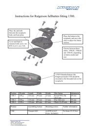
A messenger and a long hook will facilitate passing the goose-neck fitting and track gate. Track gates that arescrewed in place are easily removed. The aforementioned eye on the cable end facilitates threading the cable throughthe hole at the mast-head. To avoid the weight of the cable from being suspended from the point of masthead exit, and to prevent the cable from slamming inside the conduit, the cable must be wedged in place. Thisis best done by forcing pads of closed cell plastic foam at regular intervals along the conduit lenght. Their sizeis dependant upon the space occupied by the cable(s) in the conduit. Try first with 20x20x20 mm pads, fittingthem as shown in figs. l.A.5A to C. It can be a little tricky at first, but one soon gets the knack of it. A pad every60 cm (2’) gives satisfactory support. The advantage of pads over gluing is that the pads are easily removed ifone wants to remove the cable at a later date. (See the last paragraph on this page).5CablePadHook-shaped plate strip.Jaw length appr. 10 mm.Fig. 1.A.5a Fig. 1.A.5b Fig. 1.A.5cKeel stepped mastsOn keel stepped masts the sailtrack and conduits are sealed with silicone rubber on a level with the upper edgeof the mast coat. An exception are those masts that have been left unsealed on customer request, and these areclearly labelled ”OPEN CONDUITS”. (See instruction 595-548-E, not attached). This packing must be removedto give free passage for the cable * and be replaced after the cable has been installed. There are holes wherethe sealant can be injected to re-seal the conduits just above or just below the top edge of the coat.If existing cables are glued, no further steps need be taken. If they are held in place with pads the pads mustfirst be removed before fitting the new cable. Remove the headbox (fig. l.A.2). Insert a hook-shaped plate strip(fig. l.A.5b) below one pad at a time, push the pad to the top end of the mast, and remove it. The track gate canalso be removed, and pads pushed there for removal.These pads can later be re-used for holding both the old and the new cables.*) This is a time-consuming task, so contact <strong>Seldén</strong><strong>Mast</strong> for advice. The method shown opposite can beused for thin cables (appr. 6,5 mm Ø 1,4” maximum).It is easier to remove sealing compound from the sailtrack than from a conduit.CableSealingCable inconduitCable insail trackConduitCable inconduitSail trackWIEWED FROM AFT:SECTION
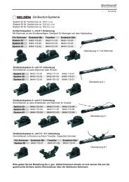
8b. Fitting cables in separate plastic conduitsFollow Instruction 1B.b, ”Cables in separate plastic conduits”. There are two executions for through-deckfitting on keel stepped masts.Alt. 1Plastic conduits (aft and/or forward) pass uninterruptedthrough seal at deck level.Alt. 2Plastic conduit ends above deck level seal. Cable(s)pass through conduit tube in centre of mast. (Oldertypes).Messenger linePlastic conduitConduit tubeDrainage holeSeal<strong>Mast</strong> coat upper edgeSealant injection holeDeck levelFig. 2.4No plastic conduitbelow sealFig. 2.3The type of execution can be checked by inspection through the two drain holes on the sides of the mast immediatelyabove the mast coat.Alt. 1 The after conduit may be sealed. If it is to be used then the sealant must be removed through the twoinjection holes which are sited either just above or just below the upper edge of the mast coat. Unfortunatelythis can be very difficult. Contact <strong>Seldén</strong> <strong>Mast</strong> for advice.(The mast coat may have to be temporarily pulled downwards on the mast).Alt. 2 The cables are drawn through the conduits by the messenger line. A new messenger line should be drawthrough parallel and at the same time as cables are drawn through in case one later wants to draw morecables. If no messenger line is present, one should be fitted as described in instruction 1B point b2.It can be awkward getting a messenger line through the conduit tube. A steel wire hook pushed througha drainage hole can be of valuable assistance in getting the messenger line to the conduit tube from themain conduit.Some mast heels have cable exit holes in their after part as shown in fig. 1.A.3.
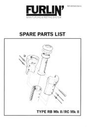
9FITTINGINSTRUCTION 3(E-sections with rounded after face)1 Equipment required• Cable• Bottled glue and fine nozzle; Glue type Cascol 1809• Adjustable spanner• Drill• Drill bit (Appr. 4 mm larger diameter than that of table)• 0,5 m length of thin line. Ø 3-4mm• Silieone sealant - for keel stepped masts only2 PreparationRemove the headbox and drill an exit hole at the mast head following Instruction 1A, point 2. Be careful ofexisting cables. Exit holes are already cast into the mast heel. (See instruction lA, fig. l.A.3).3 FittingCables are drawn upwards fram heel according toInstruction lA, fig. l.A.3. Read Instruction lA on how torun cable past the deck sealing on keel stepped masts.Lay the mast horizontally on two supports and angle itslightly as shown in fig. 3.1.Tension the cable weil and apply the glue to the cablealong the whole length of the mast.Fig. 3.1Glueing must be undertaken indoors or in dry weather: The glue must be left to set for 24 hours before movingthe mast.If several cables are to be fitted they should be glued close to each other and one at a time, with a couple ofhours’ time gap to allow the glue from the first application to gain same initial strength.The deck level seal must be replaced on keel stepped masts. See page 5.Do not overdose the glue. Cascol 1809 is a foaming glue and will fill the mast track ifoverdosing. Make sure to glue on a dry surface.Make a test outside the mast track or in a part of the mast track where no sail is hoisted.
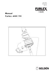
10FITTINGINSTRUCTION 4(Furling sections)1 Equipment required• Cable• Messenger line at least as long as the mast, and Ø 3-4 mm• Drill• Drill bit (if the cable is to exit between mast head and foot)2 FittingCables are fed through the conduits using the existing messenger line(s). On keel steppped masts the conduitspass through the deck level seal. A new messenger line is drawn through together with the cable, to remain insitu for possible future use.There are exit holes already in place at the mast head and heel.Previously drawn cable can hinder the drawing of new cable. In which ca se the old cable must first be removed- not forgetting to tie a new messenger line to it first before withdrawing it. There are exit holes at, or close to,the mast head and heel.A cable exit can easily be arranged on furling sections 232/126 and upwards. The exit hole must be drilledwith the greatest care so as not to damage existing cables. Lay the mast with its forward face uppermost so thatexisting cables lie in the after corner of the conduit. Drill the exit hole in the opposite corner. Drill the hole at aslight angle to minimise the risk of cable wear. A couple of tums of tape around the new cable will also help togive the cable a fairer exit run.Cable that is to exit between mast head and heel on furling sections 190/94-214/122, 235/116 have to lie freewithin the forward chamber: Stretch the cable hard to avoid slamming.ConduitConduitsSECTION RA 190/94-214/122, 235/116 SECTION RB/RC 232/126, 260/136, 290/150
11Extra equipmentWindex baseWindex base for 15° headbox angle. Part No. 508-549-01Windex extension base. Part No. 508-521-01Antenna or Wind instrumentation base for 15º headbox angleMedium size (100 x 40 mm) Part no. 508-563-01Larger size (180 x 65 mm) Part no. 508-541-01Antenna and Wind Instrumentation Base with placefor several antennae and instrumentsMedium size, 550 x 80 mm Part No. 508-556-01 + 508-508-01Ditto, with large base Part No. 508-556-01 + 508-541-01Large plate, 800 x 80 mm Part No. 508-559 -01Windex lightPart no. 526-153-01Anchor lightPart no. 526-163-01<strong>Mast</strong>head Combination Light(With or without anchor light).With anchor light, Part No. 526-021-02Without anchor light, Part No. 526-020-02
12DINGHIESKEELBOATSYACHTS<strong>Seldén</strong> <strong>Mast</strong> AB, SwedenTel +46 (0)31 69 69 00Fax +46 (0)31 29 71 37e-mail info@seldenmast.com<strong>Seldén</strong> <strong>Mast</strong> Limited, UKTel +44 (0) 1329 504000Fax +44 (0) 1329 504049e-mail info@seldenmast.co.ukThe <strong>Seldén</strong> Group is the world’s leading manufacturerof masts and rigging systems in carbonand aluminium for dinghies, keelboats and yachts.The Group consists of <strong>Seldén</strong> <strong>Mast</strong> AB in Sweden,<strong>Seldén</strong> <strong>Mast</strong> A/S in Denmark, <strong>Seldén</strong> <strong>Mast</strong> Ltd in<strong>Seldén</strong> <strong>Mast</strong> Inc., USATel +1 843-760-6278Fax +1 843-760-1220e-mail info@seldenus.com<strong>Seldén</strong> <strong>Mast</strong> A/S, DKTel +45 39 18 44 00Fax +45 39 27 17 00e-mail info@seldenmast.dk<strong>Seldén</strong> Mid Europe B.V., NLTel +31 (0) 111-698 120Fax +31 (0) 111-698 130e-mail info@seldenmast.nl<strong>Seldén</strong> <strong>Mast</strong> SAS, FRTel +33 (0) 251 362 110Fax +33 (0) 251 362 185e-mail info@seldenmast.frwww.seldenmast.comDealer:the UK, <strong>Seldén</strong> Mid Europe B.V. in the Netherlands,<strong>Seldén</strong> <strong>Mast</strong> SAS in France and <strong>Seldén</strong><strong>Mast</strong> Inc in the USA. Our well known brandsare <strong>Seldén</strong> and Furlex. The worldwide success ofFurlex has enabled us to build a network of over750 authorised dealers covering the world’s marinemarkets. So wherever you sail, you can be sureof fast access to our service,spare parts and know-how.595-557-E Printed in Sweden <strong>Seldén</strong> and Furlex are registered trademarks of <strong>Seldén</strong> <strong>Mast</strong> AB