Complete (13 MB) - Chris Alston's Chassisworks
Complete (13 MB) - Chris Alston's Chassisworks Complete (13 MB) - Chris Alston's Chassisworks
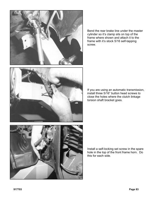
Bend the rear brake line under the mastercylinder so it’s clamp sits on top of theframe where shown and attach it to theframe with it’s stock 5/16 self-tappingscrew.If you are using an automatic transmission,install three 5/16” button head screws toclose the holes where the clutch linkagetorsion shaft bracket goes.Install a self-locking set screw in the sparehole in the top of the front frame horn. Dothis for each side.917703 Page 83
Install two 1/2” self-locking set screws inthe spare holes for the bumper mount inthe frame horn. Do this for each side.Reinstall the bumper brackets using thestock hardware in the correct holes.Reinstall the bumper and correctly align itwith the body.Installing Steering ShaftThis photo shows the flanged 1" DD u-jointthat attaches to the stock steering column.There are also two u-joints shown thatattach to the rack shaft. They are bothsized as 3/4-36 x 3/4 DD. The longeru-joint is a VIBRATION isolator styleu-joint. This type of u-joint will isolatesome of the road vibration from thesteering wheel. Both u-joints install thesame way, however, we will show theisolator style u-joint in the installationphotos.Page 84 917703
- Page 34 and 35: The caps are held in place with the
- Page 36 and 37: With both bushings on the bar, brin
- Page 38 and 39: Next, slide the link eyebolt onto t
- Page 41 and 42: Screw the spring seat adjuster onto
- Page 43 and 44: Install the lower shock spud first.
- Page 45 and 46: Add a drop of Loctite to the thread
- Page 47 and 48: Pack the outer wheel bearing as you
- Page 49 and 50: Next, install the Wilwood brake cal
- Page 51 and 52: Use a 3/8” wrench to tighten the
- Page 53 and 54: Move the spindle to full right lock
- Page 55 and 56: Insert one urethane bushing into ea
- Page 57 and 58: These optional stainless steel "spu
- Page 59 and 60: Installing Manual Transmission,Clut
- Page 61 and 62: Item 5916-F20-03 Turbo 400, 200-4R,
- Page 63 and 64: After you remove the engine, place
- Page 65 and 66: Use vise grip pliers and an end wre
- Page 67 and 68: Disconnect the clamps that attach t
- Page 69 and 70: Remove the bolts that attach the en
- Page 71 and 72: You need three people; one to opera
- Page 73 and 74: Lower the clip to the ground and pu
- Page 75 and 76: This is the correct orientation of
- Page 77 and 78: Place the top part of the mid and r
- Page 79 and 80: Install the lower half of the rear
- Page 81 and 82: Measure from the lip on the rocker
- Page 83: Attach the stock hook rod to the pa
- Page 87 and 88: Slide the splined end of the u-join
- Page 89 and 90: This is a photo of the completed in
- Page 91 and 92: Drill a 1/8” hole centered in the
- Page 93 and 94: Drill the remaining rivet holes sta
- Page 95 and 96: Installing HeadersSpecial Note: We
- Page 97 and 98: Installing SubframeConnectorsThe su
- Page 99 and 100: Once you have all the bolts removed
- Page 101 and 102: The spring clips can be just as tri
- Page 103 and 104: Slide a 3/8 inch flat washer over t
- Page 105 and 106: Page 104 917703
Bend the rear brake line under the mastercylinder so it’s clamp sits on top of theframe where shown and attach it to theframe with it’s stock 5/16 self-tappingscrew.If you are using an automatic transmission,install three 5/16” button head screws toclose the holes where the clutch linkagetorsion shaft bracket goes.Install a self-locking set screw in the sparehole in the top of the front frame horn. Dothis for each side.917703 Page 83


