Complete (13 MB) - Chris Alston's Chassisworks
Complete (13 MB) - Chris Alston's Chassisworks Complete (13 MB) - Chris Alston's Chassisworks
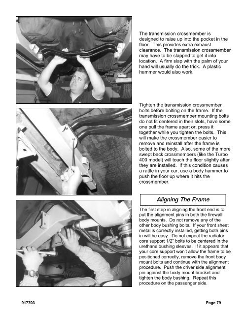
The transmission crossmember isdesigned to raise up into the pocket in thefloor. This provides extra exhaustclearance. The transmission crossmembermay have to be slapped to get it intolocation. A firm slap with the palm of yourhand will usually do the trick. A plastichammer would also work.Tighten the transmission crossmemberbolts before bolting on the frame. If thetransmission crossmember mounting boltsdo not fit centered in their slots, have someone pull the frame apart or, press ittogether while you tighten the bolts. Thiswill make the crossmember easier toremove and reinstall after the frame isbolted to the body. Also, some of the moreswept back crossmembers (like the Turbo400 model) will touch the floor slightly afterthey are installed. If this condition causesa rattle in your car, use a body hammer topush the floor up where it hits thecrossmember.Aligning The FrameThe first step in aligning the front end is toput the alignment pins in both the firewallbody mounts. Do not remove any of theother body bushing bolts. If your front sheetmetal is correctly installed, getting both pinsin will be easy. Do not expect the radiatorcore support 1/2” bolts to be centered in theurethane bushing sleeves. If it appears thatyour core support won’t allow the frame to bepositioned correctly, remove the front bodymount bolts and continue with the alignmentprocedure. Push the driver side alignmentpin against the body mount bracket andtighten the body bushing. Repeat thisprocedure on the passenger side.917703 Page 79
Measure from the lip on the rocker panel tothe side of the frame clip at the front of therocker panel and the rear of the frame.Bump the frame around until the frame isparallel with the rocker panel on each sideand the same distance from the frame tothe rocker lip on each side. If the lip underthe rocker panel is not straight, use a bodyhammer and dolly to straighten it beforemeasuring. Try to bump the frame aroundso that the largest measured differencebetween any two of the four rocker panellips is less than 1/4 inch.After you have finished the previous step,verify the distance from the rear framegauge hole to the back of the frame. Thelength should be within 1/8 of an inch fromside to side.Page 80 917703
- Page 30 and 31: Next, set the bar level and tighten
- Page 32 and 33: Next, you can final assemble the ti
- Page 34 and 35: The caps are held in place with the
- Page 36 and 37: With both bushings on the bar, brin
- Page 38 and 39: Next, slide the link eyebolt onto t
- Page 41 and 42: Screw the spring seat adjuster onto
- Page 43 and 44: Install the lower shock spud first.
- Page 45 and 46: Add a drop of Loctite to the thread
- Page 47 and 48: Pack the outer wheel bearing as you
- Page 49 and 50: Next, install the Wilwood brake cal
- Page 51 and 52: Use a 3/8” wrench to tighten the
- Page 53 and 54: Move the spindle to full right lock
- Page 55 and 56: Insert one urethane bushing into ea
- Page 57 and 58: These optional stainless steel "spu
- Page 59 and 60: Installing Manual Transmission,Clut
- Page 61 and 62: Item 5916-F20-03 Turbo 400, 200-4R,
- Page 63 and 64: After you remove the engine, place
- Page 65 and 66: Use vise grip pliers and an end wre
- Page 67 and 68: Disconnect the clamps that attach t
- Page 69 and 70: Remove the bolts that attach the en
- Page 71 and 72: You need three people; one to opera
- Page 73 and 74: Lower the clip to the ground and pu
- Page 75 and 76: This is the correct orientation of
- Page 77 and 78: Place the top part of the mid and r
- Page 79: Install the lower half of the rear
- Page 83 and 84: Attach the stock hook rod to the pa
- Page 85 and 86: Install two 1/2” self-locking set
- Page 87 and 88: Slide the splined end of the u-join
- Page 89 and 90: This is a photo of the completed in
- Page 91 and 92: Drill a 1/8” hole centered in the
- Page 93 and 94: Drill the remaining rivet holes sta
- Page 95 and 96: Installing HeadersSpecial Note: We
- Page 97 and 98: Installing SubframeConnectorsThe su
- Page 99 and 100: Once you have all the bolts removed
- Page 101 and 102: The spring clips can be just as tri
- Page 103 and 104: Slide a 3/8 inch flat washer over t
- Page 105 and 106: Page 104 917703
The transmission crossmember isdesigned to raise up into the pocket in thefloor. This provides extra exhaustclearance. The transmission crossmembermay have to be slapped to get it intolocation. A firm slap with the palm of yourhand will usually do the trick. A plastichammer would also work.Tighten the transmission crossmemberbolts before bolting on the frame. If thetransmission crossmember mounting boltsdo not fit centered in their slots, have someone pull the frame apart or, press ittogether while you tighten the bolts. Thiswill make the crossmember easier toremove and reinstall after the frame isbolted to the body. Also, some of the moreswept back crossmembers (like the Turbo400 model) will touch the floor slightly afterthey are installed. If this condition causesa rattle in your car, use a body hammer topush the floor up where it hits thecrossmember.Aligning The FrameThe first step in aligning the front end is toput the alignment pins in both the firewallbody mounts. Do not remove any of theother body bushing bolts. If your front sheetmetal is correctly installed, getting both pinsin will be easy. Do not expect the radiatorcore support 1/2” bolts to be centered in theurethane bushing sleeves. If it appears thatyour core support won’t allow the frame to bepositioned correctly, remove the front bodymount bolts and continue with the alignmentprocedure. Push the driver side alignmentpin against the body mount bracket andtighten the body bushing. Repeat thisprocedure on the passenger side.917703 Page 79


