Complete (13 MB) - Chris Alston's Chassisworks
Complete (13 MB) - Chris Alston's Chassisworks Complete (13 MB) - Chris Alston's Chassisworks
from cachassisworks.com
More from this publisher
13.07.2015
Views
Disconnect the brake line clamp by thesteering box.From under the floor, disconnect bothbrake line clamps on the outside of thedriver side frame rail.Remove the battery tray for easier accessto the front frame bolts.917703 Page 67
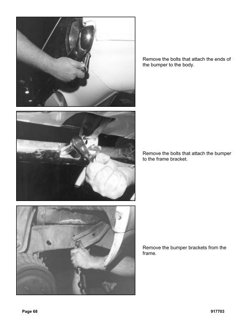
Remove the bolts that attach the ends ofthe bumper to the body.Remove the bolts that attach the bumperto the frame bracket.Remove the bumper brackets from theframe.Page 68 917703
- Page 17 and 18: Next, install the shock simulator a
- Page 20: With the cotter pin installed, use
- Page 26 and 27: Install the tie rod end in the stee
- Page 28 and 29: First, check and record the camber
- Page 30 and 31: Next, set the bar level and tighten
- Page 32 and 33: Next, you can final assemble the ti
- Page 34 and 35: The caps are held in place with the
- Page 36 and 37: With both bushings on the bar, brin
- Page 38 and 39: Next, slide the link eyebolt onto t
- Page 41 and 42: Screw the spring seat adjuster onto
- Page 43 and 44: Install the lower shock spud first.
- Page 45 and 46: Add a drop of Loctite to the thread
- Page 47 and 48: Pack the outer wheel bearing as you
- Page 49 and 50: Next, install the Wilwood brake cal
- Page 51 and 52: Use a 3/8” wrench to tighten the
- Page 53 and 54: Move the spindle to full right lock
- Page 55 and 56: Insert one urethane bushing into ea
- Page 57 and 58: These optional stainless steel "spu
- Page 59 and 60: Installing Manual Transmission,Clut
- Page 61 and 62: Item 5916-F20-03 Turbo 400, 200-4R,
- Page 63 and 64: After you remove the engine, place
- Page 65 and 66: Use vise grip pliers and an end wre
- Page 67: Disconnect the clamps that attach t
- Page 71 and 72: You need three people; one to opera
- Page 73 and 74: Lower the clip to the ground and pu
- Page 75 and 76: This is the correct orientation of
- Page 77 and 78: Place the top part of the mid and r
- Page 79 and 80: Install the lower half of the rear
- Page 81 and 82: Measure from the lip on the rocker
- Page 83 and 84: Attach the stock hook rod to the pa
- Page 85 and 86: Install two 1/2” self-locking set
- Page 87 and 88: Slide the splined end of the u-join
- Page 89 and 90: This is a photo of the completed in
- Page 91 and 92: Drill a 1/8” hole centered in the
- Page 93 and 94: Drill the remaining rivet holes sta
- Page 95 and 96: Installing HeadersSpecial Note: We
- Page 97 and 98: Installing SubframeConnectorsThe su
- Page 99 and 100: Once you have all the bolts removed
- Page 101 and 102: The spring clips can be just as tri
- Page 103 and 104: Slide a 3/8 inch flat washer over t
- Page 105 and 106: Page 104 917703
Remove the bolts that attach the ends ofthe bumper to the body.Remove the bolts that attach the bumperto the frame bracket.Remove the bumper brackets from theframe.Page 68 917703


