Complete (13 MB) - Chris Alston's Chassisworks
Complete (13 MB) - Chris Alston's Chassisworks Complete (13 MB) - Chris Alston's Chassisworks
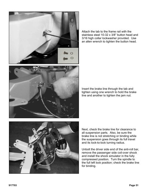
Attach the tab to the frame rail with thestainless steel 10-32 x 3/8” button head and3/16 high collar lockwasher provided. Usean allen wrench to tighten the button head.Insert the brake line through the tab andtighten using one wrench to hold the brakeline and another to tighten the jam nut.Next, check the brake line for clearance toall suspension parts. Also, be sure thebrake line is not stretching or binding whilethe suspension goes through its full traveland its lock-to-lock turning radius.Unbolt the driver side end of the anti-roll bar,remove the passenger side coil-over shockand install the shock simulator in the fullycompressed position. Turn the spindle tothe full left lock position; check the brake linefor binding.917703 Page 51
Move the spindle to full right lock, check thebrake line for any binding.Move the shock simulator to the fullextension setting, turn the spindle to full rightlock position. Check the brake to be sure itis not stretched.Turn the spindle to the full left lock position;check the brake line for binding. Repeat thisprocedure at the ride height setting.Page 52 917703
- Page 1 and 2: READ ALL INSTRUCTIONS COMPLETELY AN
- Page 3 and 4: CONGRATULATIONSYou have purchased t
- Page 5 and 6: DISCLAIMER OF WARRANTYPurchasers re
- Page 7 and 8: Installing SuspensionNote: The phot
- Page 9 and 10: The balljoint is then screwed into
- Page 11 and 12: Thread the balljoint in as far as p
- Page 13 and 14: Next, chase the threads in the lowe
- Page 15 and 16: If you have to remove the lower A-a
- Page 17 and 18: Next, install the shock simulator a
- Page 20: With the cotter pin installed, use
- Page 26 and 27: Install the tie rod end in the stee
- Page 28 and 29: First, check and record the camber
- Page 30 and 31: Next, set the bar level and tighten
- Page 32 and 33: Next, you can final assemble the ti
- Page 34 and 35: The caps are held in place with the
- Page 36 and 37: With both bushings on the bar, brin
- Page 38 and 39: Next, slide the link eyebolt onto t
- Page 41 and 42: Screw the spring seat adjuster onto
- Page 43 and 44: Install the lower shock spud first.
- Page 45 and 46: Add a drop of Loctite to the thread
- Page 47 and 48: Pack the outer wheel bearing as you
- Page 49 and 50: Next, install the Wilwood brake cal
- Page 51: Use a 3/8” wrench to tighten the
- Page 55 and 56: Insert one urethane bushing into ea
- Page 57 and 58: These optional stainless steel "spu
- Page 59 and 60: Installing Manual Transmission,Clut
- Page 61 and 62: Item 5916-F20-03 Turbo 400, 200-4R,
- Page 63 and 64: After you remove the engine, place
- Page 65 and 66: Use vise grip pliers and an end wre
- Page 67 and 68: Disconnect the clamps that attach t
- Page 69 and 70: Remove the bolts that attach the en
- Page 71 and 72: You need three people; one to opera
- Page 73 and 74: Lower the clip to the ground and pu
- Page 75 and 76: This is the correct orientation of
- Page 77 and 78: Place the top part of the mid and r
- Page 79 and 80: Install the lower half of the rear
- Page 81 and 82: Measure from the lip on the rocker
- Page 83 and 84: Attach the stock hook rod to the pa
- Page 85 and 86: Install two 1/2” self-locking set
- Page 87 and 88: Slide the splined end of the u-join
- Page 89 and 90: This is a photo of the completed in
- Page 91 and 92: Drill a 1/8” hole centered in the
- Page 93 and 94: Drill the remaining rivet holes sta
- Page 95 and 96: Installing HeadersSpecial Note: We
- Page 97 and 98: Installing SubframeConnectorsThe su
- Page 99 and 100: Once you have all the bolts removed
- Page 101 and 102: The spring clips can be just as tri
Attach the tab to the frame rail with thestainless steel 10-32 x 3/8” button head and3/16 high collar lockwasher provided. Usean allen wrench to tighten the button head.Insert the brake line through the tab andtighten using one wrench to hold the brakeline and another to tighten the jam nut.Next, check the brake line for clearance toall suspension parts. Also, be sure thebrake line is not stretching or binding whilethe suspension goes through its full traveland its lock-to-lock turning radius.Unbolt the driver side end of the anti-roll bar,remove the passenger side coil-over shockand install the shock simulator in the fullycompressed position. Turn the spindle tothe full left lock position; check the brake linefor binding.917703 Page 51


