Recommended Equipment ListThis list will give you a good idea of the necessary tools required to complete this installation.There will be additional items needed.Hand Tools Adjustable wrench Allen wrench set Anti-seize compound Brake line wrench Center punch Clecos & pliers 1/8 size Combination wrenches 3/8 to 3/4” Vise grip pliers Drill bit size 1/8 (.125) Level Loctite #242 thread lock Philips screwdriver sizes #1 & #2 Pry bar Wire brush Socket set 3/8 to 3/4” with 3/8 drive 15/16” socket with 1/2” drive ratchet Steel & plastic head hammers Straight blade screwdriver Pliers Tape measure Tap handle small and medium Tap sizes: 10-32, 3/8-16, 7/16-14, 1/2-<strong>13</strong>,5/8-18 Needle nose pliersShop Equipment Floor jack Jack stands –quantity 4 Digital level 3/8” electric drillTorque Specification ChartDESCRIPTIONTORQUEDESCRIPTIONTORQUEA-arm pivot studs50 lb-ftFrame mounting bolt 5/8-11 x 380 lb-ftAntiroll bar clamp socket head allens3/8-16 x 2 1/2”Antiroll bar link eyebolt button head allen3/8-16 x 3/4”Antiroll bar link eyebolt socket head allen3/8-16 x 2 1/4”20 lb-ft20 lb-ft20 lb-ftMotor mount spudsRack clamp socket head allens1/2-<strong>13</strong> x 2”Rack clamp caps socket head allens5/16-18 x 1”Shock spuds20 lb-ft45 lb-ft15 lb-ft20 lb-ftBalljoints150 lb-ftShock bolts 1/2-20 x 2 1/2”45 lb-ftBalljoint studs105 lb-ftTie rod stud60 lb-ftCaliper socket head allens 3/8-16 x 1 3/8”30 lb-ftWheel studs 1/2-20 x 2 1/4” 12 point40 lb-ftFrame mounting bolt 1/2-<strong>13</strong> x 2 1/2”45 lb-ftWe recommend applying a small amount of Loctite on all fasteners except the balljoint studs, and the tie rod studs.917703 Page 3
DISCLAIMER OF WARRANTYPurchasers recognize and understand that products and services manufactured, provided, and/or sold byCHRIS ALSTON’S CHASSISWORKS, INC., are exposed to many varied conditions due to the manner inwhich they are used. Purchasers assume the responsibility to develop a Maintenance Procedure toidentify and replace worn components before they fail. Your Maintenance Procedure must include everycomponent on the vehicle. CHRIS ALSTON’S CHASSISWORKS, INC., makes no claims or guaranteesthat any product or service is designed or intended to comply with any industry standards or governmentregulations. CHRIS ALSTON’S CHASSISWORKS, INC., makes no claims or guarantees in reference toany acceptance for use of its products or services by any entity or racing association, or that its productscan legally be installed on any vehicle that operates on a public highway.CHRIS ALSTON’S CHASSISWORKS, INC., reserves the right to make changes or improvements indesign, materials or specifications or make product changes without incurring any obligation to replace,change or improve products manufactured prior hereto.There are NO WARRANTIES, either expressed or implied. There is no warranty of merchantability.Neither the seller nor manufacturer will be liable for ANY loss, damage or injury direct or indirect, arisingfrom the use or inability to determine the appropriate use of any product. Buyer will not rely onCHASSISWORKS skill or judgment to select or furnish the proper part or equipment for their application.Buyer expressly affirms that they are relying upon their own skill and judgment to select and purchasesuitable goods.Before any attempt at installation, all drawings and/or instruction sheets must be completely reviewed todetermine the suitability of the product for its intended use and that the buyer has the skills required toinstall and maintain the product. Buyer assumes all responsibility and risk for correct installation. CHRISALSTON’S CHASSISWORKS, INC., accepts no responsibility for failure to read, or understand theinstallation guidelines. All products are intended for racing or off-road use and may not be legal forhighway use. The information contained in this Installation Guide is correct to the best of our know-ledgeand belief, having been compiled from reliable sources. However, CHRIS ALSTON’S CHASSISWORKS,INC., cannot assume responsibility for possible error. BUYER IS RESPONSIBLE FOR DETERMININGTHE SUITABILITY OF ANY AND ALL PRODUCTS PURCHASED FROM CHRIS ALSTON’SCHASSISWORKS, INC.It is expressly understood and agreed between purchasers and <strong>Chris</strong> Alston’s <strong>Chassisworks</strong>, Inc., that aspart of the bargain between CHRIS ALSTON’S CHASSISWORKS, INC., and purchasers, and inconsideration of doing business with each other, all purchasers take, select and purchase said racingparts, equipment any and all inventory, or services from CHRIS ALSTON’S CHASSISWORKS, INC., “as is”and “with all faults” and CHRIS ALSTON’S CHASSISWORKS, INC., shall always provide purchasers with afull and complete opportunity to examine, at purchasers’ leisure and convenience, any racing parts andequipment, any and all inventory, or services when purchasing or contemplating purchasing from CHRISALSTON’S CHASSISWORKS, INC. Use of CHRIS ALSTON’S CHASSISWORKS, INC., productsconstitutes acceptance of this agreement in its entirety.BUYER IS RESPONSIBLE FOR DETERMINING THE SUITABILITY OF ANY AND ALL PRODUCTSPURCHASED FROM CHRIS ALSTON’S CHASSISWORKS, INC. NO PART, COMPONENT,INVENTORY, OR SERVICE MANUFACTURED OR SOLD BY CHRIS ALSTON’S CHASSISWORKS, INC.,IS DESIGNED OR INTENDED TO PREVENT INJURY OR DEATH.Purchasers understand and agree that no officer, director, employee, salesperson, or agent of CHRISALSTON’S CHASSISWORKS, INC., has any authority to make any statement contrary to the terms of thisagreement. CHRIS ALSTON’S CHASSISWORKS, INC., disavows any statement contrary to what isherein above written.Page 4 917703
- Page 1 and 2: READ ALL INSTRUCTIONS COMPLETELY AN
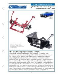
- Page 3: CONGRATULATIONSYou have purchased t
- Page 7 and 8: Installing SuspensionNote: The phot
- Page 9 and 10: The balljoint is then screwed into
- Page 11 and 12: Thread the balljoint in as far as p
- Page 13 and 14: Next, chase the threads in the lowe
- Page 15 and 16: If you have to remove the lower A-a
- Page 17 and 18: Next, install the shock simulator a
- Page 20: With the cotter pin installed, use
- Page 26 and 27: Install the tie rod end in the stee
- Page 28 and 29: First, check and record the camber
- Page 30 and 31: Next, set the bar level and tighten
- Page 32 and 33: Next, you can final assemble the ti
- Page 34 and 35: The caps are held in place with the
- Page 36 and 37: With both bushings on the bar, brin
- Page 38 and 39: Next, slide the link eyebolt onto t
- Page 41 and 42: Screw the spring seat adjuster onto
- Page 43 and 44: Install the lower shock spud first.
- Page 45 and 46: Add a drop of Loctite to the thread
- Page 47 and 48: Pack the outer wheel bearing as you
- Page 49 and 50: Next, install the Wilwood brake cal
- Page 51 and 52: Use a 3/8” wrench to tighten the
- Page 53 and 54: Move the spindle to full right lock
- Page 55 and 56:
Insert one urethane bushing into ea
- Page 57 and 58:
These optional stainless steel "spu
- Page 59 and 60:
Installing Manual Transmission,Clut
- Page 61 and 62:
Item 5916-F20-03 Turbo 400, 200-4R,
- Page 63 and 64:
After you remove the engine, place
- Page 65 and 66:
Use vise grip pliers and an end wre
- Page 67 and 68:
Disconnect the clamps that attach t
- Page 69 and 70:
Remove the bolts that attach the en
- Page 71 and 72:
You need three people; one to opera
- Page 73 and 74:
Lower the clip to the ground and pu
- Page 75 and 76:
This is the correct orientation of
- Page 77 and 78:
Place the top part of the mid and r
- Page 79 and 80:
Install the lower half of the rear
- Page 81 and 82:
Measure from the lip on the rocker
- Page 83 and 84:
Attach the stock hook rod to the pa
- Page 85 and 86:
Install two 1/2” self-locking set
- Page 87 and 88:
Slide the splined end of the u-join
- Page 89 and 90:
This is a photo of the completed in
- Page 91 and 92:
Drill a 1/8” hole centered in the
- Page 93 and 94:
Drill the remaining rivet holes sta
- Page 95 and 96:
Installing HeadersSpecial Note: We
- Page 97 and 98:
Installing SubframeConnectorsThe su
- Page 99 and 100:
Once you have all the bolts removed
- Page 101 and 102:
The spring clips can be just as tri
- Page 103 and 104:
Slide a 3/8 inch flat washer over t
- Page 105 and 106:
Page 104 917703