Complete (13 MB) - Chris Alston's Chassisworks
Complete (13 MB) - Chris Alston's Chassisworks Complete (13 MB) - Chris Alston's Chassisworks
After the application of another dab of antiseize,the rod ends are threaded into theA-arms, until the jam nuts are snug againstthe arm itself.This step must be done carefully becausethe upper and lower A-arm mounts arethreaded and welded to the frame. Use the5/8-18 tap to chase the threads on the frontand backsides of both upper mounts. Blowany remaining particles out of the hole withan air hose.917703 Page 11
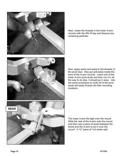
Next, chase the threads in the lower A-armmounts with the 5/8-18 tap and blowout anyremaining particles.Now, apply some anti-seize to the threads ofthe pivot stud. Also put anti-seize inside thebore of the A-arm mounts. Insert one of thelower A-arm pivot studs and then run it in allthe way to its stop, it should go in easy. Usethe same procedure to verify all of the pivotstuds will easily thread into their mountinglocations.REARThe lower A-arm fits tight over the mount.Slide the rear of the A-arm onto the mountand then use a piece of wood between theframe and the A-arm to pry it over themount. A 12” piece of 1x2 works well.Page 12 917703
- Page 1 and 2: READ ALL INSTRUCTIONS COMPLETELY AN
- Page 3 and 4: CONGRATULATIONSYou have purchased t
- Page 5 and 6: DISCLAIMER OF WARRANTYPurchasers re
- Page 7 and 8: Installing SuspensionNote: The phot
- Page 9 and 10: The balljoint is then screwed into
- Page 11: Thread the balljoint in as far as p
- Page 15 and 16: If you have to remove the lower A-a
- Page 17 and 18: Next, install the shock simulator a
- Page 20: With the cotter pin installed, use
- Page 26 and 27: Install the tie rod end in the stee
- Page 28 and 29: First, check and record the camber
- Page 30 and 31: Next, set the bar level and tighten
- Page 32 and 33: Next, you can final assemble the ti
- Page 34 and 35: The caps are held in place with the
- Page 36 and 37: With both bushings on the bar, brin
- Page 38 and 39: Next, slide the link eyebolt onto t
- Page 41 and 42: Screw the spring seat adjuster onto
- Page 43 and 44: Install the lower shock spud first.
- Page 45 and 46: Add a drop of Loctite to the thread
- Page 47 and 48: Pack the outer wheel bearing as you
- Page 49 and 50: Next, install the Wilwood brake cal
- Page 51 and 52: Use a 3/8” wrench to tighten the
- Page 53 and 54: Move the spindle to full right lock
- Page 55 and 56: Insert one urethane bushing into ea
- Page 57 and 58: These optional stainless steel "spu
- Page 59 and 60: Installing Manual Transmission,Clut
- Page 61 and 62: Item 5916-F20-03 Turbo 400, 200-4R,
Next, chase the threads in the lower A-armmounts with the 5/8-18 tap and blowout anyremaining particles.Now, apply some anti-seize to the threads ofthe pivot stud. Also put anti-seize inside thebore of the A-arm mounts. Insert one of thelower A-arm pivot studs and then run it in allthe way to its stop, it should go in easy. Usethe same procedure to verify all of the pivotstuds will easily thread into their mountinglocations.REARThe lower A-arm fits tight over the mount.Slide the rear of the A-arm onto the mountand then use a piece of wood between theframe and the A-arm to pry it over themount. A 12” piece of 1x2 works well.Page 12 917703


