1962-1967 Nova: Rear Torque Arm Suspension - Total Cost Involved
1962-1967 Nova: Rear Torque Arm Suspension - Total Cost Involved
1962-1967 Nova: Rear Torque Arm Suspension - Total Cost Involved

You also want an ePaper? Increase the reach of your titles
YUMPU automatically turns print PDFs into web optimized ePapers that Google loves.
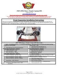
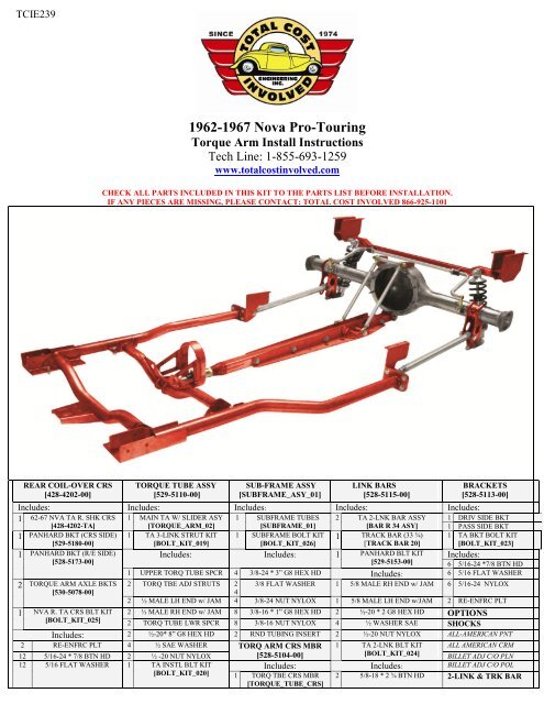
TCIE239<strong>1962</strong>-<strong>1967</strong> <strong>Nova</strong> Pro-Touring<strong>Torque</strong> <strong>Arm</strong> Install InstructionsTech Line: 1-855-693-1259www.totalcostinvolved.comCHECK ALL PARTS INCLUDED IN THIS KIT TO THE PARTS LIST BEFORE INSTALLATION.IF ANY PIECES ARE MISSING, PLEASE CONTACT: TOTAL COST INVOLVED 866-925-1101REAR COIL-OVER CRS[428-4202-00]TORQUE TUBE ASSY[529-5110-00]SUB-FRAME ASSY[SUBFRAME_ASY_01]LINK BARS[528-5115-00]BRACKETS[528-5113-00]Includes: Includes: Includes: Includes: Includes:1 62-67 NVA TA R. SHK CRS 1 MAIN TA W/ SLIDER ASY 1 SUBFRAME TUBES 2 TA 2-LNK BAR ASSY 1 DRIV SIDE BKT[428-4202-TA][TORQUE_ARM_02][SUBFRAME_01][BAR R 34 ASY] 1 PASS SIDE BKT1 PANHARD BKT (CRS SIDE) 1 TA 3-LINK STRUT KIT 1 SUBFRAME BOLT KIT 1 TRACK BAR (33 ¾) 1 TA BKT BOLT KIT[529-5180-00][BOLT_KIT_019][BOLT_KIT_026][TRACK BAR 20][BOLT_KIT_023]1 PANHARD BKT (R/E SIDE)[528-5173-00]2 TORQUE ARM AXLE BKTS[530-5078-00]Includes: Includes: 1 PANHARD BLT KIT Includes:[529-5153-00] 6 5/16-24 *7/8 BTN HD1 UPPER TORQ TUBE SPCR 4 3/8-24 * 3” G8 HEX HD Includes: 6 5/16 FLAT WASHER2 TORQ TBE ADJ STRUTS 2 3/8 FLAT WASHER 1 5/8 MALE RH END w/ JAM 6 5/16-24 NYLOX42 ½ MALE LH END w/ JAM 4 3/8-24 NUT NYLOX 1 5/8 MALE LH END w/JAM 2 RE-ENFRC PLT1 NVA R. TA CRS BLT KIT 2 ½ MALE RH END w/ JAM 8 3/8-16 * 1” G8 HEX HD 2 ½-20 * 2 G8 HEX HD OPTIONS[BOLT_KIT_025] 2 TORQ TUBE LWR SPCR 8 3/8-16 NUT NYLOX 4 ½ WASHER SAE SHOCKSIncludes: 2 ½-20* 8” G8 HEX HD 2 RND TUBING INSERT 2 ½-20 NUT NYLOX ALL-AMERICAN PNT2 RE-ENFRC PLT 4 ½ SAE WASHER TORQ ARM CRS MBR 1 TA 2-LNK BLT KIT ALL AMERICAN CRM12 5/16-24 * 7/8 BTN HD 2 ½ -20 NUT NYLOX [528-5104-00][BOLT_KIT_024]BILLET ADJ C/O PLN12 5/16 FLAT WASHER 1 TA INSTL BLT KIT[BOLT_KIT_020]Includes: Includes: BILLET ADJ C/O POL2 5/8-18 * 2 ¾ BTN HD 2-LINK & TRK BAR1 TORQ TBE CRS MBR[TORQUE_TUBE_CRS]
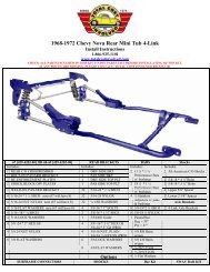
12 5/16-24 NUT NYLOX Includes: 1 TORQ ARM CRS BLT 2 5/8 NUT NYLOX STEEL1 1/2 -20*3 G8 HEX HD 1 ½-20 * 3” G8 HEX HDKIT[BOLT_KIT_027]2 ½-20 * 3” G8 HEX HD CHROME2 ½ SAE WASHER 1 ½-20 * 3 ½ “ G8 HEX HD Includes: 4 ½ SAE WASHER POLISHED1 ½-20 NUT NYLOX G8 4 ½ SAE WASHER 4 3/8-16 * 1” G8 HEX HD 2 ½ -20 NUT NYLOX SWAY BAR KIT1 ½-20 NUT NYLOX 8 3/8 FLAT WASHER PLAIN[428-4854-00]1 ½-20 NUT NYLOX JAM 4 3/8-16 NUT NYLOX CHROME[428-4854-01]OPTIONS ContinuedComplete <strong>Rear</strong> End Assembly w/BrakesThe car needs to be securely positioned and level as possible from side to side and on tall jack stands orpreferably a hoist to facilitate removal of the old components and much easier installation of new components.Temporarily remove the rear seat to facilitate drilling through the floor for the reinforcing plate.It is highly recommended that all components be fitted and installed first before painting or powder coating.The cars are 40 years old plus and the under carriage can shift and move over time and minor adjustments mayhave to be made. On this car the left side spring hanger had shifted slightly. That is why the link bar bracket isslotted where the ½ inch bolt attaches the link bar to compensate for minor shifting.1. Removing Flange on Stock Spring Hanger.The stock spring hanger has a 7/16 inch hole. This willhave to be drilled or reamed to ½ inch to accept the ½ inchbolt used on the adjustor end of the link bars.The jack plates will have to be removed for bar clearanceas shown with arrow.The inside flange on the stock spring hanger will interferewith the 1¼ inch link bar when installed and needs to havethe flange partially removed for clearance.Attach one of the bars to the bracket with the ½ inch boltand check for clearance and remove only as much materialas needed so as to retain rigidity. A small portion of theflange should remain.2. Mounting Link Bar Bracket.Note: There is a left and right hand link bar bracket. Theleft side (driver’s side) is shown on the picture.Position the bracket as picture flush against the front sideof the stock spring bracket and against the frame rail withthe top flange pressed up against the floor. Use theprevious ½ inch bolt and the inner sleeve from thestainless adjustor and fasten the bracket to the stockhanger. Clamp bracket as picture before drilling top holes.
3. Drilling Link Bar Bracket Holes.With the bracket securely clamped, use a long 5/16 drillbit and drill one hole and install one of the 5/16 buttonhead bolts, temporally install nut on the bolt on the insideof the trunk and tighten. This will keep all the holesaligned as you finish drilling the remaining holes.4. Installing the Inside Reinforcing Plates.After all the holes are drilled remove the temporary nutand place the 3-hole reinforcing plate over the holes andinstall the remaining button head bolts, washers and locknuts and tighten.Note:The 5/16 inch button head bolts can be installed asshown or reversed with the nut on the bottom.5. Drilling 3/8 inch Holes in Stock Spring Hanger.With the car level from side to side place a level on theside of the bracket to make sure it is 90 degrees square tothe ground and clamp securely as pictured. On this car oneside was perfect but on the other side I had to pry thebracket down on the outside edge to get it level beforeclamping. A straight edge aligned across the bottom edgeof the bracket works also. This is critical because the subframeconnectors will not be clocked correctly.Transfer punch a center and drill the bottom hole firstwith a ¼ inch then out to 3/8 inch. Install 3/8 inch bolt,tighten and drill remaining top hole.
6. Installing Sub-Frame Connectors.Note: There is a left and right hand sub-frameconnector. The left side (driver’s side) is shown.Position the rear flange against the new frame bracketand install the 2 lower 3/8 inch bolts and lightly tighten.Using a soft hammer tap the front saddle over the frontframe rail and install the 2 remaining bolts and tighten.Note: The rear floor pan on the driver’s side on this carhad drooped and needed to be pushed up 1/4 inch for subframeconnector clearance.7. Drilling Frame Rail for Front of Sub-Connector.Using an adjustable stand or jack push the front of the subframeconnector saddle up until the top of the saddlepresses against the upper floor flange on the frame rail.Using a 3/8 inch drill bit and using the bracket as a guidedrill one hole as pictured. Temporarily place a short 3/8inch bolt in the hole to retain hole alignment and drill thesecond hole. Repeat process on the opposite side. Installthe 3/8 x 3½ inch bolts, washers, lock nuts and tighten.8. Locating and Installing Coil-Over Cross-Member.The cross-member will only fit one way due to the taperof the frame rails. The cross-member is wider at the rearand narrower at the front plus the ½ inch hole in the 1½square section mounts the panhard bracket on the right(passenger) side. Push the cross-member over the framerails up tight against the frame rail floor flange andsupport with adjustable stands. Clamp a flat bar to thefront face of the cross-member and measure level aspictured to the center of the ½ inch frame bracket hole30¼ inches. Tap cross-member for or aft to get correctmeasurement. Repeat process on opposite side anddouble check both sides twice.9. Drilling Cross-Member Bracket Holes.Using a long 5/16 inch drill bit drill one hole and install a5/16 in bolt to retain hole alignment. Do the same to theopposite side. Drill the remaining holes.Note:You will have to drill the inside center hole from thetrunk area after you have partially installed the 6 holereinforcing plate as pictured. Finish by installing the 5/16inch button head bolts, washers and locknuts in desireddirection.
10. Installing Transmission Cross-Member.The transmission cross-member is installed with the endangle tabs sitting on top of the front sub-frame connectorbracket flanges with multiple holes for a variety oftransmission applications. Using the 3/8 x 1 inch bolts,washers and locknuts, fasten the cross-member as per yourtransmission application as pictured.11. Installing the <strong>Torque</strong> <strong>Arm</strong> Cross-Member.The <strong>Torque</strong> <strong>Arm</strong> cross-member is installed with the endangle tabs on the bottom side of the brackets that arewelded to the sub-frame connectors with the driveshaftloop facing rearward. Install the 3/8 x 1 inch bolts,washers and lock nuts. Center the driveshaft loop in thetunnel before tightening bolts.12. Axle Housing Bracket Measurements.<strong>1962</strong>-67 <strong>Nova</strong>Housing width-------49½ inches; Axle flange to axle flange 54½ inches
13. Installing Two Link Brackets & Panhard Bracket.The axle brackets are designed to slide over a 3 inch axletube before the bearing flange housings are installed. If thebearing ends are already on the axle bracket the 3 inch ribscan be cut 90 degrees to the flat shock mounting face andre-attached after the bracket is tacked on. The brackets arepositioned on 37½ inch centers.The flat rear surface of the axle bracket needs to beparallel with the front mounting surface of the 3 rdmember. (aka 0 pinion angle)The panhard bar bracket is installed onto the back of thedriver’s side axle bracket with the channel facing out andthe inner curved radius inside the outer axle bracket rib upagainst the 3 in axle tube rotated down against the rearface of the axle bracket.The flat rear surface of the axle bracket needs to beparallel with the front mounting surface of the 3 rdmember. (aka 0 pinion angle)13. Installing Two Link Brackets & Panhard Bracket.The axle brackets are designed to slide over a 3 inch axletube before the bearing flange housings are installed. If thebearing ends are already on the axle bracket the 3 inch ribscan be cut 90 degrees to the flat shock mounting face andre-attached after the bracket is tacked on. The brackets arepositioned on 37½ inch centers.The flat rear surface of the axle bracket needs to beparallel with the front mounting surface of the 3 rdmember. (aka 0 pinion angle)The panhard bar bracket is installed onto the back of thedriver’s side axle bracket with the channel facing out andthe inner curved radius inside the outer axle bracket rib upagainst the 3 in axle tube rotated down against the rearface of the axle bracket.
14. Installing <strong>Torque</strong> <strong>Arm</strong> Tabs on Housing.The torque arm tabs are welded on by using the suppliedfixture tool. Bolt fixture to the lowest 2 third member boltsflat against the housing flange. Bolt on the two suppliedtabs using the ½ by 3½ inch bolt and with the longer tab tothe passenger side of the housing. Bottom of tabs mayneed sanding to fit. Weld outside and wrap welds also tothe inside.Note:Housing picture upside down for ease of welding tabs.15. Welding Axle and Panhard Brackets.Finish welding the axle brackets and the panhard barbracket as pictured.If an optional sway bar is being used the sway barbrackets are located on the front of the axle tubes at axlecenterline on 33 inch centers.16. Installing Pinion Support Brackets.The pinion support brackets are installed next. Using thefurnished fixture tool, using the three 3/8 by 24 nuts, boltthe fixture onto the top three studs of the third memberhousing with the locating tabs facing forward. Bolt the ¼inch laser cut brackets to the outside of the fixture toolusing the two ½ inch bolts with the wider bracket on thepassenger side and the shorter bracket on the driver side.Note; Some fitting may be required to get the bracketflush with the top of the third member. The distancebetween the 2 brackets should be 6.45 inches afterwelding. Because of the distortion from welding thehousing will need to be straightened at this time.
17. Installing <strong>Torque</strong> <strong>Arm</strong> Slider Assembly.The <strong>Torque</strong> <strong>Arm</strong> is shipped with the slider assemblyseparate to facilitate packaging. The slider has preassembledwith Teflon bushings and has been installed inthe <strong>Torque</strong> <strong>Arm</strong> to check for proper fit. We use anti-seizeon the threads to prevent galling. When painting orpowder coating the assembly, tape the threads on theslider and plug the hole in the <strong>Torque</strong> <strong>Arm</strong> tube.Install the slider into the <strong>Torque</strong> <strong>Arm</strong> using anti-seize andbe careful not to cross thread and tighten. I used a vise anda 12 inch crescent wrench to make sure it was tight.18. Installing <strong>Torque</strong> <strong>Arm</strong> to Housing.Install the rear of the <strong>Torque</strong> <strong>Arm</strong> to the tabs on thebottom of the rear end housing using a ½ inch by 3½ inchbolt, washers and nut. Lightly tighten.
19. Installing Pinion Adjustment Support Tubes.The pinion support tubes have left and right hand rod endsto facilitate pinion angle adjustment. Adjust the tubes toapproximately the same length with an equal amount ofthreads showing on each rod end. Install the tubes with theright hand rod ends on the inside of the top brackets usingthe ½ by 8 inch bolt, washers, 5.2 inch spacer in betweenrod ends and Nylock nut.The left hand end of the tube is installed on the inside ofthe <strong>Torque</strong> <strong>Arm</strong> bracket with the spacer between the rodend and the <strong>Torque</strong> <strong>Arm</strong> tube. Install the ½ by 8 inch boltthrough the bracket, rod ends, tube and spacers. InstallNylock nut and tighten. Now, tighten the nut on thebottom of the housing.To adjust the pinion angle after installation is complete;the tubes can be rotated simultaneous clockwise to raisethe pinion or counter-clockwise to lower the pinion. Iadjusted the pinion one degree down from the drive shaft.Tighten lock nuts top and bottom.20. Installing the Link Bars.The link bar centers need to be adjusted to 23 1/8 inches.Accomplish this by turning the stainless ¾ inch adjustor inor out. Double check measurement after tightening jamnut.Install the adjustor end between the stock spring hangerbracket and the new installed link bar bracket. Install ½ x3 inch bolt, washers and locknut and tighten.21. Installing the Axle Housing/<strong>Torque</strong> <strong>Arm</strong> Assembly.There is several ways to tackle installing the rear axleassembly. It is easier to assembly the whole unit on thefloor and get several buddies to help lift. But when there isa weight issue, the coil-over shocks can be hung first thenthe bare housing can be lifted up and hooked to the coilover’sand then the link bars hooked to the axle brackets.Then the 3 rd member installed. Then the torque arm sliderassembly end is slid into the slotted bracket on the torquearm cross-member as picture then the rear of the arm isbolted to the housing and then the pinion support assemblyis installed. The process is a little more difficult doing it inthe car but there is less weight to fight.
22. Installing Coil-Over Shocks.The top of the shock is installed first with a 5/8 washer oneach side of the bushing, a 5/8 x 5 inch bolt and a 5/8 inchspacer mounted to the front cross-member. Leave lock nutoff of the passenger side bolt.The bottom uses a 5/8 x 5½ inch bolt with a 1 3/8 inchspacer. Install the bolt in the desired height hole andtighten.23. Installing Link Bar on Axle Bracket.There are two positions on the axle bracket to mount thelink bar depending on the ride height and purpose of yourcar. With the bar in the top hole the bar will be closer tolevel at ride height.Position the rear of the link bar in the desired hole on thefront of the axle bracket. The bracket sides may havepulled together during welding and will require to bespread slightly with a soft hammer. This is why everythingis assembled first and fitted before paint or powdercoating.24. Centering Slider Shaft.The slider shaft travels in and out very little but stillneeds to be positioned in the slots 6¼ inches from theback of the wrench flats on the housing to the center of thesleeve with the bushing in it. This adjustment allows theslider shaft to be in the middle of its travel. Tighten theNylock nut.25. Installing Optional Sway Bar Assembly.Assemble the sway bar assembly by first sliding thebrackets with the 3/8 x 2½ inch bolts and washers installedonto the sway bar as pictured, next slide the split urethanebushing over the bar and next the aluminum lock ring.Push the bushing into the bracket and leave lock ringloose. Attach brackets to the front side of the crossmember,attach washers, lock nuts and tighten. Attach rodend links using the 3/8 x 1¼ inch button head bolts aspictured. Center the bar, checking for clearance and pushthe lock ring against the bushing and tighten the set screw.
26. Installing Panhard Bracket & Adjustable Bar.Install the panhard bracket on the right side of the crossmemberover the 5/8 shock mounting bolt. Install the ½ x3 inch bolt in the outer hole and tighten securely.Attach the panhard bar as pictured using the ½ x 2 inchbolts, washers and locknuts.The bar has LH and RH rod ends. Turn the bar clockwiseor counter clockwise to center the rear axle assembly.The assembly completely installed less rear axles and brakes. All parts and assemblies have been fitted and installed.Now after components have been painted or powder-coated final assembly will be much faster and no tweaking will benecessary.When the <strong>Torque</strong>-<strong>Arm</strong> suspension is totally installed and the car is on the ground and you have the coil-over heightadjusted where you want; the panhard bar needs to be adjusted as close to level as possible by raising or lowering theright end of the bar on the 3 adjustment holes on the right side bracket.The optional sway bar needs to be adjusted to neutral (no preload) with the driver in the car by adjusting one of the rodend links connecting the sway bar to the bracket on the axle housing. This allows the sway bar to exert the same amountof control on both left and right hand turns.