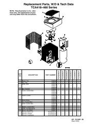
Gas Conversion to Propane Gas Kit for Part
Gas Conversion to Propane Gas Kit for Part
Gas Conversion to Propane Gas Kit for Part

You also want an ePaper? Increase the reach of your titles
YUMPU automatically turns print PDFs into web optimized ePapers that Google loves.
PGS***K040F, GPSM**K040<br />
PGS***K060F, GPSM**K060<br />
PGS***K080F, GPSM**K080<br />
PGS***K100F, GPSM**K100<br />
PGS***K120F, GPSM**K120<br />
PGS***K140F, GPSM**K140<br />
PGF3**040<br />
PGF3**060<br />
PGF3**080<br />
PGF3**100<br />
PGF3**120<br />
PGF3**140<br />
Table 1<br />
Model Number Orifice Drill #<br />
PGAA, PGMD (All Sizes)<br />
PGAD, PGME (All Sizes)<br />
PGX3, PDX3 (All Sizes)<br />
PGC***K040F, GPCM**K040<br />
PGC***K060F, GPCM**K060<br />
PGC***K080F, GPCM**K080<br />
PGC***K100F, GPCM**K100<br />
PGC***K120F, GPCM**K120<br />
PGC***K140F, GPCM**K140<br />
PGF***K040F, GPFM**K040<br />
PGF***K060F, GPFM**K060<br />
PGF***K080F, GPFM**K080<br />
PGF***K100F, GPFM**K100<br />
PGF***K120F, GPFM**K120<br />
PGF***K140F, GPFM**K140<br />
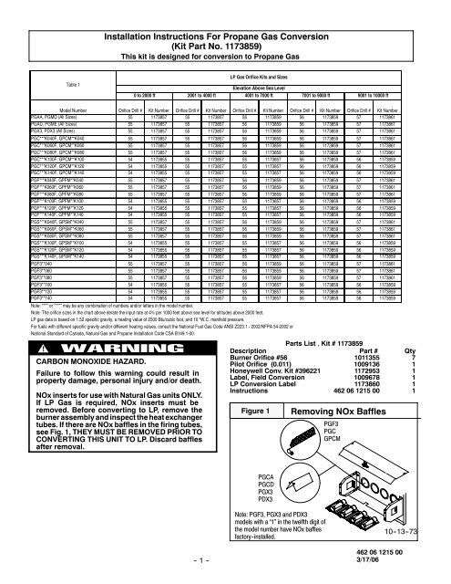
Installation Instructions For <strong>Propane</strong> <strong>Gas</strong> <strong>Conversion</strong><br />
(<strong>Kit</strong> <strong>Part</strong> No. 1173859)<br />
This kit is designed <strong>for</strong> conversion <strong>to</strong> <strong>Propane</strong> <strong>Gas</strong><br />
<strong>Kit</strong> Number Orifice Drill # <strong>Kit</strong> Number Orifice Drill # <strong>Kit</strong> Number Orifice Drill # <strong>Kit</strong> Number Orifice Drill # <strong>Kit</strong> Number<br />
55 1173857 55 1173857 56 1173859 56 1173859 57 1173861<br />
55 1173857 55 1173857 56 1173859 56 1173859 57 1173861<br />
55 1173857 55 1173857 56 1173859 56 1173859 57 1173861<br />
55 1173857 55 1173857 56 1173859 56 1173859 57 1173861<br />
55 1173857 55 1173857 56 1173859 56 1173859 57 1173861<br />
55 1173857 55 1173857 56 1173859 56 1173859 57 1173861<br />
54 1173855 55 1173857 55 1173857 56 1173859 56 1173859<br />
54 1173855 55 1173857 55 1173857 56 1173859 56 1173859<br />
54 1173855 55 1173857 55 1173857 56 1173859 56 1173859<br />
55 1173857 55 1173857 56 1173859 56 1173859 57 1173861<br />
55 1173857 55 1173857 56 1173859 56 1173859 57 1173861<br />
55 1173857 55 1173857 56 1173859 56 1173859 57 1173861<br />
54 1173855 55 1173857 55 1173857 56 1173859 56 1173859<br />
54 1173855 55 1173857 55 1173857 56 1173859 56 1173859<br />
54 1173855 55 1173857 55 1173857 56 1173859 56 1173859<br />
55 1173857 55 1173857 56 1173859 56 1173859 57 1173861<br />
55 1173857 55 1173857 56 1173859 56 1173859 57 1173861<br />
55 1173857 55 1173857 56 1173859 56 1173859 57 1173861<br />
54 1173855 55 1173857 55 1173857 56 1173859 56 1173859<br />
54 1173855 55 1173857 55 1173857 56 1173859 56 1173859<br />
54 1173855 55 1173857 55 1173857 56 1173859 56 1173859<br />
55 1173857 55 1173857 56 1173859 56 1173859 57 1173861<br />
55 1173857 55 1173857 56 1173859 56 1173859 57 1173861<br />
55 1173857 55 1173857 56 1173859 56 1173859 57 1173861<br />
54 1173855 55 1173857 55 1173857 56 1173859 56 1173859<br />
54 1173855 55 1173857 55 1173857 56 1173859 56 1173859<br />
54 1173855 55 1173857 55 1173857 56 1173859 56 1173859<br />
Note: "**" or "***" may be any combination of numbers and/or letters in the model number.<br />
Note: The orifice sizes in the chart above derate the input rate at 4% per 1000 feet above sea level <strong>for</strong> altitudes above 2000 feet.<br />
LP gas data is based on 1.52 specific gravity, a heating value of 2500 Btu/cubic foot, and 10 "W.C. manifold pressure.<br />
For fuels with different specific gravity and/or different heating values, consult the National Fuel <strong>Gas</strong> Code ANSI Z223.1 - 2002/NFPA 54-2002 or<br />
National Standard of Canada, Natural <strong>Gas</strong> and <strong>Propane</strong> Installation Code CSA B149.1-00.<br />
!<br />
CARBON MONOXIDE HAZARD.<br />
Failure <strong>to</strong> follow this warning could result in<br />
property damage, personal injury and/or death.<br />
NOx inserts <strong>for</strong> use with Natural <strong>Gas</strong> units ONLY.<br />
If LP <strong>Gas</strong> is required, NOx inserts must be<br />
removed. Be<strong>for</strong>e converting <strong>to</strong> LP, remove the<br />
burner assembly and inspect the heat exchanger<br />
tubes. If there are NOx baffles in the firing tubes,<br />
see Fig. 1, THEY MUST BE REMOVED PRIOR TO<br />
CONVERTING THIS UNIT TO LP. Discard baffles<br />
after removal.<br />
-- 1 --<br />
LP <strong>Gas</strong> Orifice <strong>Kit</strong>s and Sizes<br />
0 <strong>to</strong> 2000 ft 2001 <strong>to</strong> 4000 ft<br />
Elevation Above Sea Level<br />
4001 <strong>to</strong> 7000 ft 7001 <strong>to</strong> 9000 ft<br />
9001 <strong>to</strong> 10000 ft<br />
<strong>Part</strong>s List , <strong>Kit</strong> # 1173859<br />
Description <strong>Part</strong> # Qty<br />
Burner Orifice #56 1011355 7<br />
Pilot Orifice (0.011) 1009136 1<br />
Honeywell Conv. <strong>Kit</strong> #396221 1172953 1<br />
Label, Field <strong>Conversion</strong> 1009678 1<br />
LP <strong>Conversion</strong> Label 1173860 1<br />
Instructions 462 06 1215 00 1<br />
Figure 1 Removing NOx Baffles<br />
PGCA<br />
PGCD<br />
PGX3<br />
PDX3<br />
Note: PGF3, PGX3 and PDX3<br />
models with a “1” in the twelfth digit of<br />
the model number have NOx baffles<br />
fac<strong>to</strong>ry -installed.<br />
PGF3<br />
PGC<br />
GPCM<br />
10--13--73<br />
462 06 1215 00<br />
3/17/06
SAFETY REQUIREMENTS<br />
Recognize safety in<strong>for</strong>mation. This is the safety--alert symbol !<br />
.<br />
When you see this symbol in instruction manuals be alert <strong>to</strong> the<br />
potential <strong>for</strong> personal injury.<br />
Understand the signal words DANGER,WARNING, or CAUTION.<br />
These words are used with the safety--alert symbol. DANGER<br />
identifies the most serious hazards, those that will result in severe<br />
personal injury or death. WARNING signifies a hazard that could<br />
result in personal injury or death. CAUTION is used <strong>to</strong> identify<br />
unsafe practices that may result in minor personal injury or product<br />
and property damage. NOTE is used <strong>to</strong> highlight suggestions that<br />
will result in enhanced installation, reliability, or operation.<br />
Installing and servicing heating equipment can be hazardous due <strong>to</strong><br />
gas and electrical components. Only trained and qualified<br />
personnel should install, repair, or service heating equipment.<br />
Untrained service personnel can per<strong>for</strong>m basic maintenance<br />
functions such as cleaning and replacing air filters. All other<br />
operations must be per<strong>for</strong>med by trained service personnel. When<br />
working on heating equipment, observe precautions in the<br />
literature, on tags, and on labels attached <strong>to</strong> or shipped with the<br />
appliance and other safety precautions that may apply.<br />
Follow all safety codes. In the United States, follow all safety codes<br />
including the National Fuel <strong>Gas</strong> Code (NFGC) ANSI<br />
Z223.1--2006/NFPA 54--2006. In Canada, refer <strong>to</strong> the of the<br />
National Standard of Canada Natural <strong>Gas</strong> and <strong>Propane</strong> Installation<br />
Code (NSCNGPIC) CSA B149.1--05. Wear safety glasses and<br />
work gloves. Have fire extinguisher available during start--up and<br />
adjustment procedures and service calls.<br />
These instructions cover minimum requirements and con<strong>for</strong>m <strong>to</strong><br />
existing national standards and safety codes. In some instances,<br />
these instructions exceed certain local codes and ordinances,<br />
especially those that may not have kept up with changing residential<br />
construction practices. We require these instructions as a minimum<br />
<strong>for</strong> a safe installation.<br />
Important In<strong>for</strong>mation<br />
This kit is <strong>for</strong> conversion of furnaces equipped with Honeywell<br />
VR8200, VR8205S, SV9500, SV9501 or VR8204M gas valves<br />
certified <strong>for</strong> use with Natural <strong>Gas</strong> (and so marked) <strong>to</strong> units<br />
functionally the same as the certified furnace <strong>for</strong> use with <strong>Propane</strong><br />
<strong>Gas</strong>. A gas valve conversion kit must be installed and main burner<br />
orifices and pilot burner orifice must be replaced with orifices in this<br />
kit.<br />
The orifices provided in this kit are stamped <strong>to</strong> indicate the size<br />
(twist drill number) and are sized <strong>for</strong> commercially pure propane gas<br />
ONLY. Do NOT use them with butane or a mixture of butane and<br />
propane. The parts list specifies the size orifices supplied in the kit.<br />
Compare the size marking on the orifices with the sizes as listed in<br />
the parts list. Make sure you have the correct main burner orifices.<br />
Refer <strong>to</strong> Table 1 <strong>for</strong> proper orifice size <strong>for</strong> specific model number,<br />
input capacity, and installation altitude.<br />
Extreme care is used <strong>to</strong> assure that this kit contains the proper<br />
orifices. Oversized orifices could result in hazardous<br />
conditions, especially if the venting is inadequate. For that<br />
reason, we recommend that the installer check the size of the orifice<br />
with a new twist drill of the correct size. This procedure assures that<br />
the orifices provided are the correct size.<br />
D Shut off gas supply <strong>to</strong> furnace at manual shut--off valve be<strong>for</strong>e<br />
starting installation.<br />
-- 2 --<br />
!<br />
EXPLOSION HAZARD<br />
Failure <strong>to</strong> follow this warning could result in<br />
personal injury, death and/or property damage.<br />
If unit is still running, allow 3 minutes after gas<br />
shut off be<strong>for</strong>e turning off power, Shut Off electric<br />
power at unit disconnect and service panel.<br />
D Disconnect electric power supply <strong>to</strong> the furnace be<strong>for</strong>e starting<br />
installation.<br />
D Check <strong>for</strong> gas leaks after installation of kit and be<strong>for</strong>e attempting<br />
<strong>to</strong> start furnace.<br />
D Locate the LP <strong>Gas</strong> <strong>Conversion</strong> Label next <strong>to</strong> the furnace rating<br />
plate.<br />
D Fill out and attach the Field <strong>Conversion</strong> Label <strong>to</strong> the front exterior<br />
of the furnace.<br />
!<br />
FIRE, EXPLOSION, CARBON MONOXIDE<br />
POISONING HAZARD.<br />
Failure <strong>to</strong> follow these instructions exactly could<br />
result in personal injury, death and/or property<br />
damage.<br />
This conversion kit shall be installed by a<br />
qualified service agency in accordance with the<br />
manufacturer’s instructions and all applicable<br />
codes and requirements of the authority having<br />
jurisdiction. If the in<strong>for</strong>mation in these<br />
instructions is not followed exactly, a fire, an<br />
explosion or production of carbon monoxide may<br />
result causing property damage, personal injury<br />
or loss of life. The qualified service agency is<br />
responsible <strong>for</strong> the proper installation of this kit.<br />
The installation is not proper and complete until<br />
the operation of the converted appliance is<br />
checked as specified in the manufacturer’s<br />
instructions supplied with the kit.<br />
<strong>Gas</strong> Pressure<br />
D Refer <strong>to</strong> the furnace rating plate <strong>for</strong> the approved gas input<br />
rating.<br />
D <strong>Gas</strong> input <strong>to</strong> burners MUST NOT exceed the rated input<br />
shownonratingplate.<br />
D Do NOT allow minimum gas supply pressure <strong>to</strong> vary downward.<br />
Doing so will decrease input <strong>to</strong> furnace. Refer <strong>to</strong> Table<br />
2 <strong>for</strong> gas supply and manifold pressures.<br />
Table 2<br />
<strong>Gas</strong> Pressures<br />
<strong>Gas</strong> Supply Pressure Manifold<br />
Type Recommended Max. Min. Pressure<br />
LP<br />
11″<br />
(2.7kPa)<br />
14″<br />
(3.5kPa)<br />
11″<br />
(2.7kPa)<br />
10″<br />
(2.5kPa)<br />
462 06 1215 00<br />
3/17/06
Installation<br />
!<br />
ELECTRIC SHOCK HAZARD/FIRE AND/OR<br />
EXPLOSION HAZARD.<br />
Failure <strong>to</strong> follow this warning could result in<br />
equipment damage, personal injury, death and/or<br />
property damage.<br />
The gas supply shall be shut OFF prior <strong>to</strong><br />
disconnecting the electrical power, be<strong>for</strong>e<br />
proceeding with the conversion.<br />
Turn OFF electric power supply at disconnect switch<br />
or service panel be<strong>for</strong>e starting installation.<br />
Disassembly<br />
Refer <strong>to</strong> Figure 2 and the following steps.<br />
Figure 2<br />
Disassembly<br />
1. After shutting off gas supply and electric power <strong>to</strong> the unit remove<br />
the access door, exposing gas valve and burner<br />
compartment.<br />
2. Disconnect gas line from gas valve so manifold assembly can<br />
be removed.<br />
3. Disconnect wiring at gas valve. Be sure <strong>to</strong> note the proper<br />
location of any and all electrical wiring disconnected.<br />
4. Remove the pilot supply line from the gas valve.<br />
5. Remove the four (4) screws holding the manifold and gas<br />
valve <strong>to</strong> the manifold supports. Do Not discard any screws.<br />
6. Carefully remove the manifold assembly.<br />
7. If unit has v--shaped NOx baffles installed in firing tubes, they<br />
must be removed. Some baffles may be attached by screws.<br />
Replace screws after removing NOx baffles (figure 3).<br />
!<br />
CARBON MONOXIDE HAZARD.<br />
Failure <strong>to</strong> follow this warning could result in<br />
personal injury, death and/or property damage.<br />
NOx baffles <strong>for</strong> use with Natural <strong>Gas</strong> units ONLY. If<br />
LP <strong>Gas</strong> is required, NOx inserts must be removed.<br />
-- 3 --<br />
Figure 3<br />
or<br />
Removing NOx Baffles<br />
Changing Main Burner Orifices<br />
1. Remove the Natural gas (brass) burner orifices from the<br />
manifold assembly using a box end wrench or socket wrench,<br />
and replace them with the (silver) orifices furnished in the<br />
conversion kit (Figure 4).<br />
Figure 4<br />
Changing Orifices<br />
2. Tighten the orifices so they are 1 3 / 16″ from the face of the orifice<br />
<strong>to</strong> the backside of the manifold (See Figure 5).Make<br />
sure orifice is installed straight so that it <strong>for</strong>ms a right angle<br />
(90°) <strong>to</strong> the manifold.<br />
Figure 5<br />
Orifices Clearances<br />
Measure 1 3 / 16″ from face of orifice<br />
<strong>to</strong> the back side of the<br />
manifold.<br />
Changing Pilot Burner Orifice (All models<br />
except PGF3, PGX3, and PDX3.)<br />
1. Disconnect the pilot supply line from the pilot burner.<br />
2. Remove pilot orifice from pilot burner. Replace<br />
with propane gas orifice stamped BBR11 which is<br />
462 06 1215 00<br />
3/17/06
provided in kit. See Figure 6.<br />
3.. Reconnect the pilot tubing securely <strong>to</strong> the pilot burner.<br />
4. Verify proper relationship of pilot burner assembly per Figure<br />
7 prior <strong>to</strong> completing the conversion.<br />
Figure 6<br />
Orifice<br />
with<br />
Red Dot<br />
Changing Pilot Orifice<br />
Figure 7 Burner Pilot Assembly<br />
<strong>Gas</strong> Valve <strong>Conversion</strong><br />
<strong>Conversion</strong> of Honeywell VR8200, VR8205S, SV9500, SV9501<br />
and VR8204M <strong>Gas</strong> Valves using <strong>Propane</strong> <strong>Gas</strong> <strong>Conversion</strong> <strong>Kit</strong><br />
#396621.<br />
1. Remove the regula<strong>to</strong>r cap screw and pressure regula<strong>to</strong>r adjusting<br />
screw. (See Figure 11.)<br />
Figure 8<br />
Inlet Pressure<br />
Tap (Hidden)<br />
INLET<br />
Typical <strong>Gas</strong> Valve Honeywell<br />
SV9500<br />
OFF<br />
WARNING<br />
Explosion Hazard.<br />
Serious injory or death<br />
can result.<br />
Read instructions be<strong>for</strong>e<br />
operating valve.<br />
Never use <strong>to</strong>ols <strong>to</strong><br />
operate valve. Do not<br />
disassemble valve. call a<br />
qualified service technician<br />
if the appliance does not<br />
function properly.<br />
ON<br />
IGNITER<br />
Pilot Adjustment<br />
Outlet Pressure Tap<br />
Connect manometer here <strong>to</strong> check outlet<br />
pressure. Must be adjusted per Table 2.<br />
Honeywell<br />
CONTROL<br />
25-50-06<br />
OUTLET<br />
Wiring<br />
Terminals<br />
Pilot<br />
Outlet<br />
-- 4 --<br />
Figure 9<br />
Inlet Pressure<br />
Tap (Hidden)<br />
INLET<br />
Pilot<br />
Adjustment<br />
Figure 10<br />
Typical <strong>Gas</strong> Valve Honeywell<br />
SV9501<br />
Outlet Pressure Tap<br />
Connect manometer here <strong>to</strong><br />
check outlet pressure. Must be<br />
adjusted per Table 2.<br />
Regula<strong>to</strong>r Adjustment<br />
Under Cap<br />
INLET<br />
Inlet<br />
Pressure<br />
Tap 1 / 8 NPT<br />
V T<br />
Wiring Terminals<br />
OUTLET<br />
25--22--25<br />
Typical <strong>Gas</strong> Valve Honeywell<br />
VR8205S<br />
HONEYWELL<br />
OFF<br />
ON<br />
25--24--98a<br />
Pilot<br />
Outlet<br />
462 06 1215 00<br />
3/17/06<br />
Outlet<br />
Pressure<br />
Tap<br />
1 /8 NPT<br />
OUTLET<br />
2. Remove the existing regula<strong>to</strong>r spring from the regula<strong>to</strong>r<br />
housing.<br />
3. Insert the replacement spring (red color) contained in this kit<br />
in<strong>to</strong> regula<strong>to</strong>r housing.
Figure 11<br />
PRESSURE<br />
REGULATOR<br />
HOUSING<br />
Typical Honeywell<br />
Regula<strong>to</strong>r Assembly<br />
LP Natural<br />
<strong>Gas</strong> <strong>Gas</strong><br />
Cap Screw Black Silver<br />
Pressure White White<br />
Regula<strong>to</strong>r<br />
Adjusting<br />
Screw<br />
Stainless<br />
Spring Red Steel<br />
4. Install the pressure regula<strong>to</strong>r adjusting screw and give it eight<br />
(8) full turns. This will set the manifold pressure close <strong>to</strong> required<br />
setting <strong>for</strong> normal operation.<br />
5. Replace the regula<strong>to</strong>r cap screw.<br />
6. Attach gas valve conversion label (found in Honeywell conversion<br />
kit) <strong>to</strong> gas valve.<br />
Reassembly<br />
Reassemble all parts in reverse order as removed. Attach LP <strong>Gas</strong><br />
<strong>Conversion</strong> Label next <strong>to</strong> the unit rating plate. Fill out and attach the<br />
Field conversion Label <strong>to</strong> the front exterior of the furnace.<br />
D Manifold Assembly -- Be sure <strong>to</strong> engage the main burner orifices<br />
in the proper openings in the burners.<br />
D Testing <strong>for</strong> leaks -- After reassembly, turn the gas on and<br />
check all joints <strong>for</strong> gas leaks using a soapy solution. All leaks<br />
must be repaired immediately.<br />
Start -up and Check -out<br />
1. Remove the plug from the Inlet Pressure Tap on gas valve<br />
and install a manometer. (See Figure 8, Figure 9, Figure10<br />
& Figure 11)<br />
2. Open manual gas line valve <strong>to</strong> unit. Check <strong>for</strong> gas leaks and<br />
correct as necessary. Check supply pressure. Refer <strong>to</strong> Table<br />
2 <strong>for</strong> proper supply pressure values. If not within these limitations<br />
DO NOT OPERATE UNIT, contact gas supplier.<br />
3. Close manual gas line valve <strong>to</strong> unit, remove manometer and<br />
replace inlet pressure tap plug.<br />
<strong>Gas</strong> Valve Adjustment<br />
4. With the gas valve knob in the OFF position, remove the pressure<br />
tap plug from the outlet end of the valve, and connect a<br />
“U” tube manometer <strong>to</strong> the pressure port. (See Figure 8,<br />
Figure 9, Figure 10 & Figure 11).<br />
5. Turn the gas valve knob <strong>to</strong> the ON position and res<strong>to</strong>re electrical<br />
power <strong>to</strong> unit. Cycle the main burner on and off several<br />
times <strong>to</strong> stabilize the pressure regula<strong>to</strong>r diaphragm. This<br />
MUST be done be<strong>for</strong>e an accurate pressure reading can be<br />
obtained.<br />
-- 5 --<br />
6. With the main burner on, read the pressure gauge. Manifold<br />
pressure should be adjusted <strong>to</strong> values from Table 2. Turn<br />
pressure regula<strong>to</strong>r adjusting screw clockwise <strong>to</strong> increase or<br />
counterclockwise <strong>to</strong> decrease manifold pressure. Burner Input<br />
must not exceed nameplate rating. Refer <strong>to</strong> Section<br />
“Heating Input Rate Check”.<br />
7. Turn gas valve <strong>to</strong> OFF. Remove the pressure gauge and replace<br />
the pressure tap plug and pressure regula<strong>to</strong>r cap<br />
screw.<br />
8. With gas valve on, observe furnace through two or more complete<br />
cycles <strong>to</strong> be sure all controls are operating.<br />
!<br />
FIRE AND/OR EXPLOSION HAZARD<br />
Failure <strong>to</strong> follow this warning could result in personal<br />
injury, death, and/or property damage.<br />
Do NOT attempt <strong>to</strong> light the burner with a match or<br />
flame of any kind.<br />
Heating Input Rate Check<br />
The gas input <strong>to</strong> the unit is determined by measuring the<br />
gas flow at the meter. Measuring gas flow at the meter is<br />
recommended <strong>for</strong> all units. To measure the heating<br />
input, per<strong>for</strong>m the following steps:<br />
1. Turn off all other gas appliances that use the same<br />
meter.<br />
2. Turn off gas supply <strong>to</strong> unit and attach manifold pressure<br />
gauge as instructed in the ”<strong>Gas</strong> Valve Adjustment”<br />
section.<br />
3. With gas ON <strong>to</strong> the unit and the unit operating, record<br />
the number of seconds <strong>for</strong> the gas meter dial <strong>to</strong> make<br />
one revolution.<br />
4. Divide number of seconds in Step 3 in<strong>to</strong> 3600 (number<br />
of seconds in 1 hour).<br />
5. Multiply result of Step 4 by the number of cubic feet<br />
shown <strong>for</strong> one revolution of the meter dial <strong>to</strong> obtain the<br />
cubic feet of gas flow per hour.<br />
6. Multiply result of Step 5 by Btu heating value of gas <strong>to</strong><br />
obtain <strong>to</strong>tal measured input in Btu/hr. Compare this<br />
input rate with the Required Input Rate <strong>for</strong> the<br />
installation altitude, as shown in Table 3. Consult with<br />
local gas supplier if the heating value of gas is not<br />
known.<br />
Example: Assume the installation of a PGF348120 at an<br />
altitude of 3500 feet. Assume that the size of the meter dial is<br />
1 cu. ft., one revolution takes 91 seconds, and the heating<br />
value of propane gas is 2500 Btu/ft3. Proceed as follows:<br />
1. 91 sec. To complete 1 revolution<br />
2. 3600/91 = 39.6<br />
3. 39.6 x 1 = 39.6<br />
4. 39.6 x 2500 = 98,901 Btu/hr<br />
For this example, the nameplate input is 100,800 Btu/hr, so<br />
only a minor change in manifold pressure is required. In no<br />
case should the final manifold pressure vary more than<br />
+-- .3 ”water column from the values in Table 2. Never exceed<br />
the required input rate (Table 3).<br />
462 06 1215 00<br />
3/17/06
Required Input Rate <strong>for</strong> PGF3, PGF, PGS, PGS, GPFM, GPCM, and GPSM Models<br />
Required Input Rate of Furnace Converted <strong>to</strong> <strong>Propane</strong> <strong>Gas</strong> (Btu/hr)<br />
Heating Model<br />
Elevation Above Sea Level (feet)<br />
Size 0-2000 2001-3000 3001-4000 4001-5000 5001-6000 6001-7000 7001-8000 8001-9000 9001-10000<br />
"040" 40,000 35200 33600 32000 30400 28800 27200 25600 24000<br />
"060" 60,000 52800 50400 48000 45600 43200 40800 38400 36000<br />
"080" 80,000 70400 67200 64000 60800 57600 54400 51200 48000<br />
"100" 94,000 82720 78960 75200 71440 67680 63920 60160 56400<br />
"120" 117,000 102960 98280 93600 88920 84240 79560 74880 70200<br />
"140" 140,000 123200 117600 112000 106400 100800 95200 89600 84000<br />
1<br />
Table 3<br />
1 Note:<br />
For PGF3 models, heating model size is indicated by the numbers in the 5 th , 6 th , and 7 th characters in the model number.<br />
For PGF, PGC, PGS models, heating model size is indicated by the numbers in the 8 th , 9 th , and 10 th characters in the model number.<br />
For GPFM, GPCM, and GPSM models, heating model size is indicated by the numbers in the 8 th , 9 th , and 10 th characters in the model number.<br />
Required Input Rate <strong>for</strong> PGX3, PDX3, PGAA, PGAD, PGCA, PGCD, PGMD, and PGME Models<br />
Required Input Rate of Furnace Converted <strong>to</strong> <strong>Propane</strong> <strong>Gas</strong> (Btu/hr)<br />
Heating Model<br />
Elevation Above Sea Level (feet)<br />
Size 0-2000 2001-3000 3001-4000 4001-5000 5001-6000 6001-7000 7001-8000 8001-9000 9001-10000<br />
"040" or "B" 40,000 35200 33600 32000 30400 28800 27200 25600 24000<br />
"060" or "C" 60,000 52800 50400 48000 45600 43200 40800 38400 36000<br />
"080" or "D" 80,000 70400 67200 64000 60800 57600 54400 51200 48000<br />
"100" or "E" 100,000 88000 84000 80000 76000 72000 68000 64000 60000<br />
"120" or "F" 120,000 105600 100800 96000 91200 86400 81600 76800 72000<br />
"140" or "G" 140,000 123200 117600 112000 106400 100800 95200 89600 84000<br />
1<br />
1 Note:<br />
For PGX3 and PDX3 models, heating model size is indicated by the numbers in the 5 th , 6 th , and 7 th characters in the model number.<br />
For PGAA, PGAD, PGCA, and PGCD models, heating model size is indicated by the letter in the 7 th character in the model number.<br />
For PGMD and PGME models, heating model size is indicated by the letter in the 7 th character in the model number.<br />
Pilot Burner Flame Check (All models<br />
except PGF3, PGX3, and PDX3).<br />
Adjust flames so they surround 3 / 8″ (9 mm) <strong>to</strong> 1 / 2″ (13 mm) of the<br />
thermocouple/sensor tip (See Figure 12).<br />
1. Remove the cap from the pilot adjusting screw (See Figures<br />
8&9).<br />
2. Turn pilot adjusting screw counterclockwise <strong>to</strong> increase,<br />
clockwise <strong>to</strong> decrease.<br />
3. Replace the cap on the pilot adjusting screw.<br />
Figure 12<br />
Proper Flame<br />
Adjustment<br />
Pilot Burner (HSP)<br />
10 -- 11 -- 65<br />
Sensor Tip<br />
Hot Surface<br />
Igniter<br />
-- 6 --<br />
Main Burner Flame Check<br />
Check <strong>for</strong> the following:<br />
D Stable and blue flames (See Figure 13). Dust may cause<br />
orange tips or wisps of yellow, but flames MUST NOT have<br />
solid, yellow tips.<br />
D Flames extending directly from burner in<strong>to</strong> heat exchanger.<br />
D Flames DO NOT <strong>to</strong>uch sides of heat exchanger<br />
Figure 13<br />
Main Burner<br />
BLUE FLAME<br />
25--00--07a<br />
462 06 1215 00<br />
3/17/06