MX420 Navigation System - Polaris-as.dk
MX420 Navigation System - Polaris-as.dk
MX420 Navigation System - Polaris-as.dk

Create successful ePaper yourself
Turn your PDF publications into a flip-book with our unique Google optimized e-Paper software.
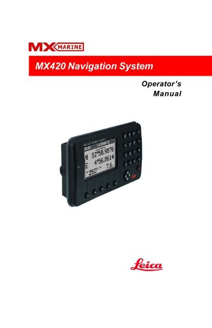
<strong>MX420</strong> <strong>Navigation</strong> <strong>System</strong><br />
oOperator’s<br />
Manual
TIMES.<br />
Product Information<br />
<strong>MX420</strong> Operator’s Manual<br />
<strong>MX420</strong>/2 GPS/DGPS<br />
<strong>MX420</strong>/8 GPS/DGPS<br />
<strong>MX420</strong>/BR<br />
<strong>MX420</strong>/BRIM<br />
<strong>MX420</strong>/MKD<br />
<strong>MX420</strong>/AIS DGPS<br />
IMPORTANT NOTICE!!<br />
THE <strong>MX420</strong> IS AN AID TO NAVIGATION ONLY. UNDER NO CIRCUM-<br />
STANCES SHOULD IT BE USED IN LIEU OF AUTHORIZED GOVERN-<br />
MENT CHARTS. ITS ACCURACY CAN BE AFFECTED BY MANY FAC-<br />
TORS SUCH AS EQUIPMENT DEFECTS, ENVIRONMENTAL CONDI-<br />
TIONS, OR IMPROPER OPERATION. THE USER IS RESPONSIBLE<br />
FOR SAFE NAVIGATION OF THE VESSEL. THIS INCLUDES CON-<br />
SULTING AUTHORIZED GOVERNMENT CHARTS AND EXERCISING<br />
COMMON PRUDENCE AND NAVIGATIONAL JUDGEMENT AT ALL<br />
The model and serial number of your instrument are given on<br />
the instrument. Enter the model and serial number in the<br />
spaces provided below. Always refer to this information when<br />
you contact your dealer.<br />
<strong>MX420</strong> CDU Serial No.:_________________<br />
MX421 GPS Antenna S/N: _______________<br />
MX525 GPS Sensor S/N _________________<br />
© Copyright March, 2003<br />
Doc. P/N 3508 102 70040
Symbols Used In This Manual<br />
!<br />
!<br />
!<br />
Danger<br />
Indicates an imminently hazardous situation which, if not avoided,<br />
will result in death or serious injury.<br />
Warning<br />
Indicates a potentially hazardous situation which, if not avoided,<br />
could result in death or serious injury.<br />
Caution<br />
Indicates a potentially hazardous situation which, if not avoided, may<br />
result in minor or moderate injury and/or appreciable material, financial<br />
and environmental damage. This symbol is also used to alert against<br />
unsafe practices.<br />
Important paragraphs which must be adhered to in practice, <strong>as</strong> they<br />
enable the product to be used in a technically correct and efficient<br />
manner.<br />
This manual contains important safety directions <strong>as</strong> well <strong>as</strong> instructions<br />
for setting up the instrument and operating it. Read carefully<br />
through the Operator’s Manual, Options Manual, and Installation<br />
& Service Manual before you switch on the instrument.
Scope Of This Manual<br />
This manual reflects the software capabilities in version 2.0 software.<br />
We have attempted to take care and develop manuals which provide<br />
in-depth information. Where possible, we have attempted not only to<br />
describe what you see on the screen, but how to understand and use<br />
it <strong>as</strong> well. Obviously, we can’t teach you how to navigate, but we can<br />
help make your work more thorough and enjoyable. Throughout the<br />
manual, you will find helpful hints about the interaction of various<br />
functions. In a piece of equipment that h<strong>as</strong> the many capabilities of<br />
this receiver, important details can sometimes become obscured in one<br />
or two lines of text. In our effort to ensure you get the most out of this<br />
documentation, and to protect against important details becoming lost,<br />
don’t be surprised if you see the same or similar information more than<br />
once.<br />
This manual is organized by describing first the various <strong>MX420</strong> models<br />
covered in this book. Then the special front panel features including<br />
the traffic light indicator. The sections that follow detail each primary<br />
function <strong>as</strong> it is presented on the front panel (i.e. NAV, RTE, WPT,<br />
PLOT, ...CFG). The appedixes describe important details about special<br />
functions.<br />
Appendix-A is a special section describing the AIS displays and setups<br />
of the <strong>MX420</strong>/AIS model.<br />
We hope you find the manual enjoyable and informative reading. As<br />
always, we welcome your comments on improving our products or<br />
manuals. We wouldn’t mind if you wrote to tell us that we did the job<br />
right the first time either. You can find a Reader Comment Card at the<br />
back of the manual.<br />
Related Documents<br />
MX 420 Installation & Service Manual (P/N 3508 102 70060)<br />
MX 420 Quick Reference Guide (P/N 3508 102 70050)<br />
<strong>MX420</strong>/AIS Reference Card (P/N 725626) (for AIS models only)
How To Contact Us?<br />
Contact your local MX Marine dealer for:<br />
• Installation, Service, & Technical Support<br />
• Sales of Accessories<br />
• Hardware and Software Upgrades<br />
Unlike many other consumer electronics industries which only<br />
sell consumer electronic devices, your marine dealer is often your<br />
best advisor for installation and service of your new GPS receiver.<br />
MX Marine strongly encourages you to utilize the knowledge and<br />
experience of your sales and service dealer.<br />
Should you need to contact us directly for new sales, upgrades,<br />
repair service, or technical support, we can be reached at the<br />
following:<br />
International:<br />
MX Marine (USA)<br />
23868 Hawthorne Blvd., Suite 200<br />
Torrance, California 90505<br />
USA<br />
+1-310-791-8213 Telephone (International)<br />
+1-310-791-6108 Fax<br />
In Europe:<br />
MX Marine (Denmark)<br />
Høkær12A<br />
DK-2730 Herlev<br />
Denmark<br />
+45-44-54-03-00 Telephone<br />
+45-44-54-03-30 Fax<br />
+45-44-54-03-30 Sales Fax<br />
Internet:<br />
www.mx-marine.com
Table of Contents Operator’s Manual<br />
Table of Contents<br />
About GPS <strong>Navigation</strong> ................................................................................ 1<br />
Special Notes ................................................................................. 2<br />
GPS ........................................................................................ 2<br />
DGPS ...................................................................................... 2<br />
Charts and <strong>Navigation</strong>al Aids ................................................... 2<br />
Functional Description ................................................................................. 3<br />
<strong>MX420</strong> Configurations .................................................................... 3<br />
<strong>MX420</strong>/2 GPS .......................................................................... 3<br />
<strong>MX420</strong>/2 DGPS ....................................................................... 3<br />
<strong>MX420</strong>/8 GPS .......................................................................... 3<br />
<strong>MX420</strong>/8 DGPS ....................................................................... 3<br />
<strong>MX420</strong>/BR ............................................................................... 4<br />
<strong>MX420</strong>/BRIM (Dual Control Integrity Monitor)............................ 4<br />
<strong>MX420</strong>/AIS B<strong>as</strong>ic (Automatic Identification <strong>System</strong>-B<strong>as</strong>ic) ...... 5<br />
<strong>MX420</strong>/AIS (AIS & <strong>Navigation</strong> <strong>System</strong>)................................... 5<br />
DGPS Beacon <strong>System</strong>................................................................................ 6<br />
Keypad & Display Description ..................................................................... 7<br />
Differential GPS Traffic Light Operation: ......................................... 8<br />
Red Fl<strong>as</strong>hing ........................................................................... 8<br />
Red/Yellow Solid ...................................................................... 8<br />
Red Solid ................................................................................. 8<br />
Yellow/Green Solid ................................................................... 8<br />
Yellow Solid ............................................................................. 9<br />
Green Solid .............................................................................. 9<br />
GPS Traffic Light Operation: .......................................................... 9<br />
Red Fl<strong>as</strong>hing ........................................................................... 9<br />
Red/Yellow Solid ...................................................................... 9<br />
Red Solid ................................................................................. 9<br />
Yellow Solid ........................................................................... 10<br />
Green Solid ............................................................................ 10<br />
The Display: ................................................................................. 10<br />
The Softkeys: ...................................................................... 11<br />
The Function Keys: ...................................................................... 11<br />
Version 2.0 i
Operator Manual Table of Contents<br />
Mark Position .............................................................. 11<br />
GOTO .......................................................................... 12<br />
LIGHT .......................................................................... 12<br />
POWER ON/OFF ........................................................ 12<br />
MAN OVER BOARD (MOB) ......................................... 13<br />
E E (EDIT) ...................................................................... 14<br />
C C (CLEAR) ................................................................... 14<br />
1<br />
NAV<br />
ABC<br />
AIS<br />
9<br />
YZ<br />
CURSOR ..................................................................... 14<br />
FUNCTION .................................................................. 14<br />
Automatic Identification <strong>System</strong> (AIS) ......................... 16<br />
Navigate .................................................................................................... 17<br />
Dead Reckoning ........................................................................... 18<br />
NAV1 - The Panorama Screen ..................................................... 18<br />
NAV2 - B<strong>as</strong>ic Steering Information ............................................... 21<br />
NAV 3 - Expanded <strong>Navigation</strong> Information .................................... 22<br />
NAV4 - Sensor Input <strong>Navigation</strong> ................................................... 23<br />
Route ........................................................................................................ 27<br />
RTE1 - The Active Route ............................................................. 28<br />
Creating a Route Using the GOTO Key: ................................. 29<br />
Er<strong>as</strong>ing an Existing Route ...................................................... 32<br />
Creating a Multi-Waypoint Active Route ................................. 33<br />
Insert By Number................................................................... 34<br />
Choose in Bank ..................................................................... 34<br />
Insert New Waypoint .............................................................. 36<br />
Insert Route ........................................................................... 37<br />
ii Version 2.0
Table of Contents Operator’s Manual<br />
Maneuvering Within the Route................................................ 38<br />
Scrolling .......................................................................... 38<br />
Skipping and Unp<strong>as</strong>sing Waypoints ................................ 38<br />
Inserting Waypoints or Routes into an Existing Route ..... 39<br />
Reversing the Active Route ............................................. 41<br />
ETA Setup ............................................................................. 43<br />
SOG B<strong>as</strong>ed on Arrival Date & Time: ............................... 44<br />
ETA B<strong>as</strong>ed on Speed: ..................................................... 44<br />
RTE2 - The Route Bank ........................................................ 44<br />
Waypoint ................................................................................................... 47<br />
Creating and Editing Waypoints ............................................. 48<br />
Waypoint Lock/Unlock .......................................................... 53<br />
Removing Waypoints ............................................................. 55<br />
Moving waypoints ................................................................... 57<br />
Downloading Waypoints & Routes to Other Devices............... 58<br />
Rnn - Routes: .................................................................. 59<br />
RTE - Active Route: ........................................................ 59<br />
WPL - Waypoint Location - NMEA 0183 Standard: .......... 60<br />
WPL - Waypoint with Symbols & Description - NMEA 0183<br />
Expanded: ....................................................................... 61<br />
Downloading Waypoints to a Personal Computer ................... 61<br />
Uploading Waypoints from Other Devices .............................. 63<br />
Uploading Waypoints from a Personal Computer ................... 64<br />
Mark or Event.................................................................................. 66<br />
GOTO ............................................................................................. 67<br />
Plot ........................................................................................................... 70<br />
PLOT 1 - Relative to Boat ............................................................ 72<br />
Modifying the Active Route Using the Plot Screen.................. 72<br />
Customizing the Display ........................................................ 74<br />
Version 2.0 iii
Operator Manual Table of Contents<br />
PLOT 2 - Relative to Marker ......................................................... 77<br />
PLOT3 ......................................................................................... 77<br />
Plot Screen Use Examples .......................................................... 78<br />
Station Keeping ..................................................................... 78<br />
Grid Search ........................................................................... 79<br />
Man Over Board ............................................................................... 80<br />
Remote MOB ............................................................................... 81<br />
Tide .......................................................................................................... 82<br />
TIDE1 - Current Tide Display ........................................................ 82<br />
TIDE2 - Tide Table Port List ......................................................... 83<br />
Adding a Port ............................................................................... 85<br />
Auxiliary .................................................................................................... 87<br />
AUX1 - Alarm Log ...................................................................... 87<br />
AUX2 - Speed Graph .................................................................... 88<br />
AUX3 - Not Used ......................................................................... 88<br />
AUX4 - Sun Almanac ................................................................... 88<br />
AUX5 - Moon Ph<strong>as</strong>es ................................................................... 89<br />
AUX6 - Batteries .......................................................................... 89<br />
AUX7 -Unit Information ................................................................ 90<br />
Position..................................................................................................... 91<br />
POS1 - Position Display (Large) ................................................... 91<br />
Loran-C .................................................................................. 92<br />
UTM ....................................................................................... 92<br />
POS2 - Position, Altitude, Magnetic Variation, & Time ................. 93<br />
POS3 - Position & Log ................................................................. 93<br />
GPS .......................................................................................................... 95<br />
GPS1 - GPS Status Screen ......................................................... 95<br />
GPS6 - DGPS STATUS ............................................................... 96<br />
GPS7 - DGPS Messages ............................................................. 98<br />
iv Version 2.0
Table of Contents Operator’s Manual<br />
Configuration ............................................................................................. 99<br />
AIS Config .............................................................................99<br />
AIS Static .................................................................................... 99<br />
AIS Voyage .................................................................................. 99<br />
Alarms ......................................................................................... 99<br />
Anchor - Anchor Watch Alarm .................................................... 100<br />
COG SOG - Course & Speed Filter Settings & Setup ................. 100<br />
Comp<strong>as</strong>s - External Comp<strong>as</strong>s Input & Magnetic Variation Table 101<br />
Datum - Current Position Calculation .......................................... 102<br />
Depth - NMEA Input Control ....................................................... 103<br />
DGPS - DGPS Configuration ...................................................... 104<br />
DR - Dead Reckoning................................................................. 106<br />
Dual Contr. - Dual Station Control ............................................... 106<br />
GPS - Elevation M<strong>as</strong>k Control .................................................... 107<br />
Init Pos - Initial Position Entry .................................................... 107<br />
Language - Language Configuration ............................................ 108<br />
Lighting - Display/Keyboard Light & Contr<strong>as</strong>t Control .................. 109<br />
Log - Speed Log Input (Pulse or NMEA 0183) ............................ 109<br />
Log Pulses - GPS SOG Log Pulse Output .................................. 111<br />
MX480 - MX480 PC Chart Interface Control ................................. 111<br />
<strong>Navigation</strong> - <strong>Navigation</strong> Method & Waypoint P<strong>as</strong>s Criterion Control<br />
112<br />
NMEA Out 1 through n* - NMEA 0183 Output Data Control .........115<br />
Other Special C<strong>as</strong>es Affecting NMEA 0183 Records: .......... 120<br />
Operation - General Setup and Control Settings ......................... 121<br />
Organizer - Automated Message Reminders............................... 122<br />
Position - Positioning Reference, Mode, & Alarm Control ........... 123<br />
Printout 2 - Printer Output Control .............................................. 125<br />
ROT (Rate of Turn) ..................................................................... 128<br />
Security ...................................................................................... 128<br />
Serial I/O.................................................................................... 129<br />
Version 2.0 v
Operator Manual Table of Contents<br />
Time - Mode and Format Control ................................................ 129<br />
Wind .......................................................................................... 130<br />
Wpt & Rte Input - Uploading Waypoints into the Receiver .......... 131<br />
Appendix A - Automatic Identification <strong>System</strong> (AIS) ................................ 133<br />
Introduction ................................................................................ 133<br />
AIS <strong>System</strong> Setup ..................................................................... 142<br />
Configuring the AIS Static Setup ......................................... 142<br />
Configuring the AIS Voyage ................................................. 147<br />
AIS Function Key ....................................................................... 150<br />
AIS 1 – OWN SHIP DATA ................................................... 150<br />
AIS 2 - REMOTE SHIP LIST ............................................... 152<br />
AIS 3 - RECEIVED (RX) SAFETY MESSAGES .................. 154<br />
AIS 4 - TRANSMIT (TX) SAFETY MESSAGE ..................... 155<br />
AIS 5 - TX SAFETY LIST .................................................... 157<br />
AIS 6 - REGIONAL AREAS ................................................. 158<br />
AIS 7- LONG RANGE (LR) DISPLAY................................... 161<br />
AIS 8 – AIS DATA LINK STATUS ........................................ 163<br />
AIS 9 – AIS STATUS ........................................................... 164<br />
AIS 10 - AIS PASSWORD .................................................. 165<br />
PLOT 3 – AIS Plot Screen ......................................................... 167<br />
Appendix B - Datum List ......................................................................... 168<br />
Appendix C - Beacon List ........................................................................ 169<br />
Appendix D- Engineering Mode ................................................................ 183<br />
AUX7 - Unit Information & Self Test .......................................... 183<br />
CDU Cold Start - Clearing Memory to Factory Default ................ 185<br />
GPS - GPS CDU Troubleshooting ............................................. 186<br />
GPS3 - Visible Satellite Information .................................... 186<br />
GPS4 - GPS Position Uncertainty ........................................ 187<br />
GPS5 - GPS Debug Screen ................................................ 187<br />
MX421 Reset ............................................................................. 190<br />
Appendix E - Dual Control Head Mode ..................................................... 191<br />
Appendix F - Demonstration Mode ........................................................... 195<br />
Glossary ................................................................................................. 197<br />
vi Version 2.0
About GPS <strong>Navigation</strong> Operator’s Manual<br />
About GPS <strong>Navigation</strong><br />
!<br />
This GPS receiver is a precision navigation instrument utilizing the<br />
latest technology available today to provide optimum performance<br />
from the GPS satellite and Beacon land signals received. As with all<br />
other forms of radio signals, the ultimate navigation result is dependent<br />
upon the quality of these signals. Radio signals may, on occ<strong>as</strong>ion,<br />
be distorted, jammed, or otherwise incorrect. As a result, your<br />
position accuracy may occ<strong>as</strong>ionally be less than that which can normally<br />
be expected.<br />
The Navstar Global Positioning <strong>System</strong>, commonly referred to <strong>as</strong> GPS,<br />
is a satellite navigation system developed by the U.S. Department of<br />
Defense to provide both military and civilian users with highly accurate,<br />
worldwide, three dimensional navigation and time. By receiving<br />
signals from orbiting GPS satellites, authorized users are able to continuously<br />
navigate with an accuracy on the order of 16 meters or better,<br />
while civilian users are limited to accuracy’s of approximately 30<br />
meters 2D RMS.<br />
A technique referred to <strong>as</strong> Differential GPS (DGPS), allows users to<br />
obtain maximum accuracy from the GPS system. DGPS requires the use<br />
of two GPS receivers. One receiver, known <strong>as</strong> the Reference Station, is<br />
placed at a surveyed location, the coordinates of which are precisely<br />
known. The purpose of the differential GPS system is to use the reference<br />
station to me<strong>as</strong>ure the errors in the GPS signals and to compute<br />
corrections to remove the errors. The corrections are then communicated<br />
in real-time to the navigators, where they are combined with the<br />
satellite signals received by the navigators, thereby improving their<br />
navigation or positioning. The geographic validity of these corrections<br />
decre<strong>as</strong>es with distance from the reference station, but the corrections<br />
are valid for navigators hundreds of kilometers from the reference<br />
station.<br />
Marine radio beacons operating in the 283.5 to 325.0 KHz frequency<br />
range are in widespread use for direction finding in co<strong>as</strong>tal navigation.<br />
Because the beacon system h<strong>as</strong> been in place and widely used for<br />
many years, it provides an effective means for the transmission of<br />
DGPS signals. Depending on their local environment and power output,<br />
their signals may be usable to several hundred miles. Marine beacons<br />
provide an economical means of obtaining DGPS accuracy for<br />
co<strong>as</strong>tal navigators. GPS receivers with built-in beacon receivers are<br />
designed to provide low cost reception of DGPS corrections broadc<strong>as</strong>t<br />
(normally free of charge) by co<strong>as</strong>tal authorities.<br />
Version 2.0 1
Operator’s Manual About GPS <strong>Navigation</strong><br />
Special Notes<br />
GPS<br />
DGPS<br />
!<br />
Never rely solely on any single navigational aid. Always use whatever<br />
information is available, and cross-check information when possible.<br />
GPS expected position accuracy is better than 30 meters (95% of the<br />
time) but may be up to 100 meters occ<strong>as</strong>ionally. The derived speed and<br />
course readings may be hampered accordingly. The GPS system w<strong>as</strong><br />
declared operational in 1994; however, the system’s availability and<br />
accuracy are subject to change at the discretion of the US Department<br />
of Defense.<br />
This GPS receiver’s position accuracy is improved to 5 meters or better<br />
for 95% of the time, subject to the availability, accuracy, and control of<br />
the DGPS correction transmission from the Beacon Station, or other<br />
reference station connected at the time of usage.<br />
The differential GPS position is that of the navigator GPS antenna, and<br />
not that of the beacon antenna, if a separate beacon antenna is in use.<br />
In addition, the beacon radio signal which carries the DGPS corrections<br />
may be hampered by weather conditions such <strong>as</strong> heavy rain,<br />
snow, and thunder storms. The beacon radio signal may also be interrupted<br />
by powerful radio transmitters operating in long wavelength<br />
bands.<br />
Charts and <strong>Navigation</strong>al Aids<br />
Positions obtained from charts are not always <strong>as</strong> accurate <strong>as</strong> your<br />
navigator (due to environmental changes, the dates of charts, and<br />
!<br />
datum offsets if the datum differs from the one in use by the navigator).<br />
The position of a floating aid can differ due to tide, set and drift.<br />
2 Version 2.0
Functional Description Operator’s Manual<br />
Functional Description<br />
<strong>MX420</strong> Configurations<br />
The <strong>MX420</strong> <strong>Navigation</strong> <strong>System</strong> is available in several configurations.<br />
Ple<strong>as</strong>e refer to the Auxiliary Unit Information section of the manual to<br />
view sample screens to identify your particular model. Described below<br />
are the various <strong>MX420</strong> configurations and their differences.<br />
<strong>MX420</strong>/2 GPS<br />
This is a b<strong>as</strong>ic <strong>MX420</strong> Control and Display Unit (CDU) model with two<br />
(2) bidirectional user NMEA ports. This model is supplied with a MX421-<br />
10 GPS only smart antenna. The smart antenna can achieve autonomous<br />
GPS accuracy better than 3 meters.<br />
MX421-10 or MX521<br />
Smart GPS Antenna<br />
MX 422 Professional DGPS Navigator<br />
Mx420 CDU<br />
B<strong>as</strong>ic <strong>MX420</strong>/2 and <strong>MX420</strong>/8 GPS & DGPS Configuration<br />
<strong>MX420</strong>/2 DGPS<br />
This is a b<strong>as</strong>ic <strong>MX420</strong>/2 CDU supplied with a combined GPS and<br />
Beacon smart antenna (MX421B-10). The smart DGPS antenna unit<br />
can achieve sub-meter accuracy in are<strong>as</strong> with good beacon differential<br />
coverage.<br />
<strong>MX420</strong>/8 GPS<br />
This is an enhanced <strong>MX420</strong> CDU equipped with eight (8) bidirectional<br />
user NMEA ports. It is supplied with a GPS only smart antenna unit.<br />
<strong>MX420</strong>/8 DGPS<br />
This is a b<strong>as</strong>ic <strong>MX420</strong>/8 CDU supplied with a smart DGPS antenna<br />
model MX421B-10 .<br />
Version 2.0 3
Operator’s Manual Functional Description<br />
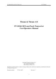
<strong>MX420</strong>/BR<br />
This is a dual-head CDU system where a <strong>MX420</strong>/8 (operating <strong>as</strong> a<br />
m<strong>as</strong>ter) and a <strong>MX420</strong>/2 (operating <strong>as</strong> a slave) are supplied. A smart<br />
DGPS antenna (MX421B-10) is supplied <strong>as</strong> a standard equipment. The<br />
antenna unit is connected only to the <strong>MX420</strong>/8 m<strong>as</strong>ter unit.<br />
MX421B<br />
Smart GPS<br />
Antenna<br />
<strong>MX420</strong> CDU <strong>MX420</strong> CDU<br />
MX 422 Pr ofessional DGPS Navigator<br />
M<strong>as</strong>ter Unit<br />
4 Version 2.0<br />
MX 422 Professional DGPS Navigator<br />
Slave Unit<br />
<strong>MX420</strong> BR Beacon and Remote Configuration<br />
<strong>MX420</strong>/BRIM (Dual Control Integrity Monitor)<br />
This is an enhanced Dual-Control configuration wherein two <strong>MX420</strong>/<br />
8 CDUs and two MX421B-10 smart DGPS antenn<strong>as</strong> are supplied. These<br />
two <strong>MX420</strong>/8 units are connected in dual-control configuration but<br />
they operate <strong>as</strong> independent navigator units with dedicated antenn<strong>as</strong>.<br />
The Integrity Monitor (IM) feature is a software option that works<br />
only in the <strong>MX420</strong>/8 CDU hardware.<br />
This configuration allows data to be shared between two remotely<br />
separated stations (i.e. navigator’s station and helmsman’s station),<br />
with independent access to various information fields. The purpose of<br />
this configuration is to enable each CDU to calculate its own position,<br />
then check the operational status of the other GPS receiver. The GPS<br />
receiver with the best overall operational status then provides the<br />
system position. This provides a fully redundant system, with selfrecovery<br />
capabilities. The Integrity Monitor function can be set to<br />
Automatic switch over, forced to the M<strong>as</strong>ter unit, or forced to the<br />
Slave unit for position and navigation functions.<br />
MX421B<br />
Smart DGPS<br />
Antenna<br />
<strong>MX420</strong>/8 CDU <strong>MX420</strong>/8 CDU<br />
MX 422 Pr ofessi onal D GPS Navigat or<br />
MX421B<br />
Smart DGPS<br />
Antenna<br />
MX 422 Pr ofessional DGPS Navigat or<br />
Unit 1 Unit 2<br />
<strong>MX420</strong>/BRIM <strong>System</strong> Configuration
DGPS Operator’s Manual<br />
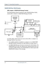
<strong>MX420</strong>/MKD (Minimum Keyboard and Display for AIS)<br />
An entry level <strong>MX420</strong>/AIS CDU model supplied with an IMO-compliant<br />
AIS transponder unit. All the AIS transponder setups and controls<br />
are done through the <strong>MX420</strong>. It also gathers the ship’s sensor data<br />
and organizes the information for transmission via AIS. High-speed<br />
serial data ports are provided for output to the ECDIS chartplotter,<br />
ARPA radar and other shipboard systems.<br />
It also collects and decodes AIS reports from other stations and provides<br />
a readout from all AIS-equipped ships and shore stations. This<br />
model does not have full navigation functions.<br />
<strong>MX420</strong>/AIS<br />
MX 422 Professional D GPS Navigator<br />
MX423 AIS Transponder<br />
GPS<br />
Ant.<br />
<strong>MX420</strong>/AIS B<strong>as</strong>ic Configuration<br />
<strong>MX420</strong>/AIS (AIS & <strong>Navigation</strong> <strong>System</strong>)<br />
An enhanced <strong>MX420</strong>/MKD unit supplied with the Leica MX421B-10<br />
smart DGPS antenna. This model h<strong>as</strong> full navigation and AIS features.<br />
<strong>MX420</strong>/AIS <strong>Navigation</strong> <strong>System</strong> Configuration<br />
The Installation & Service Manual h<strong>as</strong> more details on the parts<br />
supplied with each configuration, and their <strong>as</strong>sociated part numbers.<br />
Note:<br />
1) In general, this manual will refer to all versions of this product line simply<br />
<strong>as</strong> the <strong>MX420</strong> CDU, <strong>MX420</strong>/AIS, CDU or navigator. Where distinction<br />
between models is necessary, the particular model type will be indicated.<br />
Version 2.0 5
Operator’s Manual Keypad & Display Description<br />
2) Three smart GPS/DGPS antenna models are compatible with the <strong>MX420</strong><br />
CDU. They are the MX421-10 (GPS or DGPS), MX525 (DGPS only) and<br />
MX521(GPS or DGPS ).<br />
6 Version 2.0
Keypad & Display Description Operator’s Manual<br />
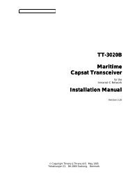
DGPS Beacon <strong>System</strong><br />
Navigator Site<br />
MX 420 <strong>Navigation</strong> <strong>System</strong><br />
RTE<br />
NAV<br />
WP T<br />
PLOTTIDE<br />
A UX<br />
P O S<br />
GP S<br />
DGP S<br />
E<br />
CF G C<br />
Professional / Commercial /<br />
Personal Craft Users<br />
As Maritime Safety Administrations, Navy, and Co<strong>as</strong>t Guard Organizations<br />
realize the limitations of standard GPS positioning, many have<br />
begun installing DGPS Beacon Stations. While an understanding of<br />
this system is not necessary for operating receivers with internal beacon<br />
receivers, you may want to read on to have a better understanding<br />
of how your receiver is capable of achieving the high levels of accuracy<br />
made possible by this network of transmitters.<br />
The DGPS Beacon <strong>System</strong> is comprised of three segments: the reference<br />
station, Integrity Monitor (IM) equipment located at the beacon<br />
site, and the Navigator equipment located on board the user’s boat or<br />
vehicle. The DGPS beacon system design is illustrated below.<br />
Because of the limited range of the beacon transmitters, typically 150<br />
to 400 km, the corrections generated by the reference station are always<br />
valid for users who can receive the correction signals and maintain<br />
a 5 meter or better accuracy figure.<br />
Version 2.0 7
Operator’s Manual Keypad & Display Description<br />
Keypad & Display Description<br />
Traffic<br />
Lights<br />
6289-01A.400<br />
Display<br />
8 Version 2.0<br />
NAV<br />
PLOT<br />
POS<br />
Softkeys Cursor Key<br />
E<br />
Function Keys<br />
RTE<br />
TIDE<br />
Refer to the illustration above. The Traffic Lights on the left side of<br />
the display will tell you how your navigator is operating.<br />
Note: You need to take care in reading the traffic light indications,<br />
<strong>as</strong> there are overlapping possibilities between the<br />
GPS and DGPS modes. If you are unsure of the current<br />
operating mode, select the CFG function key and scroll<br />
down to the DGPS selection. If the DGPS mode is selected<br />
to anything other than Off, then follow the Differential<br />
GPS Traffic Light Operation. If the DGPS mode is<br />
selected to Off, then follow the GPS Traffic Light Operation.<br />
GPS<br />
CFG<br />
WPT<br />
A U X<br />
AIS<br />
C
Keypad & Display Description Operator’s Manual<br />
Differential GPS Traffic Light Operation:<br />
Red Fl<strong>as</strong>hing<br />
Not tracking satellites (no position update). This is normal for the<br />
first 2 minutes or so when turning the unit on. The very first time you<br />
turn the unit on, or if the memory is reset or lost, this condition is also<br />
normal. Allow the receiver to run for at le<strong>as</strong>t 30 minutes under these<br />
circumstances. If it still does not change to Red Solid, refer to the<br />
troubleshooting section of the Installation & Service Manual. An<br />
icon similar to the one at left will be displayed in the upper left corner<br />
of screen.<br />
Red/Yellow Solid<br />
Dead Reckoning . When normal GPS or DGPS operation is not available,<br />
this LED sequence is provided to quickly identify the DR navigation<br />
mode. A DR indicator is also displayed on all screens.<br />
Red Solid<br />
Tracking one or more satellites (no position update). This is also<br />
normal for the first 2 minutes or so when turning the unit on. The very<br />
first time you turn the unit on, allow the receiver to run for at le<strong>as</strong>t 20<br />
minutes after changing to Red Solid to collect an almanac from the<br />
satellites, regardless of whether a position update h<strong>as</strong> been calculated<br />
or not. This is also a normal indication if the HDOP is greater than 10,<br />
if the receiver is tracking too few satellites, or for other re<strong>as</strong>ons <strong>as</strong> well.<br />
Read the GPS and DGPS function screens for more information.<br />
Yellow/Green Solid<br />
GPS position update; DGPS corrections are not being received. You<br />
may see this from time to time during normal operation. It usually<br />
!<br />
occurs when the beacon signal is not available (either it is being blocked<br />
by terrain or a local object or you are out of range of the transmitter)<br />
and/or you are tracking 3, 4, or 5 satellites, and the satellites have poor<br />
geometry relative to your position. The condition will normally go<br />
back to green solid, when it picks up another beacon station. The<br />
factory default level for dropping DGPS corrections is 60 seconds.<br />
During this period, your positioning information is less than optimal,<br />
and position accuracy may be off by <strong>as</strong> much <strong>as</strong> 3 to 5 meters. Press<br />
the GPS function key and refer to the DGPS section in this manual for<br />
guidance if this light condition occurs.<br />
Version 2.0 9
Operator’s Manual Keypad & Display Description<br />
Yellow Solid<br />
DGPS position update with poor HDOP value. You may see this from<br />
time to time during normal operation. It usually occurs when you are<br />
tracking 3, 4, or 5 satellites, and the satellites have poor geometry<br />
relative to your position. The condition will normally go back to Green<br />
Solid when it picks up another satellite or the geometry of the existing<br />
satellites improves. The factory default level for this indication is with<br />
an HDOP of 4 to 10. During this period, your positioning information is<br />
less than optimal, and position accuracy may be off by <strong>as</strong> much <strong>as</strong> 5 to<br />
10 meters. You can press the GPS function key and refer to the GPS<br />
section in this manual for guidance if this light condition occurs.<br />
Green Solid<br />
DGPS position update with HDOP value less than 4. This is the<br />
normal operating condition. Position accuracy is normally better than<br />
3 meters. Keep in mind that position accuracy is always only <strong>as</strong> good<br />
<strong>as</strong> the corrections received, their age, your distance from the reference<br />
station, and the geometry of the satellites. This is the normal operating<br />
condition and no icon will be displayed.<br />
GPS Traffic Light Operation:<br />
Red Fl<strong>as</strong>hing<br />
Not tracking satellites (no position update). This is normal for the<br />
first 2 minutes or so when turning the unit on. The very first time you<br />
turn the unit on, or if the memory is reset or lost, this condition is also<br />
normal. Allow the receiver to run for at le<strong>as</strong>t 30 minutes under these<br />
circumstances. If it still does not change to Red Solid, refer to the<br />
troubleshooting section of the Installation & Service Manual. An<br />
icon similar to the one at left will be displayed in the upper left corner<br />
of the screen.<br />
Red/Yellow Solid<br />
Dead Reckoning . When normal GPS or DGPS operation is not available,<br />
this LED sequence is provided to quickly identify the DR navigation<br />
mode. A DR indicator is also displayed on all screens in the upper<br />
left hand corner of the display.<br />
Red Solid<br />
Tracking one or more satellites (no position update). This is also<br />
normal for the first 2 minutes or so when turning the unit on. The very<br />
first time you turn the unit on, allow the receiver to run for at le<strong>as</strong>t 20<br />
10 Version 2.0
Keypad & Display Description Operator’s Manual<br />
minutes after changing to Red Solid to collect an almanac from the<br />
satellites, regardless of whether a position update h<strong>as</strong> been calculated<br />
or not. This is also a normal indication if the HDOP is greater than 10.<br />
The HDOP value can be read in the GPS function screens.<br />
Yellow Solid<br />
GPS position update h<strong>as</strong> a poor HDOP value. You may see this from<br />
time to time during normal operation. It usually occurs when you are<br />
tracking 3, 4, or 5 satellites, and the satellites have poor geometry<br />
relative to your position. If you are patient, the condition will normally<br />
go back to Green Solid when you pick up another satellite or the geometry<br />
of the existing satellites improves. The factory default level for<br />
this indication is with an HDOP of 4 to 10. During this period, your<br />
positioning information is less than optimal, and position accuracy<br />
may be off by <strong>as</strong> much <strong>as</strong> 10 to 30 meters. You can press the GPS<br />
function key and refer to the GPS section in this manual for guidance<br />
if this light condition occurs.<br />
Green Solid<br />
GPS position update with HDOP value less than 4. This is the normal<br />
operating condition. Position accuracy is normally between 3 to 5<br />
meters, but can be out <strong>as</strong> much <strong>as</strong> 30 meters. Keep in mind that position<br />
accuracy is always only <strong>as</strong> good <strong>as</strong> the geometry of the satellites<br />
and the navigation information provided by the satellites. This is the<br />
normal operating condition and no icon will be displayed.<br />
The Display:<br />
The CDU uses a Transflective LCD display screen. It provides optimum<br />
viewing in virtually all lighting conditions. To change the display<br />
contr<strong>as</strong>t or backlight condition, select the CFG function key and scroll<br />
down to the Lighting menu choice. Refer to the CFG section of the<br />
manual for a complete description of menu options. The function key<br />
( ) just above the Power On/Off key allows you to quickly change<br />
between daytime and night time screen settings.<br />
Information displayed on the screen is normally divided into windows,<br />
similar to what you might see on a normal computer. Each screen h<strong>as</strong> a<br />
page number in the upper left hand corner . These page numbers<br />
are there to help you quickly find the information you need, and<br />
to help us guide you on the rare occ<strong>as</strong>ion that you might request our<br />
<strong>as</strong>sistance.<br />
Version 2.0 11
Operator’s Manual Keypad & Display Description<br />
With the exception of a portion of the PLOT and MOB screens which<br />
use two softkeys to change the view scale, all of the screens require<br />
that you press the E (Edit Mode) function key before you are allowed<br />
to change data on the screen. You can use the cursor key (the big key<br />
with the arrows pointing in four directions) to move between edit fields<br />
or menu choices on most screens when in the edit mode. When you<br />
are not in the edit mode, you can use the cursor to scroll between<br />
screens (i.e. NAV1, NAV2, NAV3, ...) or to move up and down on screens<br />
(like the menu bar in the CFG screen).<br />
The Softkeys:<br />
The five softkeys under the display are so named because their purpose<br />
changes from one menu or screen to the next. With the exception<br />
of a portion of the PLOT screens and the MOB screens, all of the<br />
screens require that you press the E (Edit Mode) function key before<br />
the softkeys can be accessed. Don’t forget to press the E function key<br />
when you have finished editing a screen.<br />
The Function Keys:<br />
The Function Keys are the keys to the right of the display. There are 18<br />
function keys in all. Eleven of the function keys access various screen<br />
and editing displays. Three of these keys are used for editing or moving<br />
within the screens. One key is used to mark your present position,<br />
another is used strictly for Man Over Board alarms. One switches<br />
between two display lighting options, and finally there is the power<br />
on/off key.<br />
The ten function keys with alpha abbreviations on them are described<br />
in the ensuing chapters. The eight function keys with symbols are<br />
described below.<br />
The function keys are also used in the edit mode to enter alphanumeric<br />
information into screen data fields.<br />
Mark Position<br />
This function key stores your present position, date and time at the<br />
next available waypoint location in the Waypoint Bank. A window<br />
pops up on the screen to confirm your key depression, and to tell you<br />
where the mark position is being stored. You can go into the WPT<br />
menu and edit the coordinates or description later. The CDU is also<br />
12 Version 2.0
Keypad & Display Description Operator’s Manual<br />
capable of performing this function from a remote contact closure input<br />
via Cable B (MOB/Event) wire. Refer to the Installation & Service<br />
Manual for interface instructions.<br />
GOTO<br />
LIGHT<br />
This function key allows you to quickly create a route from your present<br />
position to one other waypoint. This single waypoint route can use an<br />
existing waypoint from the Waypoint Bank, or you can quickly create<br />
one by either defining the appropriate coordinates or specifying a<br />
range and bearing.<br />
Be careful when you use this selection, <strong>as</strong> it will er<strong>as</strong>e your current<br />
active route when it creates the new one. Read through the ROUTE<br />
and PLOT sections of this manual to find other ways to use this key<br />
within an active route.<br />
This function key allows you to quickly switch between two predetermined<br />
display lighting conditions. You can have two daytime settings,<br />
two night time settings, or a daytime/night time setting. Select the CFG<br />
function key and scroll down to the Lighting menu choice to make the<br />
desired adjustments. Refer to the Configuration section of the manual<br />
for a complete description of the Lighting menu options.<br />
POWER ON/OFF<br />
This function key turns the unit on and off. When depressed while the<br />
unit is on, you will be prompted to select a YES or NO softkey to<br />
confirm your action. This is known <strong>as</strong> a software power off.<br />
If the operating program should hang up for any re<strong>as</strong>on, you can also<br />
perform a hardware power off by continuing to depress the power on/<br />
off function key for about 5 seconds. When the GPS is turned off<br />
using this technique, you can not reapply power for 10 seconds.<br />
Note: An occ<strong>as</strong>ion may arise when you need to reset the memory back to the<br />
factory default values. Doing this will cause the CDU to lose all of your<br />
defined settings, <strong>as</strong> well <strong>as</strong> all 2,000 of your waypoints and routes. If<br />
you hold down the fifth (right most) softkey when power is applied for<br />
about two seconds, until you hear a key click, then the memory will<br />
be reset.<br />
Version 2.0 13
Operator’s Manual Keypad & Display Description<br />
MAN OVER BOARD (MOB)<br />
This dedicated function key is located at the bottom right hand corner<br />
of the front panel. When depressed for a few seconds, it activates a<br />
number of automatic functions:<br />
� Most obviously, it brings up an MOB1 (Plot) screen.This is an<br />
automatic scaling screen which selects the best zoom level to<br />
display your present position and the MOB position. In addition,<br />
the MOB position is displayed in the upper left corner, so that you<br />
can quickly read the coordinates to others who may be available<br />
to render <strong>as</strong>sistance. This plot screen also provides the vital bearing<br />
and distance back to the MOB position, <strong>as</strong> well <strong>as</strong> your present<br />
course over ground.<br />
� The MOB position, date and time are stored in the Waypoint Bank<br />
for future reference (e.g. log book entries).<br />
� <strong>Navigation</strong> data output on the NMEA ports (i.e. BWC and BWR),<br />
are changed to reflect the current crisis situation. This way, other<br />
interfaced equipment can also help guide you back to the MOB<br />
position. When the MOB condition is canceled via a MOB screen<br />
softkey, the NMEA sentences will automatically revert to the active<br />
route information. Don’t forget to cancel the MOB so your<br />
interfaced equipment will read the correct data!<br />
� The MOB function key and remote MOB input are disabled from<br />
subsequent activation, until the MOB Cancel softkey is selected.<br />
� Other functions such <strong>as</strong> Position and Navigate can still be accessed;<br />
however, the screen will revert to the MOB Plot screen<br />
after 30 seconds. Bearing and distance information in these other<br />
screens relate to the MOB position, not the next waypoint in the<br />
active route, until MOB is canceled.<br />
To cancel a MOB condition, make sure you are in the MOB Plot screen.<br />
Press the E function key, then select the Cancel MOB softkey.<br />
This <strong>MX420</strong> receiver is also capable of performing the MOB function<br />
from a remote contact closure. If the contact closure is made for less<br />
14 Version 2.0
Navigate Operator’s Manual<br />
than 2 seconds, the input is registered <strong>as</strong> a Mark Position. If the contact<br />
closure is made for more than 2 seconds, the input is registered <strong>as</strong><br />
a MOB Position. Refer to the Installation & Service Manual for interface<br />
instructions.<br />
E (EDIT)<br />
C C (CLEAR)<br />
CURSOR<br />
1<br />
NAV<br />
ABC FUNCTION<br />
This function key activates or deactivates the softkeys and edit fields<br />
within any screen where editing is appropriate. You will quickly learn<br />
that this is an important operating feature in the unit. Press the E key<br />
when you want to start editing a screen and again when you have<br />
finished editing. If after editing you press a function key and nothing<br />
seems to happen, check to make sure you didn’t accidentally alter<br />
your information and press the E key to end editing. Most edit screens<br />
provides an Escape softkey. If you decide for some re<strong>as</strong>on that you<br />
don’t want to use the changes you have made, pressing the Escape<br />
softkey will restore the original information. However, once you press<br />
the E key, all changes are accepted and the original data is lost.<br />
This function key is probably the le<strong>as</strong>t used of all the function keys;<br />
however, it can save you some otherwise frustrating editing time. This<br />
key allows you to er<strong>as</strong>e or clear one character at a time. If you hold it<br />
down, it will er<strong>as</strong>e the entire line that the cursor is currently on.<br />
This function key is the most used of all the function keys. As its name<br />
suggests, this key is used to move between edit fields. It also allows<br />
you to move between function screen pages (by pressing left or right).<br />
In addition, many of the edit fields allow you to use either the cursor<br />
key or the Change softkey to scroll through or select from predetermined<br />
choices.<br />
You might have noticed that above and below each primary function<br />
key there are numbers and letters. These numbers and letters are used<br />
Version 2.0 15
Operator’s Manual Navigate<br />
when you are in the edit mode. You will find that they are most often<br />
used in the RTE, WPT, and CFG screens, but they are used in other<br />
screens <strong>as</strong> well. If you are trying to enter text, simply locate the desired<br />
letter and press the appropriate key repeatedly until the appropriate<br />
letter or number appears. If you accidentally go p<strong>as</strong>t the desired letter,<br />
repeat pressing the key and the letter will come up again. You can<br />
toggle between upper and lower c<strong>as</strong>e characters by pressing the key<br />
for a long period.<br />
You will also find that some screens allow you to input symbols into<br />
the text fields. These symbols are selected through a softkey selection<br />
where symbols are allowed. Don’t forget to press the ‘E’ key to get out<br />
of the edit mode!<br />
Another helpful feature on this CDU is that successive depressions<br />
on the function key (when not in the edit mode) allow you to page<br />
through all of the screens available for that particular function. You<br />
can accomplish the same thing by selecting a function and using the<br />
left and right arrows on the cursor key (which is sometimes f<strong>as</strong>ter).<br />
Whichever method you choose, it is impossible to get lost between<br />
function screens. In addition, the software remembers which screen<br />
you used l<strong>as</strong>t for each function. Each time you reenter a function (e.g.<br />
you go from PLOT to NAV), you will enter the l<strong>as</strong>t screen you viewed<br />
for that function. You can change this setting in the CFG 1 Operation.<br />
Use the <strong>as</strong>sociated function key to access the international character<br />
desired (i.e. A for Æ). The international characters supported are:<br />
ABC = Ä, Å, Æ, À, Ç<br />
DEF = É, È<br />
GHI = Í<br />
MNO = Ñ, Ó, Ö<br />
STU = Ú, Ü<br />
Use the CFG key when in the edit mode to cycle through these other<br />
optional characters.<br />
‘ “ $ & ! ( ) ? / + - ° . , :<br />
16 Version 2.0
Navigate Operator’s Manual<br />
AIS<br />
9<br />
YZ<br />
Automatic Identification <strong>System</strong> (AIS)<br />
This is a special function key used to display the various AIS related<br />
data. You can page through the various AIS screens by pressing the<br />
AIS key repeatedly. More information about the AIS displays are available<br />
in ‘Appendix-A Automatic Identification <strong>System</strong>’ on pages 131<br />
through 150 of this manual. The number and letters on the top and<br />
bottom of the AIS key can be used in the editing mode.<br />
Note: The AIS display key is not functional in the <strong>MX420</strong>/2 and <strong>MX420</strong>/8 models.<br />
This is a special key that is active only in the <strong>MX420</strong>/AIS or MKD<br />
models. Non-AIS models will show the message “AIS Not Available on<br />
this Version” when the AIS key is pressed.<br />
Version 2.0 17
Operator’s Manual Navigate<br />
Navigate<br />
There are four b<strong>as</strong>ic NAV screens. NAV4 only provides data if appropriate<br />
sensors (e.g. wind speed/direction logs, NMEA comp<strong>as</strong>s, etc.)<br />
are interfaced and activated on the CDU. The NAV functions are highly<br />
interactive with the RTE1 screen, and a number of CFG menu selections.<br />
The RTE1 screen provides the active route for the NAV screens. It<br />
also maintains a waypoint p<strong>as</strong>s log for you. One other important feature<br />
in the RTE1 screen that you need to be aware of is that the up and<br />
down arrow softkeys control which waypoints are skipped (down arrow)<br />
and which are restored (up arrow) for your current route. The ETA<br />
information is configured in the RTE 1 screen. Refer to the Route section<br />
of the manual for a full description.<br />
The following CFG menus directly impact the NAV functions:<br />
� COG SOG - sets the filtering time for the displayed values.<br />
� Datum - sets the reference datum for your present position and<br />
waypoints in the active route.<br />
� GPS Offset - sets an offset for calculating the GPS antenna position<br />
if you can’t physically locate the antenna exactly where you<br />
want it (e.g. over the centerline of the boat).<br />
� <strong>Navigation</strong> - sets a variety of important functions and alarms<br />
� Rhumb line or Great Circle navigation<br />
� Range units: nautical miles, nautical miles and meters<br />
(when under 1000 meters), nautical miles and feet (when<br />
under 1000 feet), statute miles, statute miles and meters<br />
(when under 1000 meters), statute miles and feet (when<br />
under 1000 feet), kilometers, or kilometers and meters<br />
(when under 1000 meters)<br />
� Cross-track error limit and alarm control<br />
� Waypoint p<strong>as</strong>s criterion and distance: bisector line, perpendicular<br />
line, complex (combination of bisector line<br />
and perpendicular line), distance to waypoint, or manual<br />
� Waypoint Approach distance<br />
18 Version 2.0
Navigate Operator’s Manual<br />
� Autopilot alarm control<br />
� Position - sets 2D or 3D mode, antenna height, Lat/Lon, Loran or<br />
UTM, and some alarm limits. There is an optional software package<br />
available to setup a user grid <strong>as</strong> well. The option is explained<br />
in the Position, and CFG Position sections of this manual.<br />
� Time - sets appropriate offsets, and 12 or 24 hour clock mode.<br />
� Various NMEA input controls for sensors (i.e. speed log, wind<br />
instruments, etc).<br />
You have probably already figured out that you will need to pay close<br />
attention to the configuration screens. The good news is that you<br />
should only have to setup one time. Keep in mind, though, that you<br />
may need to revisit these and other configuration screens from time to<br />
time to get the CDU to do exactly what you want it to.<br />
Dead Reckoning<br />
The <strong>MX420</strong> CDU is capable of Dead Reckoning (DR) calculation when<br />
appropriate comp<strong>as</strong>s/heading and speed log sensors are connected<br />
and activated. Refer to the NAV4 and CFG sections of this document.<br />
When the CDU is in the DR mode a DR icon is displayed in the upper<br />
left portion of the screen.<br />
NAV1 - The Panorama Screen<br />
This screen is designed to give you a unique 3 dimensional look at the<br />
active route you are to follow. It is typically referred to <strong>as</strong> a runway<br />
view because you can see navigation markers, your course line, the<br />
cross-track error lines, and waypoint flags <strong>as</strong> you p<strong>as</strong>s them. Take a<br />
look at the example below.<br />
If you don’t see the information described in this screen, you will need<br />
to create a route in RTE1 first.<br />
Version 2.0 19
Operator’s Manual Navigate<br />
The somewhat triangular shape at the bottom center of the screen<br />
represents the bow of the boat. Icons on the screen are always related<br />
to this object. The two d<strong>as</strong>h lines extending from the bottom of the<br />
screen towards the center of the screen represent your cross-track<br />
error limits. The dotted line extending from the bow of the boat icon<br />
represents your course line. The course line changes direction at the<br />
flags, which represent your waypoints, and continues through to the<br />
end of the active route you entered in RTE1. Notice that the crosstrack<br />
error lines end at the first flag. As you p<strong>as</strong>s the flag and start the<br />
next leg of your course, these lines will be redrawn to reflect the course<br />
change. Icons that you see left and right of your course are navigation<br />
markers that you define in the Waypoint Bank (WPT1) where a symbol<br />
is used <strong>as</strong> the first character of the waypoint description. The<br />
Panorama and Plot screens will automatically place these navigation<br />
markers on the screen <strong>as</strong> you approach them.<br />
The degree values that you see are your Course Over Ground (COG),<br />
<strong>as</strong> calculated by the GPS receiver’s position fix to position fix, and<br />
Bearing (BRG) from your present position to the waypoint. The speed<br />
value is your Speed Over Ground (SOG) <strong>as</strong> calculated by the GPS. The<br />
distance value displayed <strong>as</strong> the Range (RNG) is calculated from your<br />
present position to the waypoint. The Time-To-Go (TTG) is the calculated<br />
time it will take you to reach the waypoint, b<strong>as</strong>ed on your Waypoint<br />
Closure Velocity (see NAV4 description).<br />
To keep the screen from jumping around when you are stopped, the<br />
screen freezes the graphic representation when your speed is under<br />
0.5 Kn in DGPS mode or 2.0 Kn in GPS mode. Once you get underway,<br />
your course details will update appropriately.<br />
You will see a RL or GC symbol in the upper right corner of the display<br />
indicating whether you are navigating under Rhumb Line or Great<br />
Circle. This is set in the CFG Navigate menu.<br />
20 Version 2.0
Navigate Operator’s Manual<br />
If you press the E key, the Panorama Display Option screen will allow<br />
you to customize the information presented.<br />
� View - allows you to adjust the display for a Close (zoomed-in) or<br />
a Far (zoomed-out) representation of your route.<br />
� Show Waypoints - allows you to turn waypoints which are not<br />
part of the active route on and off.<br />
� Show Active Route - allows you to turn the course line on or off<br />
on the display (<strong>as</strong>suming a symbol is entered for the first character<br />
of the waypoint name).<br />
� Show Off Track Limit - allows you to turn the cross-track error<br />
limit lines on or off on the display.<br />
� Show Data Window - allows you to select between the two NAV 1<br />
display types depicted at the beginning of this section, one in<br />
which the data is displayed in various parts of the graphic screen,<br />
the other in which the data is displayed in a separate window to<br />
the left of the graphic screen.<br />
If you drift outside of your cross-track error limit and you decide not to<br />
return to your original course line, you can reset your course line from<br />
your present position to the waypoint by selecting Reset XTE from the<br />
display.<br />
The Skip Waypoint softkey allows you to skip the waypoint you are<br />
presently going to, and advance to the next waypoint. For example, if<br />
you were under way and nearing waypoint 5 and you decide you want<br />
to go on to waypoint 6 now, press Skip Waypoint. If you make a<br />
mistake and you want to go back (unskip) to waypoint 5, you can do<br />
this by the following:<br />
1. Go into the RTE1 screen.<br />
2. Press E in the RTE1 screen.<br />
3. Select the Route Control softkey.<br />
4. Press the up arrow softkey (fourth from the left) once.<br />
5. Press the E key again.<br />
Refer to the Route section of this manual for more details about skipping<br />
and unskipping waypoints.<br />
Version 2.0 21
Operator’s Manual Navigate<br />
NAV2 - B<strong>as</strong>ic Steering Information<br />
Navigate screen 2 provides the bearing (BRG) and range (RNG) to the<br />
waypoint you are approaching in large e<strong>as</strong>ily viewed characters. Below<br />
these, you will see your actual Course Over Ground (COG) and<br />
Speed Over Ground (SOG). The bottom portion of the screen provides<br />
cross-track error information. Again, if you don’t see the information<br />
described here on your screen, you will need to create a route in RTE1<br />
first (refer to the Route section of the manual).<br />
In the bottom half of the window, the vertical line in the center represents<br />
your course line. The checkered area on the left and right side of<br />
this area represents the out of bounds or beyond the cross-track error<br />
limit area. Whenever the boat is left or right of the course line, the<br />
corresponding checkered area changes to solid black, indicating the<br />
side of the course line that you are on. The number next to the course<br />
line is your calculated cross-track error. The numbers in the lower left<br />
and right hand corners indicate the cross-track limit you set in the<br />
CFG1 menu under <strong>Navigation</strong>. You will notice that the cross-track<br />
error limit lines are slanted, just <strong>as</strong> they were in the Panorama screen.<br />
So if the boat is off to the right of the course, and the bow is pointing<br />
straight up, you are actually traveling away from the course line. Keep<br />
the bow pointed toward the top of the course line, and you should be<br />
able to maintain your course without a lot of drift. The BRG and COG<br />
values will confirm this for you, when executed properly.<br />
22 Version 2.0
Navigate Operator’s Manual<br />
From time to time, you might drift off course and decide not to return to<br />
your original course line. If you drift outside of your cross-track error<br />
limit, you can reset your course line from your present position to the<br />
waypoint by pressing the E key and selecting Reset XTE from the<br />
display. This will save your autopilot from having to work hard to get<br />
you back on course. Press the E key again to get back into normal<br />
display mode.<br />
In addition, if you decide you want to skip this waypoint, and go on to<br />
the next one, Press the E key, and the Skip Waypoint softkey one time.<br />
Press the E key to end this procedure. If you skip one waypoint manually,<br />
and the CDU starts skipping more waypoints by itself, you probably<br />
need to change your Waypoint P<strong>as</strong>s Criteria in the CFG1 Navigate<br />
menu. Refer to the Route section of this manual for more details<br />
about skipping waypoints.<br />
Just <strong>as</strong> in NAV1, you will see an RL or GC symbol in the upper right<br />
corner of the display indicating whether you are navigating under<br />
Rhumb Line or Great Circle. This is set in the CFG1 Navigate menu.<br />
NAV 3 - Expanded <strong>Navigation</strong> Information<br />
Navigate screen 3 h<strong>as</strong> four windows. The upper left window is a<br />
smaller version of NAV2. Ple<strong>as</strong>e read the previous section for a detailed<br />
description of this window. The two windows below this one<br />
indicate the current date, time and the ETA to the end of your route for<br />
the time zone currently entered. The date and time format is set in the<br />
CFG1 Time menu. The ETA and TTG (in the right hand window) are<br />
filtered over time, so allow the filtering to settle when you first make a<br />
course or speed change. The filter time is controlled in the RTE1 ETA<br />
Setup screen. The Time-To-Go (TTG) value on the bottom of the right<br />
hand window expands from HH:MM:SS to HHHH:MM:SS when the<br />
time to go is greater than 99:59:59. Also, these values are calculated by<br />
using your Waypoint Closure Velocity (WCV), not your SOG. WCV is<br />
described in short detail in the NAV4 section which follows.<br />
Version 2.0 23
Operator’s Manual Navigate<br />
You will find the right hand window to be a helpful tool. In addition to<br />
identifying the waypoint you are currently approaching, it identifies<br />
the waypoint at the end of the next leg. The really unique feature of<br />
this screen is the graphical representation of your actual course line<br />
approach angle relative to the next leg of your course. This approach<br />
angle is continuously updated in real time and will help you setup for<br />
course changes.<br />
Reset XTE and Skip Waypoint, described at the end of NAV2, is also<br />
available in NAV3.<br />
NAV4 - Sensor Input <strong>Navigation</strong><br />
The NAV 4 screen applies the wind instruments, speed log, comp<strong>as</strong>s,<br />
and depth sounder inputs from external sensors to your active route,<br />
<strong>as</strong> appropriate. You can setup the sensors in the CFG1 screen. The<br />
Installation & Service Manual will guide you through the interfacing<br />
capabilities of the CDU.<br />
Use the following CFG1 menus to set this screen up:<br />
Comp<strong>as</strong>s - Sets the input port number, comp<strong>as</strong>s type (true or magnetic),<br />
comp<strong>as</strong>s deviation table, and the input NMEA 0183 record<br />
from which to derive the comp<strong>as</strong>s information. The NMEA 0183<br />
record should be specified by the user, because several NMEA<br />
0183 records may contain comp<strong>as</strong>s information. This provides you<br />
the capability of knowing the comp<strong>as</strong>s source exactly. The CDU<br />
only accepts NMEA 0183 formatted data for the comp<strong>as</strong>s input.<br />
Synchro or stepper gyro comp<strong>as</strong>ses are not compatible.<br />
Depth - Sets the input port number, units of me<strong>as</strong>ure for depths and<br />
tide data, sensor offset, alarms, and the input NMEA 0183 record<br />
from which to derive the depth information. The NMEA 0183 record<br />
should be specified by the user, because several NMEA 0183<br />
24 Version 2.0
Navigate Operator’s Manual<br />
records may contain depth information. This provides you the capability<br />
of knowing the depth source exactly.<br />
Log - Sets the input port number, sensor type (pulse or NMEA 0183),<br />
sensor offset, alarms, and a correction factor (if needed).<br />
Set & Drift - Sets the mode to manual or automatic (derived from GPS).<br />
Sets the time-out before applying calculated values. GPS calculated<br />
values are used prior to the time-out period.<br />
Wind - Sets the input port number, units of me<strong>as</strong>ure, sensor offset,<br />
alarms, and the input NMEA 0183 record from which to derive the<br />
wind information. The NMEA 0183 record should be specified by<br />
the user, because several NMEA 0183 records may contain wind<br />
information. This provides you the capability of knowing the wind<br />
source exactly.<br />
This screen is divided into four windows. The window on the top left<br />
provides details relating to the True Wind Angle (TWA), True Wind<br />
Speed (TWS) and True Wind Direction (TWD), which are taken from<br />
the NMEA 0183 record of MWV or VWR. If the wind information is<br />
given in relative terms, the CDU calculates true values using available<br />
GPS course and speed information to make the necessary adjustments.<br />
Refer to the Glossary for definitions on Apparent/True Wind Angle/<br />
Speed/Direction. To the right of the wind information is your Velocity<br />
Made Good (VMG) towards the waypoint. The VMG data is filtered to<br />
show the average speed from the l<strong>as</strong>t waypoint to your present position<br />
towards the next waypoint. VMG is calculated from GPS data.<br />
The CDU will also use the above data to calculate your speed parallel<br />
to wind and can output the VPW NMEA 0183 data sentence to other<br />
on-board instruments.<br />
Version 2.0 25
Operator’s Manual Navigate<br />
The window below the wind data provides information relating to your<br />
course and speed. You will find the Course Over Ground (COG calculated<br />
by the MX421 smart GPS antenna), Heading (HDG, your NMEA<br />
0183 comp<strong>as</strong>s input), and Heading To Steer (HTS) data on the left side<br />
of the window. HTS data is calculated by considering your Heading,<br />
minus COG and adding BRG to the waypoint. In doing so, the software<br />
considers any Set to be included in the HDG value. If there is no<br />
Set, your HDG should be equal to COG. Set and Drift is calculated from<br />
GPS and your Speed Log (NMEA 0183 VHW record or Pulse input)<br />
and Comp<strong>as</strong>s (NMEA 0183 HDM, HDT, or VHW) input or an operator<br />
manual input.<br />
On the right side of the lower left window you will find the Speed Over<br />
Ground (SOG, calculated by MX421 smart GPS antenna), Speed Log<br />
(LOG, the NMEA 0183 or pulse speed input), and the Waypoint Closure<br />
Velocity (WCV). WCV reflects the real time velocity from your<br />
present position and course towards the next waypoint. The VMG<br />
and WCV are calculated from GPS data. Refer to the diagram below to<br />
see a graphical representation between VMG and WCV.<br />
26 Version 2.0
Route Operator’s Manual<br />
Velocity Made Good:<br />
Beginning<br />
Waypoint<br />
Actual Course Line<br />
VMG Towards Waypoint<br />
10 Kn<br />
Beginning<br />
Waypoint<br />
Original Course Line<br />
6297_01B.100<br />
Distance to<br />
Waypoint Travelled<br />
Waypoint Closure Velocity:<br />
Effect of Set & Drift<br />
Present<br />
Position<br />
SOG 13 Kn<br />
Effect of<br />
Set & Drift<br />
Original Course Line<br />
Present<br />
Position<br />
SOG 13 Kn<br />
WCV 9 Kn<br />
WCV is b<strong>as</strong>ed on<br />
Extended Course<br />
Line (COG), SOG,<br />
BRG & RNG to WPT<br />
Next<br />
Waypoint<br />
Version 2.0 27<br />
BRG<br />
Extended Course Line<br />
BRG & RNG<br />
Next<br />
Waypoint<br />
HTS to<br />
counter<br />
Set & Drift<br />
Below this information, you will find your Set and Drift data, which is<br />
calculated using GPS and your comp<strong>as</strong>s and speed sensor inputs.<br />
Reset XTE and Skip Waypoint, described at the end of NAV2, is also<br />
available in NAV4.<br />
The window on the right displays depth information coming from the<br />
depth sounder unit using the NMEA 0183 record of DPT, DBS, DBT, or<br />
DBK. These are setup in the CFG1 Depth screen, refer to the Configuration<br />
section of the manual and the Installation & Service Manual<br />
for full details on depth data.<br />
Below the depth data you will find the next route leg vector, the Range<br />
to the waypoint and Time To Go data, explained in the NAV3 section.<br />
Note: The NAV function is not active in the <strong>MX420</strong>/AIS B<strong>as</strong>ic model<br />
without the MX421 antenna.
Operator’s Manual Route<br />
Route<br />
There are two RTE screens. The NAV functions are highly interactive<br />
with the RTE1 screen. The RTE2 screen allows you to create a pool of<br />
predetermined routes that you might use often, so you need only<br />
create the route one time. Routes are created from waypoints. All<br />
waypoints are stored in the Waypoint Bank, regardless of which function<br />
is used to create them. Waypoints are either created in the<br />
Waypoint Bank (WPT1), created by the GOTO function, selected<br />
from the PLOT screens in conjunction with the GOTO function, or<br />
from New Waypoints that can be defined in the Route Insert menu<br />
(and simultaneously stored in the route and the Waypoint Bank).<br />
We recognize the diverse needs of professional users. We have designed<br />
the route features to be very flexible to meet a wide range of<br />
users’ requirements by allowing up to 2000 waypoints to be stored<br />
between all of the routes. You can create up to 100 routes, with any<br />
number of waypoints, providing the maximum number of 2000<br />
waypoints between all routes is not exceeded.<br />
The Route (RTE) function serves two purposes:<br />
1. The RTE1 screen provides all of the current, or active waypoint<br />
navigation data to the Navigate and Plot screens and is referred to<br />
<strong>as</strong> the Active Route. Therefore, whenever you begin a new trip or<br />
voyage, you should er<strong>as</strong>e the previous voyage’s waypoints in this<br />
screen, then insert the new waypoints or routes (from RTE2) for<br />
the new voyage. If you want to store the waypoints from the<br />
previous active route for future use, you can copy these waypoints<br />
in the order in which they were entered to the Route Bank in the<br />
RTE2 screen. This is described in the RTE2 - The Route Bank<br />
section of this manual. If you do not clear the RTE1 screen (refer to<br />
Er<strong>as</strong>ing an Existing Route section of this manual), the RTE1 screen<br />
will grow each time you add new waypoints to the route. The route<br />
function can hold a maximum of 2,000 waypoints between the routes<br />
stored in RTE1 and RTE2.<br />
2. The RTE2 screen provides storage space for up to 100 user defined<br />
routes. You can pre-define routes, or copy new routes from the<br />
RTE1 (active route) screen. Later you can choose individual routes<br />
or link two or more routes in the RTE1 screen (refer to Creating a<br />
Multi-Waypoint Active Route section of this manual). When you<br />
are finished using the copied route in RTE1, you can er<strong>as</strong>e the<br />
route from the RTE1 screen and the original stored route will re-<br />
28 Version 2.0
GOTO Operator’s Manual<br />
main intact in the RTE2 screen.<br />
The following CFG1 menus directly impact the RTE functions:<br />
� <strong>Navigation</strong> - sets a variety of important functions and alarms.<br />
� Rhumb line or Great Circle navigation<br />
� Range units: nautical miles, nautical miles and meters (when<br />
under 1,000 meters), nautical miles and feet (when under 1,000<br />
feet), statute miles, statute miles and meters (when under 1,000<br />
meters), statute miles and feet (when under 1,000 feet), kilometers,<br />
or kilometers and meters (when under 1,000 meters)<br />
� Waypoint p<strong>as</strong>s criterion and distance: bisector line, perpendicular<br />
line, complex (combination of bisector line and perpendicular<br />
line), distance to waypoint, or manual.<br />
� Waypoint Approach distance<br />
� Autopilot alarm control<br />
� Position - sets 2D or 3D mode, antenna height, Lat/Lon, Loran,<br />
UTM, or User Grid (optional), and some alarm limits.<br />
� Time - sets time offsets and 12 or 24 hour clock mode (for ETA<br />
calculation, and waypoint p<strong>as</strong>sed time stamp).<br />
RTE1 - The Active Route<br />
The RTE1 screen provides the active route data for the NAV and<br />
PLOT screens. It also maintains a waypoint p<strong>as</strong>s log for you. Another<br />
important feature in the RTE1 screen that you need to be aware of is<br />
that the up (�) and down (�) arrow softkeys, displayed when you<br />
are in the edit mode under the Route Control softkey, control which<br />
waypoints are skipped (down arrow - �) and which are restored (up<br />
arrow - �) for your current route.<br />
Note: The CDU will recalculate the route when a navigation mode,<br />
either Rhumb Line or Great Circle is selected.<br />
You can enter waypoints using different datums into the<br />
route<br />
The RTE1 screen is where you are likely to do most of your trip preparation.<br />
There are several methods you can use to create routes. You are<br />
sure to find one or more methods which meet your needs in the following<br />
sections.<br />
Version 2.0 29
Operator’s Manual Route<br />
Creating a Route Using the GOTO Key:<br />
Using the GOTO function key is the f<strong>as</strong>test way to create a single leg<br />
route. Using this method will cause the existing active route to be<br />
er<strong>as</strong>ed and overwritten with the new position you define.<br />
1. From any screen, press the GOTO key.<br />
2. Press the E key.<br />
3. Select the waypoint determination method you want:<br />
Waypoint Number - allows you to choose a waypoint stored in the<br />
Waypoint Bank. This feature is nice to use if you already know<br />
the waypoint number that you want to go to and you don’t<br />
want to w<strong>as</strong>te time scrolling through the available waypoints.<br />
Enter the number of the waypoint, verify that the coordinates<br />
are correct, and press the E key to copy the waypoint to the<br />
active route.<br />
Choose In Bank - allows you to scroll through the Waypoint Bank.<br />
Align the cursor with the desired waypoint and press the E<br />
key. The waypoint is automatically inserted into the active<br />
route and the unit will revert to the NAV screens, displaying<br />
bearing and distance to this waypoint.<br />
30 Version 2.0
Route Operator’s Manual<br />
Lat. Lon., Grid Point, Loran C TD’s - allows you to define a coordinate<br />
and description, which is also stored at the next available<br />
waypoint location in the Waypoint Bank. Once the coordinates<br />
are defined, press the E key to copy the waypoint to the<br />
active route.<br />
Bearing Range - allows you to define a coordinate by specifying<br />
the bearing and range from your present position, which is<br />
also stored at the next available waypoint location in the<br />
Waypoint Bank. After entering the desired bearing and range,<br />
press the E key. The newly defined waypoint is copied to the<br />
active route automatically.<br />
If you make a mistake, you can use the cursor key to position the<br />
cursor over the mistake and overwrite the error.<br />
Use the 9 key to insert a space in the description, if needed.<br />
Use the 0 key to select a special character, if needed.<br />
Version 2.0 31
Operator’s Manual Route<br />
International characters are available by selecting the <strong>as</strong>sociated<br />
function key. Refer to the Keypad & Display Description section<br />
at the front of the manual.<br />
If you decide you don’t want to continue with this function, press<br />
the Escape softkey, then press the E key. Make another function<br />
key selection (e.g. NAV) and your original route will have been left<br />
intact.<br />
3. Press the RTE function key. You will see two waypoints defined in<br />
the center of the screen.<br />
Waypoint 0, the first waypoint, is your Point of Departure, or the<br />
position you were at when you created the route. Waypoint 0 is a<br />
unique waypoint, in that the CDU internally constantly changes the<br />
position of Waypoint 0 to your present position. However, the CDU<br />
saves and displays the original coordinates entered when you created<br />
the route.<br />
Waypoint 0 is displayed in Inverse Video, that is, white characters on<br />
a black background (when in the normal Daylight display mode; see<br />
CFG1 Lighting). This indicates that you have already p<strong>as</strong>sed this<br />
coordinate. The time stamp at the lower portion of the description<br />
window indicates when the route w<strong>as</strong> created. If you want to adjust<br />
your point of departure position, you can edit Waypoint 0 in the WPT<br />
function.<br />
To the right of the coordinate window of Waypoint 0 is a bent arrow.<br />
The bend in the arrow is adjacent to the range and bearing between the<br />
waypoint you just p<strong>as</strong>sed and the waypoint you are approaching.<br />
Keep in mind that these are the fixed calculated values between these<br />
two coordinates and not the real time changing values that you will<br />
see in the navigate screens between your present position and your<br />
next waypoint during normal navigation.<br />
32 Version 2.0
Route Operator’s Manual<br />
Below Waypoint 0 is the waypoint you defined in the GOTO function.<br />
Notice that this information is in standard video, black characters on a<br />
white background, and that an ETA time is displayed in the same position<br />
<strong>as</strong> the waypoint p<strong>as</strong>sed time in Waypoint 0. This indicates that<br />
the waypoint h<strong>as</strong> not yet been p<strong>as</strong>sed. Remember that the ETA time is<br />
filtered over time, so allow a few minutes for the filter to settle when<br />
you first get underway or make course and speed changes.<br />
Er<strong>as</strong>ing an Existing Route<br />
To completely er<strong>as</strong>e the active route:<br />
1. Select the RTE key until the RTE1 screen is displayed.<br />
2. Press the E key.<br />
3. Press the Remove softkey.<br />
4. Press the Er<strong>as</strong>e Route softkey.<br />
5. Press the Yes (confirmation) softkey.<br />
The active route is now empty and ready for new input. If you want to<br />
work in other are<strong>as</strong> of the CDU first, you will need to press the E key to<br />
exit the edit mode.<br />
Version 2.0 33
Operator’s Manual Route<br />
Creating a Multi-Waypoint Active Route<br />
There are four methods to create a multi-waypoint route:<br />
� Insert By Number - allows you to type in or scroll through in<br />
numerical order using the cursor key, waypoints that you previously<br />
stored in the Waypoint Bank (see WPT later in this manual).<br />
� Choose In Bank - allows you to sort and scroll through the<br />
waypoints stored in the Waypoint Bank (WPT) by various techniques<br />
(symbol, date, distance from present position, numerical<br />
order, alphabetical order, or search by user defined string). This is<br />
a great tool if you can’t remember where you stored the waypoints<br />
you want to use.<br />
� Insert New Waypoint - allows you to define new waypoint coordinates,<br />
define a waypoint by using Bearing and Distance from an<br />
existing waypoint, and enter them into the route and the Waypoint<br />
Bank at the same time.<br />
� Insert Route - allows you to copy a previously defined route in<br />
the RTE2 screen to the active route. This choice is only displayed<br />
when one or more routes are defined in the RTE2 screen.<br />
Our experience h<strong>as</strong> shown that you are likely to choose several of<br />
these methods at any given time to create a route. You can mix any of<br />
these routines to create routes, amend routes, or insert waypoints in<br />
the middle of existing routes. The software is designed to be <strong>as</strong> flexible<br />
<strong>as</strong> possible to meet your changing needs.<br />
Be sure to take a few minutes to read through the Plotter section to<br />
find out how you can modify the active route using the Plotter and<br />
GOTO functions.<br />
The following four sections are examples of how to use each of the<br />
four b<strong>as</strong>ic functions outlined above. We encourage you to experiment<br />
using all of the methods available to find the one (or two, or three) that<br />
best meets your needs. As long <strong>as</strong> you are working in the RTE1 screen<br />
and sitting at the dock, you are not going to do any damage (e.g. er<strong>as</strong>e<br />
waypoints in the Waypoint Bank or routes in the Route Bank), so have<br />
some fun and find out how helpful this GPS receiver really is.<br />
If you are already comfortable with setting up a b<strong>as</strong>ic route, you might<br />
want to skip the examples which follow and jump ahead to the Maneuvering<br />
Within the Route section later in this section to understand<br />
some of the more advanced features of the software.<br />
34 Version 2.0
Route Operator’s Manual<br />
Insert By Number<br />
The following example <strong>as</strong>sumes RTE1 is empty. Follow the directions<br />
in the Er<strong>as</strong>ing an Existing Route section to start with an empty route<br />
if you have waypoints in the RTE1 screen.<br />
1. Select the RTE key until the RTE1 screen is displayed.<br />
2. Press the E key to enter the edit mode.<br />
3. Select Insert from the display. Skip to the next step if RTE1 is empty.<br />
4. Select Insert by Number from the display.<br />
5. Use the keypad to type in the number you want or the beginning<br />
number of a range you would like to select from, or use the cursor<br />
key to scroll through the previously stored waypoints in numerical<br />
order.<br />
6. When you have found the waypoint you want, press the Insert<br />
this WPT softkey.<br />
7. You can then choose to select another waypoint using the same<br />
method, select Escape to go back one level and use another method<br />
to enter waypoints, or select Done to go back to the main menu.<br />
8. Don’t forget to press the E key to end your editing.<br />
Version 2.0 35
Operator’s Manual Route<br />
Choose in Bank<br />
The following example <strong>as</strong>sumes RTE1 is empty. Follow the directions<br />
in the Er<strong>as</strong>ing an Existing Route section to start with an empty route<br />
if you have waypoints in the RTE1 screen.<br />
1. Select the RTE key until the RTE1 screen is displayed.<br />
2. Press the E key to enter the edit mode.<br />
3. Select Insert from the display. Skip to the next step if RTE1 is<br />
empty.<br />
4. Select Choose in Bank from the display.<br />
5. Select a waypoint by:<br />
A. Pressing the Sort By softkey to arrange the waypoints by number,<br />
name, type, distance, or age (refer to the Waypoint section<br />
for a full description), then using the cursor key to scroll through<br />
the previously stored waypoints in the Waypoint Bank.<br />
B. Pressing the Search for WPT softkey. When using this selection<br />
you actually spell out the name and or symbols of the<br />
waypoints you are looking for and the software will display any<br />
waypoint containing that combination of characters or symbols.<br />
Refer to the Waypoint section for a full description.<br />
6. When you have found the waypoint you want, press the Insert<br />
this WPT softkey.<br />
36 Version 2.0
Route Operator’s Manual<br />
7. When you are finished, press the Done softkey to get back to the<br />
main menu.<br />
8. You can then choose to select another waypoint using the same<br />
method, select Escape to go back one level and use another method<br />
to enter waypoints, or select Done do go back to the main menu.<br />
9. Don’t forget to press the E key to end your editing.<br />
Insert New Waypoint<br />
The following example <strong>as</strong>sumes RTE1 is empty. Follow the directions<br />
in the Er<strong>as</strong>ing an Existing Route section to start with an empty route<br />
if you have waypoints in the RTE1 screen.<br />
1. Select the RTE key until the RTE1 screen is displayed.<br />
2. Press the E key to enter the edit mode.<br />
3. Select Insert from the display. Skip to the next step if RTE1 is empty.<br />
4. Select Insert new Waypoint from the display.<br />
5. Choose either Bearing, Distance or Lat/Lon (Grid Point, or TD if<br />
you are using other coordinate systems). Use the keypad to type in<br />
the range and bearing from the previous waypoint (or present position<br />
in the c<strong>as</strong>e of the first waypoint) or the coordinates you want<br />
and their appropriate description.<br />
Version 2.0 37
Operator’s Manual Route<br />
6. When the information is correct, press the Done softkey.<br />
7. You can then choose to enter another waypoint using the same<br />
method, select Escape to go back one level and use another method<br />
to enter waypoints, or select Done to go back to the main menu.<br />
8. Don’t forget to press the E key to end your editing.<br />
Insert Route<br />
The following example <strong>as</strong>sumes RTE1 is empty. Follow the directions<br />
in the Er<strong>as</strong>ing an Existing Route section to start with an empty route<br />
if you have waypoints in the RTE1 screen.<br />
To perform this function, you must also have defined a route in the<br />
RTE2 screen. The RTE2 description follows later in the Route section.<br />
1. Select the RTE key until the RTE1 screen is displayed.<br />
2. Press the E key to enter the edit mode.<br />
3. Select Insert from the display. Skip to the next step if RTE1 is empty.<br />
4. Select Insert Route from the display.<br />
5. Use the cursor key to scroll through the available defined routes,<br />
which are created in the RTE 2 screen, in numerical order.<br />
6. When you have found the route you want, press the Insert Fwd or<br />
the Insert Reverse softkey. Insert Fwd enters the route from the top<br />
of the defined list into the active route. Insert Reverse enters the<br />
route from the bottom of the defined list into the active route so<br />
that you can travel down the route in the reverse direction.<br />
7. You can then choose to select another route using the same method<br />
or select another method to enter waypoints.<br />
8. Don’t forget to press the E key to end your editing.<br />
38 Version 2.0
Route Operator’s Manual<br />
Maneuvering Within the Route<br />
Scrolling<br />
You can use the cursor key to scroll up and down the active route. You<br />
will probably want to do this when you update your log book to indicate<br />
when you p<strong>as</strong>sed a given waypoint, or when you want to know<br />
the ETA to a waypoint other than the one you are currently traveling<br />
towards. It is also a good idea to set the cursor at the correct waypoint<br />
before entering the edit mode to insert and delete waypoints from the<br />
route.<br />
Skipping and Unp<strong>as</strong>sing Waypoints<br />
You are likely to run into an occ<strong>as</strong>ional circumstance where you accidentally<br />
skipped a waypoint (due to your waypoint p<strong>as</strong>s criteria selection<br />
in the CFG1 <strong>Navigation</strong> screen, or a manual skip in the NAV<br />
screens), and you want to switch back to a previous waypoint in the<br />
active route. You may also decide at some point that you want to skip<br />
the current or subsequent waypoints in the route. The software h<strong>as</strong> a<br />
very simple design to accomplish both of these t<strong>as</strong>ks.<br />
The e<strong>as</strong>iest way to accomplish either of these t<strong>as</strong>ks is to scroll through<br />
the route with the cursor key until the cursor arrow is at the bottom of<br />
the l<strong>as</strong>t waypoint you want designated <strong>as</strong> p<strong>as</strong>sed (that is, white characters<br />
on a black background), whether this waypoint w<strong>as</strong> p<strong>as</strong>sed<br />
several waypoints ago or is yet to be p<strong>as</strong>sed.<br />
Then press the E key.<br />
Version 2.0 39
Operator’s Manual Route<br />
Use the up (�) softkey to unp<strong>as</strong>s or the down (�) softkey to p<strong>as</strong>s<br />
waypoints in the route until the waypoint marked by the cursor is<br />
displayed with white characters on a black background (Daylight display,<br />
see CFG1 Lighting).<br />
Press the E key to end editing.<br />
If for some re<strong>as</strong>on you can’t select the waypoint you want (the screen<br />
keeps p<strong>as</strong>sing waypoints you unp<strong>as</strong>sed), you are probably too close<br />
to one of the waypoints. You will need to either change your Waypoint<br />
P<strong>as</strong>s Criteria, change your Waypoint P<strong>as</strong>s Distance (see CFG1 <strong>Navigation</strong>),<br />
or remove the waypoint from the route.<br />
Inserting Waypoints or Routes into an Existing Route<br />
1. Select the RTE key until the RTE1 screen is displayed.<br />
2. Scroll through the route with the cursor key until the cursor arrow<br />
is at the bottom of the waypoint you want to insert the new<br />
waypoint after.<br />
3. Then press the E key.<br />
4. Use one or more of the insert methods described in the Creating a<br />
Multi-Waypoint Active Route section above.<br />
This example shows Waypoint 7 inserted into the route using the<br />
Insert by Number method:<br />
40 Version 2.0
Route Operator’s Manual<br />
5. Press the E key to end editing.<br />
There is one special way to add a waypoint to the active route using<br />
the Plotter display. This method adds the waypoint between your<br />
present position and the next waypoint in your active route.<br />
1. Select either PLOT1 or PLOT2 display.<br />
2. Use the zoom-in or zoom-out softkeys to display the waypoint you<br />
want to insert. Press the E key. All waypoints in the waypoint bank<br />
will be displayed if they are within the zoom level of the display.<br />
Note that the waypoint must have a symbol <strong>as</strong> the first character of<br />
the waypoint name in order for it to be displayed on the PLOT<br />
screen when the edit mode is not active.<br />
3. Use the cursor key to move the magnifying gl<strong>as</strong>s icon over the<br />
waypoint or marker that you want to go to.<br />
Version 2.0 41
Operator’s Manual Route<br />
Verify that the waypoint number and coordinates are correct in the<br />
left hand window.<br />
4. Press the GOTO function key.<br />
5. Press the E key to exit the edit mode.<br />
Note that RTE1 and PLOT1 are updated with your new waypoint.<br />
Reversing the Active Route<br />
Once you get to your final destination, you might want to follow the<br />
same route home. To quickly accomplish this, simply use the Reverse<br />
Direct softkey from the main RTE1 menu.<br />
1. Select the RTE key until the RTE1 screen is displayed.<br />
2. Press the E key.<br />
3. Press the Route Control softkey.<br />
4. Press the Reverse Direct softkey.<br />
5. Press the E key. It’s that simple!<br />
42 Version 2.0
Route Operator’s Manual<br />
Notice that you still keep the same orientation on the screen, in other<br />
words, you always read from the top of the screen to the bottom of the<br />
screen. The waypoints are rewritten in reverse order for you.<br />
Version 2.0 43
Operator’s Manual Route<br />
ETA Setup<br />
If you choose to use this function, it is probably better to operate the<br />
unit in UTC time mode if you are going to cross one or more time zones.<br />
Note that the time entered uses the offset to UTC applied in the CFG1<br />
Time display.<br />
The software calculates Estimated Time of Arrival b<strong>as</strong>ed on how you<br />
configure the unit. ETA settings are controlled from the RTE1 screen.<br />
To change the ETA settings:<br />
1. Select the RTE key until the RTE1 screen is displayed.<br />
2. Press the E key.<br />
3. Select the ETA/SOG Calc. softkey.<br />
4. Use the Change softkey to select which value you want the<br />
CDU to calculate, either ETA b<strong>as</strong>ed on speed, or speed (SOG) b<strong>as</strong>ed<br />
on desired time and date of arrival.<br />
44 Version 2.0
Route Operator’s Manual<br />
SOG B<strong>as</strong>ed on Arrival Date & Time:<br />
ETA B<strong>as</strong>ed on Speed:<br />
5. Enter the arrival time and date. Be sure to enter the date <strong>as</strong> day,<br />
month, year, <strong>as</strong> indicated on the screen.<br />
6. Press the Done softkey.<br />
In this mode, the actual SOG is compared to the required SOG to meet<br />
the specified arrival date and time. The result is given in a percentage<br />
(%) value next to the displayed SOG in the NAV screens. If the percentage<br />
is below 100, you will arrive late. If the percentage is above 100,<br />
you will arrive early.<br />
5. Select a Speed B<strong>as</strong>is of either GPS SOG, which uses a long filter<br />
time (in seconds) that you define, or Constant, which uses a speed<br />
you intend to maintain (you define the speed).<br />
6. Press the Done softkey.<br />
Version 2.0 45
Operator’s Manual Route<br />
RTE2 - The Route Bank<br />
The Route Bank is a convenient place for you to preprogram segments<br />
of a long voyage, or to program routes that you follow over and over<br />
again. Creating routes for the Route Bank uses the same methods <strong>as</strong><br />
the Active Route with a few exceptions: you can’t use the GOTO key,<br />
and you can’t use the Plotter screen. You can use other routes <strong>as</strong> a<br />
subset to create a new route. Remember, you can always tie routes<br />
together in the Active Route by inserting one after another. You will<br />
find a Route Name softkey when you first enter the edit mode. The<br />
Route Name selection allows you to identify each route by name,<br />
number and symbol when you are viewing the Route Bank from the<br />
main menu. To create a route:<br />
1. Select the RTE key until the RTE2 screen is displayed.<br />
2. Move the cursor to the route number you want to create or edit.<br />
3. Press the E key.<br />
4. Use the entry methods described in the Creating a Multi-Waypoint<br />
Active Route section, following the exceptions noted above.<br />
If you have a route in RTE1 that is not stored in RTE2, you can copy<br />
it into the Route Bank by selecting Insert then Insert Route, either<br />
in the forward or reverse direction.<br />
5. When you are finished selecting waypoints, press the Route Name<br />
softkey.<br />
You can enter any name, number or symbol you want this route to<br />
be identified by.<br />
46 Version 2.0
Waypoint Operator’s Manual<br />
6. Press the Done softkey when you are finished editing the name.<br />
Note: It is a good idea at this point to select Lock Route so that way<br />
you won’t accidentally er<strong>as</strong>e the route sometime in the future.<br />
7. Finally press the E key to exit the edit mode.<br />
Version 2.0 47
Operator’s Manual Waypoint<br />
Waypoint<br />
The Waypoint Bank (WPT) is a single list of up to 2,000 waypoints<br />
that you store for use in the routes you create. It also stores special<br />
coordinates and time, through the use of the Mark or Event function<br />
key or external input, or the MOB function key or external input. You<br />
can also enter waypoints from other NMEA 0183 devices (see CFG1<br />
WPT & RTE In), such <strong>as</strong> plotters. You can also output waypoints and<br />
routes from the CDU to other NMEA 0183 devices (see CFG1 NMEA<br />
Out Rnn, RTE, and WPL).<br />
You can input very accurate coordinates, down to 18 cm in Lat/Lon, 0.1<br />
m in UTM or 0.1 µs in TDs. You can select from more than 110 Datums<br />
to store your waypoints in. The CFG1 Position screen controls which<br />
coordinate reference system is used by the CDU.<br />
While entering waypoints in the list is rather straight forward, the<br />
software does provide some helpful features that should be mentioned<br />
before giving any examples.<br />
There are six methods to view or sort waypoints:<br />
� Sort By Number - displays the waypoints in waypoint numerical<br />
order, starting with waypoint 0.<br />
Note: You can manually alter Waypoint 0 to a different<br />
Point of Departure if you don’t want to start<br />
your route from your present position.<br />
� Sort By Name - displays the waypoints by name in alphabetical<br />
order.<br />
� Sort By Type - displays the waypoints by symbols, numbers, then<br />
names.<br />
� Sort By Distance - displays the waypoints which are closest to<br />
your present location first.<br />
� Sort By Age - displays the waypoints entered most recently, first.<br />
� Search For WPT - allows you to type a symbol or name and the<br />
screen displays all waypoints having the exact match of the name<br />
you type. If you are unsure of the complete name, type a few of<br />
the characters you know are in the name, and the software will<br />
display all waypoints having the corresponding characters.<br />
48 Version 2.0
Waypoint Operator’s Manual<br />
For example, if you are looking for the LA HARBOR ENTRANCE<br />
and you enter HAR, the screen will display all waypoints with<br />
these three characters in this exact order.<br />
Creating and Editing Waypoints<br />
When editing a waypoint, you are always prompted to select the appropriate<br />
datum. You might occ<strong>as</strong>ionally see a prompt warning you<br />
that the waypoint is used either in a stored route or the active route.<br />
You ultimately have the final decision whether to continue editing<br />
the waypoint, or exiting this waypoint by pressing the E key again to<br />
exit the edit mode.<br />
Creating and editing waypoints is e<strong>as</strong>y.<br />
1. Select the WPT key until the WPT1 screen is displayed.<br />
2. Press the E key.<br />
3. Press the Make New WPT softkey or align the cursor with the<br />
waypoint you want to modify and press the Edit this WPT softkey.<br />
Version 2.0 49
Operator’s Manual Waypoint<br />
4a. Use WGS-84 Datum<br />
Select Lat/Lon (W84)<br />
3. Make New WPT<br />
4b. Use Datum Other<br />
Than WGS-84<br />
Select Lat/Lon Datum<br />
Select desired datum<br />
from displayed list.<br />
Press Select.<br />
5. Enter Coordinates<br />
Press the cursor<br />
down arrow.<br />
6. Modify WPT Number<br />
(Optional)<br />
Press the cursor<br />
down arrow.<br />
7. Modify WPT Text<br />
& Symbol (Optional)<br />
Press the Done softkey.<br />
4c. Create a new WPT B<strong>as</strong>ed<br />
on a Range & Bearing<br />
from an existing WPT<br />
Select Range Bearing<br />
Enter desired range<br />
and bearing.<br />
Press the cursor<br />
down arrow.<br />
50 Version 2.0
Waypoint Operator’s Manual<br />
4a. Make New WPT - Select Lat/Lon (W84), Lat/Lon Datum, or Range<br />
Bearing.<br />
Lat/Lon (W84) - allows you to enter coordinates in the WGS 84<br />
datum. This choice takes you directly into the coordinate input<br />
screen. Go to step 5.<br />
Lat/Lon Datum - allows you to choose a datum (see the list in the<br />
screen sample above) from the more than 110 available Datums.<br />
Highlight the desired datum and press the Select softkey. Refer<br />
to Appendix A - Datum List for a complete list of datums and<br />
their WGS-84 offset. Go to step 5.<br />
Range Bearing - allows you to define new waypoint coordinates<br />
from an existing waypoint in the Waypoint Bank. When you<br />
use this feature make sure you align the cursor next to the from<br />
waypoint number before you press the Make New WPT softkey.<br />
Once you have entered the range and bearing, the CDU calculates<br />
the coordinates. You can then enter a text description or<br />
modify the waypoint number <strong>as</strong> described in step 6 below. Go to<br />
step 6.<br />
4b. Edit This WPT - Select Accept to use the WGS 84 datum or press<br />
Change to choose from the more than 110 available Datums. Highlight<br />
the desired datum and press the Select softkey. Refer to Appendix<br />
A - Datum List for a complete list of datums and their WGS<br />
Version 2.0 51
Operator’s Manual Waypoint<br />
84 offset.<br />
5. Enter the appropriate coordinates using the cursor key and numeric<br />
keypad.<br />
6. Move the cursor down and modify the waypoint number if you<br />
wish. Otherwise the CDU <strong>as</strong>signs the next available number, beginning<br />
at 1.<br />
Range & Bearing Lat/Lon<br />
This feature allows you to create a range of waypoints within a<br />
particular area. For example, you could put all of the waypoints for<br />
fishing spots near Catalina Island in the range of 500 to 530, all the<br />
waypoints for Cabo San Luc<strong>as</strong> in the range of 575 to 600, etc.<br />
7. Move the cursor down, and enter the symbol and name information<br />
(optional). Use the techniques described in the Keypad &<br />
Display Description section at the front of this manual.<br />
52 Version 2.0
Waypoint Operator’s Manual<br />
The following international characters are supported by cycling<br />
through the standard letter function key:<br />
ABC = Ä, Å, Æ, À, Ç<br />
DEF = É, È<br />
GHI = Í<br />
MNO = Ñ, Ó, Ö<br />
STU = Ú, Ü<br />
Press the CFG key when in the edit mode to cycle through these<br />
additional characters:<br />
‘ “ $ & ! ( ) ? / + - ° . , :<br />
About one second after you stop scrolling through the alpha characters,<br />
the cursor will automatically advance to the next space.<br />
7. Press the Done softkey.<br />
8. When you are finished, press the Lock this WPT softkey to avoid<br />
accidentally er<strong>as</strong>ing the waypoint in the future.<br />
Note: Locked waypoints can not be overwritten by<br />
waypoints downloaded from the NMEA port or<br />
saved by the Mark or MOB functions.<br />
9. Then press the E function key to end editing.<br />
You can press the E key when you finish editing a waypoint. This<br />
is treated the same <strong>as</strong> pressing the Done softkey. Pressing Done<br />
allows you to continue editing and entering other waypoints.<br />
Version 2.0 53
Operator’s Manual Waypoint<br />
Waypoint Lock/Unlock<br />
Locking a waypoint forces the user to consciously unlock the waypoint<br />
before it can be modified and prevents the waypoint from being overwritten<br />
when waypoints are being input over the data port. Note that<br />
when a waypoint received on the data port h<strong>as</strong> the same waypoint<br />
number <strong>as</strong> a locked waypoint already stored in the CDU, the waypoint<br />
data received on the data port is disregarded and lost. Waypoints are<br />
locked by one of three methods: 1) selecting Lock this WPT when in<br />
the waypoint bank edit mode for a particular waypoint; 2) selecting<br />
Lock this WPT when in the waypoint bank edit mode; or 3) incorporating<br />
a waypoint into a route stored in RTE2 and then locking the route.<br />
Waypoints that are locked from the waypoint bank are indicated by a<br />
closed padlock in the display. Waypoints that are party to a locked<br />
route will display a message indicating that waypoint can not be modified.<br />
To Lock a Waypoint<br />
1. Select the WPT key until the WPT1 screen is displayed.<br />
2. Move the cursor to the desired waypoint.<br />
3. Press the E key.<br />
54 Version 2.0
Waypoint Operator’s Manual<br />
4. Press the Lock this WPT softkey.<br />
5. Press the E key.<br />
To Unlock a Waypoint<br />
1. Select the WPT key until the WPT1 screen is displayed.<br />
2. Move the cursor to the desired waypoint.<br />
3. Press the E key.<br />
4. Press the Unlock this WPT softkey.<br />
5. Press the E key.<br />
If you simply want to modify the waypoint, Edit this WPT will be<br />
displayed on the bottom left of the screen.<br />
To Lock all Waypoints<br />
1. Select the WPT key until the WPT1 screen is displayed.<br />
2. Move the cursor to the desired waypoint.<br />
3. Press the E key.<br />
4. Press the More softkey.<br />
5. Press the More softkey again.<br />
6. Press the Lock all WPT softkey.<br />
7. Press the E key.<br />
Version 2.0 55
Operator’s Manual Waypoint<br />
To Unlock all Waypoints<br />
1. Select the WPT key until the WPT1 screen is displayed.<br />
2. Move the cursor to the desired waypoint.<br />
3. Press the E key.<br />
4. Press the More softkey.<br />
5. Press the More softkey again.<br />
6. Press the Unlock all WPT softkey.<br />
7. Press the E key.<br />
Removing Waypoints<br />
Unlocked waypoints can be overwritten by waypoints received on the<br />
NMEA port containing the same waypoint number, by the Mark function,<br />
or the MOB function. The Mark and MOB functions start storing<br />
waypoints beginning at waypoint 1999 and work their way backwards.<br />
When the Waypoint Bank is full, this process starts again at 1999 and<br />
begins overwriting each unlocked waypoint in sequence, beginning at<br />
1999. Waypoints that are contained within a stored route can not be<br />
removed until they are removed from the stored route in the RTE2<br />
screen. If you try to remove a waypoint stored in a route, a warning will<br />
be displayed indicating the first route a waypoint is stored in.<br />
If the waypoint you want remove is locked, refer to the Waypoint<br />
Lock/Unlock section for a step by step procedure, and then return to<br />
this section.<br />
To remove a waypoint:<br />
1. Select the WPT key until the WPT1 screen is displayed.<br />
2. Move the cursor to the desired waypoint.<br />
56 Version 2.0
Waypoint Operator’s Manual<br />
3. Press the E key.<br />
4. Press the Remove softkey.<br />
There are three methods to remove a waypoint: Remove this WPT,<br />
Remove Unused, and Remove Range:<br />
5a. If you select Remove this WPT, the waypoint will immediately be<br />
removed from the Waypoint bank.<br />
5b. If you select Remove Unused, the CDU will delete all waypoints<br />
that are not locked or stored in a route. You will be prompted to<br />
confirm the deletion:<br />
5c If you select Remove Range, the CDU will delete all unlocked<br />
waypoints that are not stored in a route between a range of<br />
waypoint numbers that you enter. You will be prompted to confirm<br />
the deletion:<br />
Version 2.0 57
Operator’s Manual Waypoint<br />
Moving waypoints<br />
6. Press the E key.<br />
This feature allows you to create a range of waypoints within a particular<br />
area. For example, you could put all of the waypoints for fishing<br />
spots near Catalina Island in the range of 500 to 530, all the waypoints<br />
for Cabo San Luc<strong>as</strong> in the range of 575 to 600, etc.<br />
To move a waypoint or range of waypoints:<br />
1. Select the WPT key until the WPT1 screen is displayed.<br />
2. Press the E key.<br />
3. Press the More softkey.<br />
4. Press the Move softkey.<br />
5a. To move a single waypoint, enter the original waypoint number on<br />
the First WPT Number and L<strong>as</strong>t WPT Number.<br />
5b. To move a range of waypoints, enter the first and l<strong>as</strong>t waypoint<br />
numbers to move on the First WPT Number and L<strong>as</strong>t WPT Number.<br />
Keep in mind that the CDU will sort these waypoints numerically<br />
and all waypoints between the entered numbers will be moved to<br />
the new location.<br />
6. Enter the waypoint number where you want the first waypoint moved<br />
to in Destination WPT Number.<br />
58 Version 2.0
Waypoint Operator’s Manual<br />
If the destination waypoint number is already being used, you will<br />
be prompted to either overwrite the first waypoint (Yes) and each<br />
subsequent waypoint that is to be overwritten, confirming each<br />
waypoint one at a time, overwrite all the waypoints (Yes To All), not<br />
overwrite any waypoints (No); or Escape back to b<strong>as</strong>e softkey<br />
menu.<br />
Downloading Waypoints & Routes to Other Devices<br />
Refer to the Installation & Service Manual for hardware interfacing<br />
guidelines.<br />
The CDU can download all of your stored waypoints and routes, and<br />
your active route to other NMEA 0183 devices which accept the RTE,<br />
Rnn, and WPL data sentences. These sentences are controlled in the<br />
CFG1 NMEA Out screens for the identifier given below. The CDU<br />
outputs these sentences in the following format:<br />
Version 2.0 59
Operator’s Manual Waypoint<br />
Rnn - Routes:<br />
Waypoint identifiers, listed in order with starting waypoint first, for<br />
route number “nn”. The active route in the CDU is always route zero,<br />
but in the Rnn sentence the route number can be transmitted <strong>as</strong> either<br />
route 00 or 01.<br />
Rnn is NMEA version 1.5. Use of GPRTE is recommended to comply<br />
with NMEA version 2.1.<br />
field#: 1 2 3 4 1 1 1<br />
4 5 6<br />
$GPRnn,cccc,cccc,cccc,.....,cccc,cccc*hh<br />
explanation / actual use:<br />
1: nn = active route number, 00 or 01<br />
can be set to 00 or 01 (default 00).<br />
2 - 15: 14 field sequence of route waypoint IDs.<br />
16: Checksum can be set on or off (default on).<br />
RTE - Active Route:<br />
Waypoint identifiers, listed in order with starting waypoint first, for<br />
the identified route. Two modes of transmission are provided: “c” indicates<br />
that the complete list of waypoints in the route are being transmitted;<br />
“w” indicates a working route (active) where the first listed<br />
waypoint is always the l<strong>as</strong>t waypoint that h<strong>as</strong> been reached (FROM),<br />
while the second listed waypoint is always the waypoint that you are<br />
currently heading toward (TO). The remaining list of waypoints represents<br />
the remainder of the route.<br />
RTE can be sent <strong>as</strong> version 2.1 and 2.0.<br />
field#: 2 3 4 5 6 1 1 1<br />
5 6 7<br />
$GPRTE,x,x,a,cccc,cccc,.....,cccc,cccc*hh<br />
explanation / actual use:<br />
2: Total number of messages being transmitted (a single route<br />
may require the transmission of multiple messages). A maximum<br />
of 11 waypoints are transmitted in each messages.<br />
3: Message number.<br />
60 Version 2.0
Waypoint Operator’s Manual<br />
4: Message mode: c = complete route, all waypoints, w = working<br />
, 1st listed waypoint is ‘FROM’, 2nd is ‘TO’ and remaining<br />
are the rest. c/w can be set to c or w (default w).<br />
5: Route identifier, always 00 (Active Route only).<br />
6 - 16: Waypoint identifiers, (less than 11 waypoints may be in the<br />
message).<br />
The number of remaining waypoints can be set to 1, 2 or “all”<br />
(default all) shortening the drawn track on the plotter.<br />
17: Checksum can be set on or off (default on).<br />
WPL - Waypoint Location - NMEA 0183 Standard:<br />
Latitude and Longitude of specified waypoint. The content of this<br />
sentence will normally be the position of the next waypoint in the<br />
route.<br />
The CFG1 NMEA out WPL h<strong>as</strong> a special “Send All” option. Selecting<br />
this feature will send all the waypoints in the Waypoint Bank once,<br />
independent of the WPL sentence setup <strong>as</strong> ON or OFF. This format<br />
conforms to the NMEA 0183 standard.<br />
WPL can be sent <strong>as</strong> version 1.5, 2.0 or 2.1.<br />
field#: 2 3 4 5 6 7<br />
$GPWPL,llll.ll,a,yyyyy.yy,a,cccc*hh <br />
explanation / actual use:<br />
2 & 3: Waypoint Latitude, North or South, N/S number of decimals<br />
can be set to 2, 3, 4 or 5 (default 2).<br />
4 & 5: Waypoint longitude, E<strong>as</strong>t or West, E/W number of decimals<br />
can be set to 2, 3, 4 or 5 (default 2).<br />
6: Waypoint identifier.<br />
7: Checksum can be set on or off (default on).<br />
The WPL record can also contain the description information when<br />
Include Waypoint Names in the CFG1 NMEA, Details is selected.<br />
WPL - Waypoint with Symbols & Description - NMEA 0183 Expanded:<br />
Latitude and Longitude of specified waypoint. The content of this<br />
sentence will normally be the position of the next waypoint in the<br />
route.<br />
Version 2.0 61
Operator’s Manual Waypoint<br />
The CFG1 NMEA out WPL h<strong>as</strong> a special “Send All” option. Selecting<br />
this feature will send all the waypoints in the Waypoint Bank once<br />
independent of the WPL sentence setup <strong>as</strong> ON or OFF. This format<br />
does not strictly conform to the NMEA 0183 standard, and may not<br />
work with all equipment. It is provided for your use to store data on a<br />
PC using normal ASCII text editors.<br />
WPL can be sent <strong>as</strong> version 1.5, 2.0 or 2.1.<br />
field#: 2 3 4 5 6 7<br />
$GPWPL,llll.ll,a,yyyyy.yy,a,cccc xxxxxxxxxxzzzzzzzzzz*hh<br />
<br />
explanation / actual use:<br />
2 & 3: Waypoint Latitude, North or South, N/S number of decimals<br />
can be set to 2, 3, 4 or 5 (default 2).<br />
4 & 5: Waypoint longitude, E<strong>as</strong>t or West, E/W number of decimals<br />
can be set to 2, 3, 4 or 5 (default 2).<br />
6. Waypoint identifier; 4 place numeric waypoint number, followed<br />
by 1 space, followed by 10 characters for the top line of<br />
the description, followed by 10 characters for the bottom line<br />
of the description. When this field is output, you may see<br />
spaces between the xxx and zzz. These are “fill characters”<br />
and are necessary to fulfill the 10 character count to maintain<br />
character placement when read back into the CDU.<br />
7: Checksum can be set on or off (default on).<br />
Downloading Waypoints to a Personal Computer<br />
You can use any terminal or communications program to download or<br />
upload waypoints and routes to or from the CDU and a PC.<br />
Set the PC to:<br />
4800 baud 8 bits<br />
1 stop bit no parity<br />
no flow control<br />
When sending data to the CDU, it must be sent in block form, followed<br />
by (with an appended) CR (carriage return) and LF (line feed). Normal<br />
communications programs, like Windows 3.1 or 3.11 Terminal are sufficient<br />
to get the job done. Unfortunately, Hyperterminal in Windows<br />
62 Version 2.0
Waypoint Operator’s Manual<br />
95 doesn’t provide <strong>as</strong> simple a terminal emulation program <strong>as</strong> Windows<br />
3.11, and we have found it unreliable. We suggest that a third<br />
party terminal program be used with Windows 95.<br />
Using Windows Terminal, do the following (from the Program Manager):<br />
1. Connect the CDU’s port 2 RS-232 port to the PC’s communications<br />
port (Refer to the Installation & Service Manual).<br />
2. On the CDU press the CFG key until CFG1 screen is displayed.<br />
3. Scroll down the menu to NMEA Out 2.<br />
4. Press the E key.<br />
5. If the port is already Active (Yes), write down which NMEA sentences<br />
are set to Yes, then set all of the NMEA sentences to No.<br />
You need to do this to record just the waypoint data.<br />
If the port is not Active (No), change it to Yes.<br />
6. Scroll down to the WPL record and change it On.<br />
7. Select the Details softkey.<br />
8. Set Include Waypoint Names to either No or Yes. Refer to WPL -<br />
Waypoint Location - NMEA Compliant and WPL - Waypoint With<br />
Symbols & Description - NMEA 0183 Non-Compliant sections in<br />
this manual to determine the correct format for your purpose.<br />
9. Set Decimals in Position to 4.<br />
10. Press the Done softkey.<br />
11. Set the WPL record to Off (you will need to turn the data off while<br />
setting up the computer).<br />
12. On the computer, double click on the Accessories icon.<br />
13. Double click on the Terminal icon.<br />
14. Click on the Settings menu.<br />
15. Double click on the Communications menu item and make the following<br />
settings:<br />
4800 baud<br />
8 data bits<br />
1 stop bit<br />
Version 2.0 63
Operator’s Manual Waypoint<br />
Parity - none<br />
Flow Control - none<br />
Connector - Com1 (or Com2, depending where the external<br />
interface is)<br />
Parity Check - blank<br />
Carrier Detect - blank<br />
OK<br />
16. Click on the Transfers menu.<br />
17. Double click on the CDU Text File menu item and make the following<br />
settings.<br />
[give the file a name.txt]<br />
[select a location (folder) to store the file]<br />
OK<br />
18. On the CDU, you should still be in edit mode on CFG1 NMEA Out<br />
2 with the cursor fl<strong>as</strong>hing on Off at the WPL record. Press the Send<br />
All softkey.<br />
19. When all the waypoint sentences are sent, click on the Stop button<br />
on the PC.<br />
20. Press the E key on the CDU to exit the edit mode.<br />
Uploading Waypoints from Other Devices<br />
The CDU will accept waypoints from any device which follows the<br />
WPL formats identified earlier in the Waypoint section. The first two<br />
characters following the $ can be any NMEA defined talker ID. You do<br />
not have to calculate and include the checksum; however, you must<br />
end each data record with a carriage return and line feed. If you do<br />
include the checksum at the end of the data record, the CDU will verify<br />
the checksum. If the checksum is invalid, the waypoint will be rejected.<br />
Waypoints received on the data port will be stored to the waypoint<br />
location specified in the WPL record. If the waypoint location specified<br />
in the WPL record is already occupied, the CDU will overwrite the<br />
existing waypoint (if it is unlocked). If the existing waypoint is locked,<br />
the WPL record received on the input port will be ignored and dropped.<br />
The CDU will only recognize waypoints from one input port at any<br />
given time. This port is defined in CFG1 WPT & RTE In.<br />
64 Version 2.0
Waypoint Operator’s Manual<br />
Uploading Waypoints from a Personal Computer<br />
You can use any terminal or communications program to download or<br />
upload waypoints and routes to or from the CDU and a PC.<br />
Set the PC to:<br />
4800 baud<br />
8 bits<br />
1 stop bit<br />
no parity<br />
no flow control<br />
When sending data to the CDU, it must be sent in block form, followed<br />
by (with an appended) CR (carriage return) and LF (line feed). Normal<br />
communications programs, like Windows 3.1 or 3.11 Terminal are sufficient<br />
to get the job done. Unfortunately Windows 95 doesn’t provide<br />
a b<strong>as</strong>ic terminal emulation program; therefore, a third party program is<br />
required with Windows 95.<br />
Using Windows Terminal, do the following (from the Program Manager):<br />
1. Connect the CDU’s port 2 RS-232 port to the PC’s communications<br />
port (Refer to the Installation & Service Manual).<br />
2. On the CDU press the CFG key until CFG1 screen is displayed.<br />
3. Scroll down the menu to WPL Input.<br />
4. Press the E key.<br />
5. Set the Transducer Connected to Yes.<br />
6. Set the Data Input Port No. to 2.<br />
7. Press the E key.<br />
8. On the computer, double click on the Accessories icon.<br />
Version 2.0 65
Operator’s Manual Mark or Event<br />
9. Double click on the Terminal icon.<br />
10. Click on the Settings menu.<br />
11. Double click on the Communications menu item and make the following<br />
settings:<br />
4800 baud<br />
8 data bits<br />
1 stop bit<br />
Parity - none<br />
Flow Control - none<br />
Connector - Com1 (or Com2, depending where the external<br />
interface is)<br />
Parity Check - blank<br />
Carrier Detect - blank<br />
OK<br />
12. Click on the Transfers menu.<br />
13. Double click on the Send Text File menu item and make the following<br />
settings:<br />
[select the correct file name.txt]<br />
[select the correct location (folder) for the file]<br />
check the Append LF box<br />
OK<br />
14. When all the waypoint sentences are sent, press the WPT key and<br />
scroll through the list to ensure all the waypoints transferred properly.<br />
66 Version 1.5
GOTO Operator’s Manual<br />
Mark or Event<br />
This function key stores your present position, date and time at the<br />
next available waypoint location in the Waypoint Bank. A window<br />
pops up on the screen to confirm your key depression, and to tell you<br />
where the Mark position is being stored. You can go into the WPT<br />
menu and edit the coordinates or description later. This key function is<br />
disabled for 2 seconds after each depression.<br />
The cross-hair (⊕) symbol to the left of the date in the Waypoint Bank<br />
indicates that the Mark or Event key created this waypoint. Note that<br />
you can also select the cross-hair (⊕) symbol from the various symbols<br />
for other waypoints when editing waypoints.<br />
The CDU is also capable of performing this function from a remote<br />
contact closure input via the Cable B “MOB/Event” wire. Refer to the<br />
Installation &Service Manual for interface instructions. Contact closure<br />
on the two input pins for less than 2 seconds causes a Mark<br />
position to be generated. Contact closure on the two input pins for<br />
longer than 2 seconds causes a Man Over Board condition to be generated.<br />
Note: The marker stores the position of the antenna location.<br />
Keep this in mind if you are trying to pinpoint items<br />
such <strong>as</strong> buoys, crab pots, etc. For some special applications<br />
such <strong>as</strong> these, you may need to locate the antenna<br />
at the point on the boat or ship where you need to<br />
make this exact me<strong>as</strong>urement.<br />
Version 2.0 67
Operator’s Manual GOTO<br />
GOTO<br />
Using the GOTO function key is the f<strong>as</strong>test way to create a single leg<br />
route. This method will cause the existing active route to be er<strong>as</strong>ed and<br />
overwritten with the new position you define.<br />
1. From any screen press the GOTO key.<br />
2. Press the E key.<br />
3. Select the waypoint determination method you want:<br />
Waypoint Number - allows you to choose a waypoint stored in the<br />
Waypoint Bank, where you enter the waypoint number.<br />
Choose in Bank - <strong>as</strong> used in the Route function (refer to Route -<br />
Choose In Bank section of the manual), allows you to view<br />
waypoints in the Waypoint Bank <strong>as</strong> a list.<br />
Lat. Lon., Grid Point, Loran C TD’s, Decca TD’s - allows you to<br />
define a coordinate and description, which is also stored at the<br />
next available waypoint location in the Waypoint Bank.<br />
Bearing Range - allows you to define a coordinate by specifying<br />
the bearing and range from your present position, which is also<br />
stored at the next available waypoint location in the Waypoint<br />
Bank.<br />
If you make a mistake, you can use the cursor key to position the<br />
cursor over the mistake and overwrite the error.<br />
Use the DGPS key or cursor key to insert a space in the description,<br />
if needed.<br />
Use the CFG key to select a special character, if needed.<br />
4. To activate the GOTO waypoint, press the E key. A warning is<br />
briefly displayed indicating that the active route will be replaced<br />
with the GOTO route.<br />
68 Version 2.0
Plot Operator’s Manual<br />
If you decide you don’t want to continue with this function,<br />
press the Escape softkey, then select another function key (e.g.<br />
NAV) and your original route will have been left intact.<br />
Press the RTE function key. You will see two waypoints defined in the<br />
center of the screen.<br />
Waypoint 0, the first waypoint, is your Point of Departure, or the<br />
position you were at when you created the route. The CDU saves and<br />
displays the original coordinates, date and time when you created the<br />
route in Waypoint 0.<br />
Waypoint 0 is displayed in Inverse Video, that is, white characters on<br />
a black background (when in the normal Daylight display mode; see<br />
CFG Lighting). This indicates that you have already p<strong>as</strong>sed this coordinate.<br />
The time stamp at the lower portion of the description window,<br />
indicates when the route w<strong>as</strong> created.<br />
To the right of the coordinate window of Waypoint 0 is a bent arrow.<br />
The bend in the arrow is adjacent to the range and bearing between the<br />
waypoint you just p<strong>as</strong>sed and the waypoint you are approaching.<br />
Keep in mind that these are the fixed calculated values between these<br />
two coordinates and not the real time changing values that you will<br />
see in the navigate screens between your present position and your<br />
next waypoint during normal navigation.<br />
Version 2.0 69
Operator’s Manual Plot<br />
Below Waypoint 0 is the waypoint you defined in the GOTO function.<br />
Notice that this information is in standard video, black characters on a<br />
white background, and that an ETA time is displayed in the same position<br />
<strong>as</strong> the waypoint p<strong>as</strong>sed time in Waypoint 0. This indicates that<br />
the waypoint h<strong>as</strong> not been p<strong>as</strong>sed yet. Remember that the ETA time is<br />
filtered over time, so allow a few minutes for the filter to settle when<br />
you first get underway or make course and speed changes.<br />
70 Version 2.0
Plot Operator’s Manual<br />
Plot<br />
There are two PLOT screens available in the b<strong>as</strong>ic <strong>MX420</strong> navigator<br />
models. The RTE1 and WPT functions are highly interactive with the<br />
PLOT screens. The primary difference between the PLOT1 and PLOT2<br />
screens is the point of reference. The PLOT1 screen displays graphic<br />
information around the boat at your present position. The boat always<br />
remains in the center of the screen. The PLOT2 screen displays graphic<br />
information around a marker. The marker always remains in the center<br />
of this screen. If you define some of your navigation markers in the<br />
Waypoint Bank with a symbol in the first character position, the navigation<br />
symbol will show up in relation to your planned course on the<br />
plot screen, just <strong>as</strong> it does in the NAV1 Panorama screen. In addition<br />
to the graphic details provided by the CDU, the Plot screens provide<br />
b<strong>as</strong>ic navigation information, zoom-in/out capability and scaling factors<br />
for the display from around 10 to 20 meters, depending on your<br />
latitude, out to 128 nautical miles. You will find these screens very<br />
helpful in many ways, and we will provide you with a couple of ide<strong>as</strong><br />
on how to make good use of the PLOT function after the screen description<br />
which follows.<br />
For <strong>MX420</strong>/AIS models, a third plot screen PLOT3 is available which<br />
shows the locations of other AIS equipped vessels relative to your<br />
ships position. Additional softkeys can be brought up by pressing<br />
the E key. More detailed information about the PLOT3 screen is available<br />
in Appendix-A page 154 of this manual.<br />
Note: The Plot screens do not show your route and cross-track<br />
error lines when in Great Circle <strong>Navigation</strong> mode.<br />
The following CFG menus directly impact the PLOT functions:<br />
� <strong>Navigation</strong> - sets a variety of important functions and alarms.<br />
� Rhumb Line or Great Circle navigation<br />
� Range units: nautical miles, nautical miles and meters (when<br />
under 1,000 meters), nautical miles and feet (when under 1,000<br />
feet), statute miles, statute miles and meters (when under 1,000<br />
meters), statute miles and feet (when under 1,000 feet), kilometers,<br />
or kilometers and meters (when under 1,000 meters)<br />
� Waypoint P<strong>as</strong>s Criterion and distance<br />
� Waypoint Approach distance<br />
� Autopilot alarm control<br />
Version 2.0 71
Operator’s Manual Plot<br />
� Cross-track error limits<br />
� COG / SOG Filter Settings.<br />
Take a quick look at both screens. They both have a graphical area to<br />
the right, and a text data area to the left.<br />
The bottom left softkey is the Zoom-In softkey; the second softkey<br />
from the left is the Zoom-Out softkey. These two softkeys are active<br />
without pressing the E key. Each time you depress one of these<br />
softkeys, you scale by one-half or by double the graphical area. If you<br />
look to the top of the screen, just right of the page number (PLOT 1 or<br />
PLOT 2), you will see a number in a white square. This is the scale of<br />
the graphic window b<strong>as</strong>ed on the units selected in CFG1 <strong>Navigation</strong>.<br />
Now look along the left and right edge of the graphic window, you will<br />
see some vertical black and white d<strong>as</strong>h marks (these are harder to see<br />
at small scales like 1 and 2 or at large values such <strong>as</strong> 64 or 128). Each<br />
solid d<strong>as</strong>h mark represents 1 nautical mile. A broken d<strong>as</strong>h mark indicates<br />
1/100th of a nautical mile when you are zoomed in at low scale.<br />
You will find your bearing and range to the next waypoint (PLOT1) or<br />
marker position (PLOT2) just below the page number. The PLOT2<br />
screen also provides the marker coordinates and the datum currently<br />
in use (set in CFG1 Datum).<br />
72 Version 2.0
Plot Operator’s Manual<br />
The CFG1 <strong>Navigation</strong> menu allows you to display fractions of the<br />
major unit (nautical miles, statute miles, or kilometers) ranges less than<br />
1000 in alternate units of feet or meters.<br />
PLOT 1 - Relative to Boat<br />
The information in PLOT1 is always relative to your present position.<br />
The boat always remains in the center of the screen and the bearing<br />
and range are always from your present position to the next waypoint<br />
identified in RTE1.<br />
Modifying the Active Route Using the Plot Screen<br />
Press the E key to modify the screen to your needs.<br />
You will notice that a magnifying gl<strong>as</strong>s icon appears in the middle of<br />
the screen. This icon is used to identify waypoints and symbols which<br />
appear on the plot screen. Use the cursor key to move the magnifying<br />
gl<strong>as</strong>s around. Zooming out allows you to move the magnifying gl<strong>as</strong>s<br />
over long distances at a f<strong>as</strong>ter rate. When the icon is on a symbol, it<br />
identifies the symbol in the text area under the description of Watching:.<br />
This information includes the Waypoint Bank storage location<br />
(WPT 25), the waypoint description that you gave it, the waypoint<br />
coordinates and datum in which it is stored, and your present bearing<br />
Version 2.0 73
Operator’s Manual Plot<br />
and range to this location (<strong>as</strong> opposed to the waypoint you are traveling<br />
towards in your active route).<br />
If you want to alter your present course, you can do it very quickly<br />
from here.<br />
1. Move the magnifying gl<strong>as</strong>s to the new waypoint you want to go to.<br />
2. Press the GOTO function key.<br />
3. Press the E key. You are done!<br />
What the above routine actually does is insert two new waypoints<br />
into your active route. Let’s say that you have an active route with 7<br />
waypoints (21 through 27) in it. Some time after you p<strong>as</strong>s the first 4<br />
waypoints (WPT 24), you decide that you want to alter your course to<br />
a waypoint in the Waypoint Bank, but you can’t recall the waypoint<br />
number. So you go into the PLOT1 screen, locate WPT 35 with the<br />
magnifying gl<strong>as</strong>s and press the GOTO function key. At this point, the<br />
active route (RTE1) is modified by placing a new waypoint, your present<br />
position (i.e. WPT 1996), after WPT 24. This new waypoint is shown in<br />
inverse video, indicating that you have already p<strong>as</strong>sed the position.<br />
This is good for you because you can indicate in your logs later on<br />
when and where you altered your course by the time stamp and coordinates<br />
in WPT 1996. Next, you will see WPT 35 in normal video,<br />
followed by waypoints 25, 26, and 27.<br />
RTE1 W<strong>as</strong>:<br />
WPT 21<br />
WPT 22<br />
WPT 23<br />
WPT 24<br />
WPT25<br />
WPT 26<br />
WPT 27<br />
Customizing the Display<br />
Waypoints Added<br />
By GOTO Function:<br />
WPT 1996<br />
WPT 35<br />
RTE1 Is<br />
Changed To<br />
WPT 21<br />
WPT 22<br />
WPT 23<br />
WPT 24<br />
WPT 1996<br />
WPT 35<br />
WPT 25<br />
WPT 26<br />
WPT 27<br />
There are a number of display options available, press the E key to<br />
modify the screen to your needs.<br />
74 Version 2.0
Plot Operator’s Manual<br />
Press the Display Options softkey.<br />
The following choices are available:<br />
� Show Boat - Yes is the default condition, which places the boat<br />
icon in the middle of the screen. No places the boat in a Comp<strong>as</strong>s<br />
Rose in the upper right corner of the screen (see the diagram below),<br />
where your direction is indicated by the boat in the Comp<strong>as</strong>s<br />
Rose. The boat’s position is then indicated by an X in the center of<br />
the screen.<br />
� Show All Waypoints - Yes is the default condition, which displays<br />
all waypoints, where the first character of the description is a symbol,<br />
in its proper location relative to the boat’s position. No causes<br />
none of the waypoints to be displayed.<br />
� Show Active Route - Yes is the default condition, which causes the<br />
active route (course lines) and its waypoint symbols to be displayed.<br />
No causes the course lines not to be displayed. Note that<br />
these lines can only be displayed in Rhumb Line navigation mode<br />
(see CFG1 <strong>Navigation</strong>).<br />
� Show Recorded Track - Yes is the default condition, which causes<br />
the course you have already traveled to be displayed. No causes<br />
the traveled course not to be displayed.<br />
� Show Off Track Limit - Yes is the default condition, which causes<br />
the active route cross-track error lines to be displayed. These are<br />
only displayed for the leg of the course you are presently on. If you<br />
Version 2.0 75
Operator’s Manual Plot<br />
reset your cross-track error, these lines are redrawn to reflect the<br />
course change (see NAV2). No causes the cross-track error lines<br />
not to be displayed. Note that these lines can only be displayed in<br />
Rhumb Line navigation mode (see CFG1 <strong>Navigation</strong>).<br />
� Show Lat/Lon Grid - No is the default condition, which causes the<br />
coordinate grid not to be displayed. Yes causes the Lat/Lon grid to<br />
be displayed (regardless of positioning reference system selection<br />
in CFG1 Position). Note that the grid is only displayed at the 4 Nm<br />
scale or lower.<br />
� Automatic Zoom - No is the default condition, which causes the<br />
displayed scale to be controlled by you. Yes causes the boat icon<br />
to be placed along one edge of the screen and the next waypoint<br />
flag to be placed along the opposite edge of the screen. As you<br />
approach your waypoint, the screen will automatically zoom in on<br />
your course, then expand back out after you p<strong>as</strong>s the waypoint<br />
and start the next leg of your course.<br />
If you press the Return softkey, then the Track Plotter softkey, you<br />
will access the recorded track options.<br />
76 Version 2.0
Plot Operator’s Manual<br />
Selecting Er<strong>as</strong>e Track allows you to clear your recorded track. You can<br />
keep a portion, say the l<strong>as</strong>t mile or two, of your recorded track if you<br />
like, by specifying the range after you press the Er<strong>as</strong>e Track softkey.<br />
Press Er<strong>as</strong>e Now to confirm your action. Press Escape to return the<br />
previous screen without er<strong>as</strong>ing or E to abort this process.<br />
Selecting Record Track allows you to define how your course is saved.<br />
Choosing not to save your track may free the processor up to run<br />
other functions a little bit f<strong>as</strong>ter; however, you are not likely to notice<br />
any difference in performance unless the four data ports are near their<br />
full throughput capacity. You also have three different levels of track<br />
saving capability: Normal, Fine, and Detailed. The software saves<br />
each calculated position coordinate to draw the lines for the plot screen.<br />
There are a finite number of plot points which can saved in memory,<br />
before the CDU begins overwriting the first set of plot points. If you<br />
are traveling a long distance at a high rate of speed (say over 10 knots)<br />
you probably will want to use the Normal selection, which only stores<br />
a plot point when your direction changes. If you are doing some tight<br />
maneuvering or station keeping t<strong>as</strong>ks, you will probably want to use<br />
the Detailed selection, which stores a position every 0.5 meters. The<br />
Fine selection stores a plot point every 7 meters.<br />
PLOT 2 - Relative to Marker<br />
The PLOT2 functions are the same <strong>as</strong> the PLOT1. Refer to the previous<br />
section for customizing the display. One added feature to the<br />
PLOT2 screen is the ability to place the marker at any coordinate that<br />
you want and have the CDU automatically calculate a bearing and<br />
distance to the marker.<br />
Version 2.0 77
Operator’s Manual Plot<br />
If you want to relocate the marker, press E to enter the edit mode, then<br />
press the Move Marker softkey. You can move the marker by: defining<br />
a coordinate (see the fl<strong>as</strong>hing cursor over the coordinates in the upper<br />
left window), moving the magnifying gl<strong>as</strong>s using the cursor keys and<br />
pressing the To softkey, or by pressing the To softkey, which<br />
moves the cursor to the boat’s present position. If you choose to use<br />
the magnifying gl<strong>as</strong>s method, make sure you move this icon before<br />
you select the Move Marker softkey. After you press the Move Marker<br />
softkey, pressing on the cursor keys only allows you to move within<br />
the coordinate fields.<br />
PLOT3 - AIS Plotter Display<br />
This plot screen is available only in <strong>MX420</strong>/AIS and MKD CDUs. It is<br />
accessed by pressing the PLOT key the third time. It displays a graphic<br />
picture of the area surrounding your vessel. In this display any AIS<br />
equipped vessel that is within the range will be shown. A maximum of<br />
20 AIS targets will be displayed in the plot 3 screen.<br />
More PLOT 3 screen details are available in Appendix A.<br />
Plot Screen Use Examples<br />
Station Keeping<br />
There may be a time when you want to maintain your position at a<br />
given location in open water. Some applications for this need may be:<br />
� Staying over a dive wreck.<br />
� Staying over a fishing hole.<br />
78 Version 2.0
Plot Operator’s Manual<br />
� Recovering an oceanographic survey point.<br />
You can e<strong>as</strong>ily accomplish this t<strong>as</strong>k by two methods: by placing the<br />
marker in PLOT2 on the location you want to maintain and by referring<br />
to the bearing and range in PLOT2 to maintain the position. If you<br />
are placing and recovering crab pots along a course line, you can enter<br />
your course in the RTE1 screen, then place the marker at each crab pot<br />
in turn.<br />
You can also select WPT P<strong>as</strong>s Criterion: Distance to WPT in the CFG1<br />
<strong>Navigation</strong> screen and set the WPT P<strong>as</strong>s Distance: 0.00; or set the<br />
WPT P<strong>as</strong>s Criterion to Manual.<br />
Version 2.0 79
Operator’s Manual Man Over Board<br />
Grid Search<br />
By doing this and putting the coordinate you want to maintain in the<br />
RTE1 screen, you will always get the bearing and distance to the<br />
waypoint in the PLOT1 and NAV screens, regardless of your angle of<br />
approach. Note for the plot example above, we turned off the crosstrack<br />
error lines, the active route, and track saving to keep the screen<br />
from getting cluttered while drifting.<br />
If you are attempting to search a given area, you can use the PLOT2<br />
screen to define a known coordinate in your search pattern, then use<br />
both the PLOT1 and PLOT2 screens to view your progress and help<br />
maintain your proper separation. You can also use the RTE1 screen’s<br />
Insert New WPT feature in conjunction with the CFG1 <strong>Navigation</strong>,<br />
WPT P<strong>as</strong>s Criterion: Distance to WPT (set the WPT P<strong>as</strong>s Distance: to<br />
the smallest acceptable value) to create the search pattern you want to<br />
follow. In the RTE1 screen, press Insert New WPT to define the coordinates<br />
of the first waypoint. Then use the Insert New WPT softkey to<br />
define subsequent range and bearing coordinates from your original<br />
position. This technique allows you to quickly define your search<br />
pattern, control the pattern separation, and view your progress along<br />
the way. The CDU will prompt you to turn at the predetermined<br />
waypoints you defined. This allows you to pay more attention to the<br />
t<strong>as</strong>k at hand, rather than having to keep a close eye on the GPS receiver.<br />
Man Over Board<br />
The Man Over Board function key is located at the bottom right hand<br />
corner of the CDU. When depressed for a few seconds, it activates a<br />
number of automatic functions described below. You can also active it<br />
by pressing E and selecting the Activate MOB softkey.<br />
80 Version 2.0
Man Over Board Operator’s Manual<br />
Most obviously, it brings up an MOB1 (Plot) screen. This is an automatic<br />
scaling screen. The screen centers on half the distance between<br />
your present position and the MOB position. In addition, the MOB<br />
position is displayed in the upper left corner, so that you can quickly<br />
read the coordinates to others who may be available to render <strong>as</strong>sistance.<br />
This plot screen also provides the vital bearing and distance<br />
back to the MOB position, <strong>as</strong> well <strong>as</strong> your present course over ground.<br />
The MOB position, date and time are stored in the next vacant waypoint<br />
memory of the Waypoint Bank for future reference (e.g. log book entries).<br />
An MOB symbol is used to denote an MOB waypoint.<br />
Note: The range and bearing in the PLOT, NAV,<br />
and MOB screens all reflect your bearing<br />
and range back to the MOB position, not<br />
the active route, until the MOB is canceled.<br />
NMEA 0183 sentences (i.e. BWC and BWR) and the printer output are<br />
changed to reflect the current crisis situation by also indicating the<br />
bearing and range back to the MOB position (until the MOB is canceled).<br />
This way, other interfaced equipment can also help guide you<br />
back to the MOB position. When the MOB condition is canceled, the<br />
NMEA sentences will automatically revert to the active route information.<br />
Don’t forget to cancel the MOB so your interfaced equipment<br />
Version 2.0 81
Operator’s Manual Tide<br />
will read the correct data!<br />
The MOB function key and remote MOB input are disabled from subsequent<br />
activation until Cancel MOB is selected.<br />
Other functions such <strong>as</strong> Position and Navigate can still be accessed;<br />
however, the screen will revert to the MOB Plot screen after 30 seconds.<br />
To cancel an MOB condition, make sure you are in the MOB Plot<br />
screen. Press the E key, then select the Cancel MOB softkey. Press E<br />
again to exit the edit mode.<br />
Remote MOB<br />
The <strong>MX420</strong>/8 is capable of performing the MOB function from a remote<br />
contact closure input via Cable B “MOB/Event” wire shared with<br />
the Mark input. If the contact closure is made for less than 2 seconds,<br />
the input is registered <strong>as</strong> a Mark Position. If the contact closure is<br />
made for more than 2 seconds, the input is registered <strong>as</strong> a MOB Position.<br />
Refer to the Installation & Service manual for wiring interface<br />
instructions.<br />
82 Version 2.0
Tide Operator’s Manual<br />
Tide<br />
There are two TIDE screens. The TIDE1 screen displays graphic and<br />
digital information about the tide conditions at your present position.<br />
This is b<strong>as</strong>ed on tide table constants that you must enter in the TIDE2<br />
screen, then access through the TIDE1 screen. You can store up to 100<br />
tide tables in TIDE2.<br />
The following CFG1 menus directly impact the TIDE functions:<br />
� Depth - sets the me<strong>as</strong>urement units in meters, feet, or fathoms.<br />
Note: The Tide function is not active in the <strong>MX420</strong>/AIS B<strong>as</strong>ic<br />
model without the MX421 antenna.<br />
TIDE1 - Current Tide Display<br />
This screen provides the current tide conditions for the tide constants<br />
indicated in the upper left hand corner. The number in the upper left<br />
corner of the window is the identification number of this table in the<br />
British Admiralty Tide Table and in the TIDE2 screen. The name to the<br />
right of this number is the port name you entered in the TIDE2 screen.<br />
A graphical representation of the tide is given in the middle of the<br />
screen. The tide peak references are given to the right of the High/Low<br />
time on the right of the screen. High/Low tide times are given to the<br />
right of the graph. The marker time (indicated by the clock icon or +<br />
sign in the graphic area) and tide condition are given below the High/<br />
Low tide information.<br />
The tide marker automatically updates to the current time. When the<br />
tide marker is in the automatic mode, the cross-hair indicator is enclosed<br />
with a circle (like a clock). You can move the marker forward or<br />
backward in time using the softkeys at the bottom of the screen. Return<br />
the marker to the present time by simply pressing the Marker to<br />
Version 1.5 83
Operator’s Manual Tide<br />
Now softkey. When you move the tide marker off of the present time,<br />
the marker changes to a + sign. The marker will remain at the manually<br />
positioned mark until you either press one of the manual marker control<br />
softkeys, or until you press the Marker to Now softkey - which<br />
returns the marker to automatic mode (indicated by the clock marker).<br />
The tide me<strong>as</strong>urement units can be displayed in meters, feet, or fathoms.<br />
Tide units are controlled along with depth units in the CFG1<br />
Depth screen.<br />
To select another port’s tide table, press the E function key, and use<br />
the Change softkey to scroll down the list or the Go Back softkey to<br />
scroll up the list. You can also use the left and right cursor keys to<br />
scroll through the tide tables available in TIDE2.<br />
While in the edit mode, you can also move the cursor down to the date<br />
and manually change it to any date you are interested in.<br />
Once you have found the table you need, press the E key again to load<br />
the table.<br />
TIDE2 - Tide Table Port List<br />
TIDE2 is where you store the constants for the port tide tables you are<br />
interested in. You can store up to 100 tide tables. The constants you<br />
need can be derived from Part III of:<br />
Admiralty Tide Tables and Tidal Stream Tables<br />
Published by the Hydrographer of the Navy,<br />
United Kingdom<br />
Hydrographic Office<br />
Tauton, Somerset TA1 2DN<br />
United Kingdom<br />
+44-1823-337-900<br />
+44-1823-323-753 Fax<br />
46274 Telex<br />
84 Version 2.0
Tide Operator’s Manual<br />
This is a three volume set of tide tables, divided <strong>as</strong> follows:<br />
Volume 3<br />
6322-01A.600<br />
Volume 2<br />
Volume 1<br />
Volume 3<br />
The display provides the required tide table document name and section<br />
(Admiralty Tide Tables, Part III) under the Help softkey when in<br />
the edit mode <strong>as</strong> an added aid to help you identify the proper reference<br />
material.<br />
The Admiralty Tide Tables port lists are also available, free of charge.<br />
Contact your dealer or us at the address, fax, e-mail, or phone number<br />
provided at the back of this manual if you have not received a copy of<br />
these tide table lists.<br />
Version 1.5 85
Operator’s Manual Tide<br />
Adding a Port<br />
To add a port to the list, first locate it in Part III of the tide table book,<br />
then align the cursor with Add port to the Port List and press E. The<br />
Zone in the upper left corner refers to the time zone offset to UTC. Use<br />
the name given in the tide table for the name given in the Place portion<br />
of the screen. To help you locate this port in the printed volume later,<br />
use the table number given in the first column of the manual <strong>as</strong> the tide<br />
number in the CDU.<br />
Then simply follow along the table in the manual and enter the appropriate<br />
offsets. The software is setup just like the manual. You may<br />
encounter a table that requires se<strong>as</strong>onal offsets. Where these might<br />
apply, the CDU provides you the opportunity to input a Fixed value or<br />
the se<strong>as</strong>onal Table values. Select the first softkey to toggle between<br />
these two selections. Use the second softkey, Edit Table, to make the<br />
necessary corrections. Press the Done softkey when you finish the<br />
se<strong>as</strong>onal table, otherwise press the E key when the necessary data is<br />
entered.<br />
You can scroll through the entered tables with the up and down cursor<br />
keys when you are not in the edit mode. You also always have the<br />
option to modify or delete a port from the list.<br />
Tide table information is mapped to an area of RAM which is saved<br />
during future software upgrades.<br />
86 Version 2.0
AUXILIARY Operator’s Manual<br />
Auxiliary<br />
AUX1 - Alarm Log<br />
There are seven Auxiliary screens described in this section:<br />
AUX1 - Alarm Log<br />
AUX2 - Speed Graph<br />
AUX3 - Not Used<br />
AUX4 - Sun Almanac<br />
AUX5 - Moon Ph<strong>as</strong>es<br />
AUX6 - Batteries<br />
AUX7 - Unit Information<br />
All alarms are registered in this screen, whether or not they have been<br />
corrected, until the log is er<strong>as</strong>ed or the log is full. When the log is full,<br />
the oldest alarms are overwritten. Alarms with an <strong>as</strong>terisk (*) next to<br />
the alarm number have not been corrected and can not be reset until<br />
they are corrected.<br />
Reset Log clears the alarm log entries, except for any alarm conditions<br />
which have not been corrected and any alarms which have occurred<br />
since the uncorrected alarm.<br />
Version 2.0 87
Operator’s Manual Auxiliary<br />
AUX2 - Speed Graph<br />
The graph scales automatically to the speed you are at. You can zoom<br />
out to the l<strong>as</strong>t 56 minutes or in to the l<strong>as</strong>t 3.5 minutes. It is a handy tool<br />
if you are trying to maintain a certain speed.<br />
AUX3 - Not Used<br />
AUX4 - Sun Almanac<br />
This almanac provides the sunrise and sunset times for a given day<br />
and location. You can enter another date or location of interest by<br />
pressing the E key, and editing the appropriate date and/or place.<br />
Note: The AUX 4 function is not active in the <strong>MX420</strong>/AIS B<strong>as</strong>ic model<br />
without the MX421 antenna.<br />
88 Version 2.0
AUXILIARY Operator’s Manual<br />
AUX5 - Moon Ph<strong>as</strong>es<br />
There are no edit functions available here. Moon ph<strong>as</strong>es are given in<br />
approximately one week increments and include all dates for new, half,<br />
and full moon. You change the year displayed by pressing the up or<br />
down cursor keys.<br />
Note: The AUX 5 function is not active in the <strong>MX420</strong>/AIS B<strong>as</strong>ic model<br />
without the MX421 antenna.<br />
AUX6 - Batteries<br />
The supply voltage indicates the approximate power being applied to<br />
the CDU. This screen is intended to give you a rough indication of the<br />
supply voltage. It is not a digital voltmeter and can be off by 0.5 VDC<br />
or more. Use it like you would a car battery indicator. The voltage<br />
should remain constant when the generators are on, and drop off slowly<br />
when running on the boat’s batteries. This is also where you reset the<br />
Lithium battery age. Press the E key and select the Reset Age softkey<br />
after you replace the Lithium battery. Refer to the Installation & Service<br />
Manual for instructions on replacing the memory backup battery.<br />
This battery h<strong>as</strong> a normal life of about 2 years.<br />
Version 2.0 89
Operator’s Manual Auxiliary<br />
AUX7 -Unit Information<br />
This screen indicates the specific CDU model, software version number,<br />
the hardware configuration, and the printed circuit board (PCB)<br />
serial number of your CDU. If you are having problems with your<br />
CDU, refer to this screen for information to provide to customer service<br />
personnel.<br />
A special softkey sequence displays sub-version levels, the actual<br />
software build date and time, and allows access to a selftest sequence.<br />
This information is useful to the technician and our Field Engineers<br />
during troubleshooting. To activate the screen, press the left most<br />
softkey three (3) times. Additional information in the Software window<br />
will be displayed.<br />
<strong>MX420</strong>/2 AUX7 Screens<br />
This also activates several engineering screens (the same <strong>as</strong> turning<br />
Engineering Display to Yes in CFG1 Operation). Refer to Appendix C<br />
- Engineering Mode for more details.<br />
90 Version 2.0
Position Operator’s Manual<br />
Position<br />
There are three POS screens in the CDU. The POS functions are<br />
highly interactive with a number of CFG1 menu selections.<br />
The following CFG1 menus directly impact the POS functions:<br />
� COG SOG - sets the filtering time for the displayed values.<br />
� Datum - sets the reference datum for your present position.<br />
� DGPS - sets the internal or external control for RTCM SC-104 corrections<br />
which affect your position accuracy.<br />
� GPS - sets an offset for calculating the GPS antenna position if you<br />
can’t physically locate the antenna exactly where you want it (i.e.<br />
over the centerline of the boat); sets the minimum elevation angle<br />
to look for satellites; and in 6 channel models, it also controls the<br />
satellite selection process.<br />
� <strong>Navigation</strong> - sets a variety of important functions and alarms (used<br />
in other function screens), but only the Range units:<br />
nautical miles (Nm)<br />
nautical miles and meters (Nm/mtrs)<br />
nautical miles and feet (Nm/ft)<br />
statute miles (Sm)<br />
statute miles and meters (Sm/mtrs)<br />
statute miles and feet (Sm/ft)<br />
kilometers (Km), or<br />
kilometers and meters (Km/mtrs), affect the POS screens.<br />
� Position - sets 2D or 3D mode, antenna height, Lat/Lon, Loran or<br />
Decca TDs, or UTM, Grid (optional) and some alarm limits.<br />
� Time - sets appropriate offsets, and 12 or 24 hour clock mode.<br />
POS1 - Position Display (Large)<br />
This single window display provides the largest presentation of the<br />
coordinate information from the CDU. In addition to the coordinates<br />
and datum in use, this screen displays the current course and speed<br />
over ground. There are no edit functions available in this screen unless<br />
it is in Demonstration mode. Refer to Appendix E - Demonstration<br />
Mode for a full description of this feature.<br />
Version 2.0 91
Operator’s Manual Route<br />
Latutude & Longitude<br />
Loran-C<br />
UTM<br />
User GRID<br />
The POS1 screen expands to accommodate up to four (4) TD’s in are<strong>as</strong><br />
where a fourth TD might be available.<br />
When using the UTM reference system in the polar regions of the<br />
Earth, the CDU displays position using the UPS coordinate system<br />
instead of invalid UTM coordinates.<br />
User defined grids is now a standard feature of the <strong>MX420</strong>. You can set<br />
the receiver to provide E<strong>as</strong>ting and Northing position data b<strong>as</strong>ed on a<br />
local grid. The grid function is set up in the CFG1 Position screen.<br />
92 Version 2.0
Route Operator’s Manual<br />
POS2 - Position, Altitude, Magnetic Variation, & Time<br />
This screen is divided into three windows. The upper left window<br />
provides your position coordinates, the antenna altitude (above Mean<br />
Sea Level - MSL), altitude mode (2D or 3D), the magnetic variation<br />
(Variation) for your present position, and the present datum in use for<br />
calculating your position.<br />
The lower left window displays your course and speed over ground. If<br />
the degree symbol h<strong>as</strong> a small ‘c’ under it, this indicates that the magnetic<br />
variation and comp<strong>as</strong>s deviation table are being calculated and<br />
displayed. Refer to the CFG1 Comp<strong>as</strong>s section for more details on<br />
how to set this up.<br />
The right hand window indicates today’s date and time. This setup is<br />
in the CFG1 Time menu. It can be set for UTC time, local 12 hour time,<br />
or local 24 hour time. There is an added summer/winter feature to help<br />
you remember which direction to set the clock for day light savings in<br />
the summer.<br />
There are no editing capabilities in this screen.<br />
POS3 - Position & Log<br />
This screen is divided into three windows. The upper left window is<br />
the same <strong>as</strong> POS2 and provides: your position coordinates, the antenna<br />
altitude (above Mean Sea Level - MSL), altitude mode (2D or<br />
3D), the magnetic variation (Variation) for your present position, and<br />
the present datum in use for calculating your position.<br />
Version 2.0 93
Operator’s Manual Position<br />
The lower left window is also the same <strong>as</strong> POS2 and displays your<br />
course and speed over ground. If the degree symbol h<strong>as</strong> a small c<br />
under it, this indicates that the magnetic variation and comp<strong>as</strong>s deviation<br />
table are being calculated and displayed. Refer to the CFG Comp<strong>as</strong>s<br />
section for more details on how to set this up.<br />
The right hand window indicates your accumulated mileage since the<br />
CDU w<strong>as</strong> first turned on.<br />
You will also find two Trip Reset softkeys if you press the E key. Two<br />
trip logs are provided so that you can log the mileage for:<br />
a) the current leg or day of your trip; and<br />
b) the entire trip.<br />
You will also find a fl<strong>as</strong>hing cursor on the second line in the Trip Log.<br />
This is provided so that you can label what type of mileage you are<br />
logging. Edit this field the same way you would any of the description<br />
fields for the waypoints.<br />
94 Version 2.0
GPS Operator’s Manual<br />
GPS<br />
Three screens are available under the GPS function key. The GPS/<br />
DGPS functions are highly interactive with these CFG1 menu selections:<br />
� GPS - sets the lowest elevation at which a satellite will be tracked.<br />
� DGPS - sets the internal beacon receiver to Auto, DGPS only, or<br />
Off.<br />
GPS1 - GPS Status Screen<br />
There are two windows in this display. The left window h<strong>as</strong> twelve<br />
graphic Power Bars representing the twelve GPS receiver channels of<br />
the MX421 antenna. The PRN (PseudoRandom Number) under each<br />
power bar represents the satellite ID number <strong>as</strong>signed or being tracked<br />
on that channel. The power bars indicate the valid receiver power<br />
range from 30 to 50. Any portion of the power bar which is filled in,<br />
indicates that a satellite is being tracked on that channel. If a power bar<br />
is empty, but a PRN number is labeled under the power bar, then the<br />
identified satellite is not currently being tracked.<br />
The graphic on the right hand side of the screen indicates where the<br />
satellites are relative to your present position. The outer ring represents<br />
0° elevation. The inner ring represents 45° elevation. The + sign<br />
represents 90° elevation and your present position. Under normal conditions,<br />
the best satellites to track are usually between 15 and 75 degrees<br />
in elevation.<br />
GPS 2 through GPS 5 screens are skipped under normal operation.<br />
Version 2.0 95
Operator’s Manual GPS<br />
GPS6 - DGPS STATUS<br />
There are several windows in this display, the left hand windows are<br />
divided into control and configuration windows. The right hand window<br />
displays all the corrections that are being received. Shown below<br />
are two GPS6 screens, the left showing the <strong>MX420</strong>/2 DGPS status<br />
screen while the right showing the <strong>MX420</strong>/8 screen. Note the slight<br />
difference in the amount of information available between the two<br />
models.<br />
<strong>MX420</strong>/2 GPS6 Screen <strong>MX420</strong>/8 GPS6 Screen<br />
Status will tell you whether the correction data is being decoded is<br />
error free or not. Normally, Status will indicate either DGPS mode Off,<br />
DGPS OK, Tracking or Searching (Automatic search mode) or No<br />
Lock (Manual tuning mode). DGPS OK indicates that RTCM SC-104<br />
DGPS corrections are being received without errors within the Age<br />
Limit set in CFG1 DGPS. These information originates from the MX421B<br />
beacon receiver. Searching indicates that the beacon receiver is searching<br />
for the appropriate frequency and/or modulation of the beacon<br />
transmitter in automatic search mode. No lock indicates that the beacon<br />
receiver is not receiving DGPS corrections from the selected station<br />
in manual tuning mode. You might see the label Tracking, which<br />
indicates that a MSK beacon signal is present but DGPS corrections<br />
are not being received. This is usually caused by high noise on the<br />
beacon receiver or external device.<br />
If you press the E key, you can select between Automatic beacon<br />
search mode, Manual beacon tuning mode, or Off. When the receiver<br />
is in the Manual tuning mode, you can use the cursor key to scroll<br />
down into the large window below Station Selection and edit the<br />
Reference Station name. The name you enter will always be <strong>as</strong>sociated<br />
with the frequency to which you programmed the receiver. If you<br />
move to another region that uses a frequency and name you previously<br />
entered, the receiver will display the previously entered name.<br />
You can enter a new name for any manually tuned frequency at any<br />
time.<br />
96 Version 2.0
GPS Operator’s Manual<br />
Use the cursor key to move down the screen again and program the<br />
frequency you desire. The receiver will automatically update the Station<br />
ID. If the beacon station is transmitting its location, the receiver<br />
will calculate the distance between the reference station and the receiver,<br />
otherwise this will be blank. You can usually find current beacon<br />
status, location, and operating information from the governing<br />
country’s Co<strong>as</strong>t Guard or Maritime Safety Administration. You will<br />
find a list of known beacon stations in Appendix C - Beacon List at the<br />
end of this manual. This list may be incomplete at your location, in<br />
which c<strong>as</strong>e we encourage you to contact the appropriate governing<br />
agency.<br />
When you are in manual tuning mode, pressing the E key will bring up<br />
the cursor on the Frequency. You can only complete the manual tuning<br />
operation by pressing the E key when the Frequency is highlighted.<br />
Program the frequency you desire and press the E key. The CDU will<br />
automatically update the Station ID. If the beacon is transmitting its<br />
location, the CDU will calculate the distance between the reference<br />
station and the receiver.<br />
You can usually find the current beacon status, location and operating<br />
information from the governing country’s Co<strong>as</strong>t Guard or Maritime<br />
Safety Administration. You will find a list of known beacon stations in<br />
Appendix C - Beacon List at the end of this manual. This list may be<br />
incomplete, in which c<strong>as</strong>e we encourage you to contact the appropriate<br />
governing agency.<br />
Version 2.0 97
Operator’s Manual GPS<br />
Once you have entered the data for several beacon stations, you can<br />
cycle between these stations by pressing the Next Station or Previous<br />
Station softkeys. These softkeys are only displayed if you have<br />
entered a name for the reference station.<br />
The window on the right side of the display indicates which satellite<br />
ID’s are receiving corrections. When the PRN number is shown in<br />
inverse video, this indicates that the receiver is using the correction in<br />
the navigation solution. The Corr value is the actual satellite range<br />
me<strong>as</strong>urement correction, given in meters. This value is typically between<br />
-20 and +20. The Age value indicates how long it h<strong>as</strong> been since<br />
the satellite range correction w<strong>as</strong> generated, given in seconds.<br />
GPS7 - DGPS Messages<br />
This screen will display the Type 16 messages received from the beacon<br />
station being used. These messages may contain information regarding<br />
operational problems and status or any scheduled equipment<br />
maintenance of beacon stations operating within the general area.<br />
Note: The GPS function is not active in the <strong>MX420</strong>/AIS model without the<br />
MX421 antenna.<br />
98 Version 2.0
Configuration Operator’s Manual<br />
Configuration<br />
There is one CFG screen in the receiver during normal operation. Additional<br />
configuration screens can be activated for special purposes,<br />
<strong>as</strong> described in the Engineering Mode section for example. The CFG<br />
screen includes setup and control of all of the receiver’s primary functions.<br />
There are more than 20 separate configuration items in this screen.<br />
The display is divided into two windows. The left hand window identifies<br />
the primary configuration item. The right hand window displays<br />
the current settings. Use the cursor key to select a configuration item<br />
of interest, then press the E key to edit the actual settings. There are<br />
some settings which can not be changed; however, these are displayed<br />
so that you have a better understanding of exactly how the<br />
receiver is configured. The Item list is arranged alphabetically b<strong>as</strong>ed<br />
on the language chosen. This section of the manual is arranged alphabetically<br />
for English. You may choose to skip to only the items that<br />
interest you at first, then read this complete section at a later time.<br />
Note: This option lists is too long to show in one page of the<br />
display. To be sure you have viewed all of the configuration<br />
options, scroll through to the bottom of each list<br />
with the cursor key.<br />
AIS Config<br />
This is an AIS setup screen which is used to identify the type of<br />
transponder on the vessel. See Apendix A for more details.<br />
Available only in <strong>MX420</strong>/AIS.<br />
AIS Static<br />
This is an AIS setup screen used for configuring the vessel’s ID # and<br />
name, IMO #, transponder radio settings, <strong>as</strong>sociated communication<br />
mode and data output selections. See Appendix A for mode details.<br />
Standard <strong>MX420</strong>/2 and <strong>MX420</strong>/8 models does not have this menu<br />
item.<br />
AIS Voyage<br />
This is an AIS setup screen which is used to setup the voyage related<br />
information such <strong>as</strong> navigational status, ship and cargo type,<br />
destination, ETA and number of p<strong>as</strong>sengers. See Appendix A for more<br />
details.<br />
Standard <strong>MX420</strong>/2 and <strong>MX420</strong>/8 models does not have this menu<br />
item.<br />
Version 2.0 99
Operator’s Manual Configuration<br />
Alarms<br />
This screen allows you to quickly see which alarms are active and<br />
inactive. The list of available alarms is interactive with the remaining<br />
screens described in this section. Therefore, changing the state of the<br />
alarm in a screen such <strong>as</strong> Anchor from Off to On will also cause the<br />
anchor alarm in this screen to go from Off to On. Likewise, if you turn<br />
the anchor alarm from On to Off in this screen the Anchor screen will<br />
also match this one.<br />
Anchor - Anchor Watch Alarm<br />
This screen allows you to setup an anchor watch alarm and maximum<br />
drift radius after you drop the anchor. The receiver will remember the<br />
drop coordinates and provide an alarm if the antenna drifts beyond the<br />
maximum distance you entered. If you are on a large commercial ship,<br />
don’t forget that the anchor may be several hundred feet from the<br />
receiver antenna. You will need to consider this when setting in the<br />
distance.<br />
COG SOG - Course & Speed Filter Settings & Setup<br />
This screen controls the Speed Over Ground (SOG) units of me<strong>as</strong>ure<br />
(meters per second, kilometers per hour, miles per hour, or knots). You<br />
100 Version 2.0
Configuration Operator’s Manual<br />
can also set a filter time to average your speed and course over ground<br />
me<strong>as</strong>urements. This helps to smooth these me<strong>as</strong>urements on the display<br />
and NMEA output, a particularly useful tool for slow moving<br />
vessels and vehicles. The default filter setting is 10 seconds.<br />
Comp<strong>as</strong>s - External Comp<strong>as</strong>s Input & Magnetic Variation<br />
Table<br />
The receiver will accept a magnetic comp<strong>as</strong>s input using the NMEA<br />
0183 data record of xxHDT, xxHDG, xxHDM, xxHCC, xxHCD, xxVHW, or<br />
any of the above. “xx” refers to the Talker Identifier <strong>as</strong> specified in the<br />
NMEA 0183 standard. The receiver will accept these data records from<br />
any talker ID, and from any version (1.5 to 2.3) of the NMEA 0183<br />
standard.<br />
To implement this feature, change Transducer Connected to Yes.<br />
Identify the appropriate input port that the comp<strong>as</strong>s connects to the<br />
receiver using the Change softkey or cursor.<br />
Select whether or not the receiver should give an alarm if data is not<br />
received on the input port.<br />
Select the comp<strong>as</strong>s type, either Magnetic or Gyro. Only the NMEA<br />
0183 records identified above are accepted for the gyro input.<br />
Version 2.0 101
Operator’s Manual Configuration<br />
Magnetic:<br />
Select the magnetic deviation method: either In Comp<strong>as</strong>s - the deviation<br />
is corrected before being sent to the receiver; or In Navigator<br />
- the deviation is corrected by editing a deviation table (Edit<br />
Table softkey) in the receiver.<br />
Gyro:<br />
Set the constant Gyro Heading Offset (or bi<strong>as</strong>) if any.<br />
Specify the input NMEA 0183 record for the Input Sentence.<br />
HDT, HDG, HDM, HCC, HCD, VHW, or Any.<br />
Datum - Current Position Calculation<br />
This screen controls which datum the receiver uses to display any<br />
position. There are over 100 datums to choose from. Appendix A provides<br />
a complete list of available datums. You can enter an offset to<br />
WGS-84 if your specific datum is not provided for in the receiver. Use<br />
the Previous or Next softkeys or the cursor key to scroll through the<br />
list until you find the datum you need. Press Escape to go back to the<br />
original datum displayed when you first pressed the E key.<br />
102 Version 2.0
Configuration Operator’s Manual<br />
Depth - NMEA Input Control<br />
This screen allows you to configure the depth unit (meters, feet, or<br />
fathoms) for the NAV 4 and TIDE 1 screens .<br />
Depth information is accepted by the receiver from the NMEA 0183<br />
data sentence DBK, DBS, DBT, or DPT on any input NMEA port. Refer<br />
to the Installation & Service Manual for hardware interface instructions.<br />
Press the E key and move the cursor to the Echo Sounder Connected<br />
line. Use the Change softkey to activate the input data options described<br />
below:<br />
Depth Unit - select between meters, feet, or fathoms. This data field<br />
sets the depth unit displayed in NAV 4 and TIDE 1, regardless of<br />
whether a sensor is connected or not.<br />
Echo Sounder Connected - causes the receiver to look for one of the<br />
appropriate NMEA 0183 data sentences when set to Yes.<br />
Data Input Port No. - Select the appropriate NMEA 0183 port that the<br />
sensor is connected to (Ports 1& 2 for <strong>MX420</strong>/2 or Ports 1,2, 5<br />
through 10 for <strong>MX420</strong>/8). Ports 3 and 4 are reserved for the MX421<br />
antenna controls.<br />
Offset - Input the appropriate offset for the sensor, b<strong>as</strong>ed on the mea-<br />
Version 2.0 103
Operator’s Manual Configuration<br />
surement you are most interested in. If your boat draws about the<br />
same amount of water each time you use it, you may want to put in<br />
the difference between the sensor and the waterline height. If your<br />
boat’s draught changes from one trip to another, <strong>as</strong> would be the<br />
c<strong>as</strong>e when the receiver is used on a freight ship, you may want to<br />
put in the difference between the sensor and the lowest point of<br />
the ship’s hull.<br />
Shallow Alarm Active - allows you to receive an alarm if the sensor<br />
receives depth data lower than the limit you set in Alarm Limit<br />
(below). The default setting is Yes.<br />
Alarm Limit - allows you to specify at what depth you want an alarm to<br />
activate. This alarm limit is enabled by the Shallow Alarm Active<br />
selection of Yes.<br />
Alarm If No Data - Allows you to receive an audible and visual alarm if<br />
NMEA 0183 data is not being received on the data port at regular<br />
intervals (typically every few seconds). The available choices are<br />
Yes and No (default).<br />
Input Sentence - Specifies the NMEA 0183 data sentence to read the<br />
depth data from. The available choices are Any (default), DPT,<br />
DBS, DBT, or DBK sentence. It is better to specify the appropriate<br />
sentence because more than one method of reporting depth may<br />
be available on the port.<br />
The window in the lower portion of the screen allows you to see the<br />
depth data that is received on the data port (Input:) and the data that<br />
is actually displayed in NAV 4 (Used Value:).<br />
DGPS - DGPS Configuration<br />
This screen controls the built in beacon receiver in the MX421B antenna.<br />
Internal Beacon Menu<br />
104 Version 2.0
Configuration Operator’s Manual<br />
DGPS Mode:<br />
Auto - sets the receiver to automatic DGPS or GPS modes. This is<br />
the default setting. If DGPS corrections are being received and<br />
their age is less than the Max Age limit, the receiver will operate<br />
in DGPS mode (<strong>as</strong>suming you are receiving corrections for<br />
enough satellites to operate in DGPS mode). Otherwise, the<br />
receiver operates in GPS positioning mode.<br />
The traffic light will be green when it is in DGPS mode.<br />
When it drops to GPS mode, a DGPS symbol will be displayed<br />
(indicating Non Differential GPS mode), and the yellow and<br />
green traffic light will be on.<br />
Use this mode when maximum navigation coverage is more<br />
important than accuracy. Reverting to GPS mode will degrade<br />
the overall navigation results, but it is better than no navigation<br />
results at all in most circumstances.<br />
DGPS Only - sets the receiver to only provide DGPS position<br />
fixes. If corrections are being received and their age is less<br />
than the Max Age limit, the receiver will operate in DGPS mode<br />
(<strong>as</strong>suming there are enough corrections to operate in DGPS<br />
mode). Otherwise, the receiver will not provide any position fix<br />
at all.<br />
Use this mode when accuracy is more important than maximum<br />
navigation coverage. When operating in this mode, you should<br />
also set the Max Age to 30 seconds.<br />
Off - sets the receiver to operate in GPS mode only.<br />
Max Age -sets the maximum time limit that the l<strong>as</strong>t received DGPS<br />
correction will be applied to the satellite range me<strong>as</strong>urement<br />
in the receiver. The default setting is 60 seconds. The<br />
receiver will accept values from 10 to 999 seconds. While the<br />
receiver will accept a longer period of correction aging than 60<br />
seconds, we highly recommend that 60 seconds be the highest<br />
value you use, regardless of your application. Although<br />
the beacon system is rated for sub-meter accuracy, there is no<br />
guarantee that your receiver will always maintain this level of<br />
accuracy in all are<strong>as</strong> of differential coverage. Chances of maintaining<br />
this level of accuracy are far less if you choose to use<br />
an age limit longer than 60 seconds.<br />
Version 2.0 105
Operator’s Manual Configuration<br />
Message 16 Alarm - sets the alarm to On or Off if a reference station<br />
text message is received. The default setting is Yes. Received<br />
Type 16 messages can be displayed on the GPS7 screen, regardless<br />
of the alarm setting.<br />
Alarm For No Corrections - sets the alarm to on or off if DGPS corrections<br />
are not received within the Max Age. The default setting<br />
is Yes. If the alarm is set to Yes, you should notice that the<br />
receiver drops out of DGPS mode and into the mode selected in<br />
DGPS Mode described earlier in this section at the same time<br />
the alarm sounds.<br />
Alarm on health change - Sets the alarm to On or Off if the a satellite<br />
becomes unhealthy or unusable.<br />
DR - Dead Reckoning<br />
DR, or Dead Reckoning, is an added navigation feature of the <strong>MX420</strong>.<br />
When the DR setting is set to ‘Yes’ and appropriate comp<strong>as</strong>s/heading<br />
and speed log sensors are connected and activated, the <strong>MX420</strong> will<br />
automatically switch to DR calculation when the GPS positioning becomes<br />
unavailable. A DR icon on the top right corner of the display<br />
indicates that the position displayed is derived from DR calculation.<br />
To set the DR to ‘Yes’ press the E key then ‘Change’ softkey. Press<br />
the E key again to exit the edit mode.<br />
Dual Control - Dual Station Control<br />
This screen sets the functional control between two <strong>MX420</strong> CDU’s<br />
interfaced together. The default setting is No. When this selection is<br />
changed to Yes, one receiver is set to M<strong>as</strong>ter, the other receiver is set<br />
to Slave. The m<strong>as</strong>ter unit can be either an <strong>MX420</strong>/8 CDU or <strong>MX420</strong>/2.<br />
These two units will share a common datab<strong>as</strong>e and one antenna. Refer<br />
to Appendix E for more detailed information about the dual control<br />
setup and operation.<br />
106 Version 2.0
Configuration Operator’s Manual<br />
<strong>MX420</strong> Dual Control Menu<br />
GPS - Elevation M<strong>as</strong>k Control<br />
This screen controls the elevation m<strong>as</strong>k angle, or the angle above the<br />
horizon, at which the receiver will attempt to track a satellite. Satellites<br />
with an elevation below this angle will be tracked but will not be included<br />
in the position solution. You can set the elevation limit to any<br />
value up to 45°. For most marine applications, the default limit of 5° is<br />
appropriate. However, there may be some applications where the receiver<br />
is used where a higher elevation limit is desired. For example, if<br />
you are trying to get the best possible position from the receiver and<br />
the environment you are in h<strong>as</strong> significant foliage which causes low<br />
elevation satellites to “pop in and out,” you might choose to set the<br />
elevation limit to 15° so that only satellites above the tree line are<br />
tracked.<br />
The Antenna Offset allows you to virtually offset your antenna. That<br />
is, if you are forced to place the antenna in a location other than<br />
where you want your position fix calculated (due to superstructure<br />
or other high power antenn<strong>as</strong>), you can place the antenna in a<br />
practical location. Then enter the appropriate Antenna Offset, and<br />
the receiver will calculate your position in the place where you<br />
would have preferred to place the antenna. For example, if the<br />
antenna is placed on the port wing of a container ship, and you want<br />
to calculate the ship’s position b<strong>as</strong>ed on the keel line and half the<br />
length of the ship, you might enter an offset of 10 meters Starboard<br />
and 53 meters Forward.<br />
It is important to note that many applications where an antenna<br />
offset is desirable, will also require very precise positioning at<br />
slow speeds to locate crab pots, place buoys, etc. In applications<br />
where the boat speed is very slow, the course over ground (COG)<br />
position will begin jumping more and more <strong>as</strong> you approach a full<br />
Version 2.0 107
Operator’s Manual Configuration<br />
stop. This will cause position jumps and these jumps will be more<br />
severe the farther the antenna offset projection is. Should you<br />
choose to use this feature, it is required that you use a comp<strong>as</strong>s<br />
input to the receiver, so that the proper orientation between the<br />
antenna, the antenna offset, and the boat’s heading can be maintained.<br />
Init Pos - Initial Position Entry<br />
This screen is provided to help the GPS receiver in the MX421 antenna<br />
to get a f<strong>as</strong>ter first position fix. While the MX421 is capable of computing<br />
its position without any user input, this feature can cause a position<br />
fix to occur several minutes earlier. The only other time this feature<br />
is useful is when the receiver h<strong>as</strong> been moved over 300 miles from<br />
the l<strong>as</strong>t location it w<strong>as</strong> used while being turned off. Again, the receiver<br />
will calculate a position fix without any user input in this circumstance.<br />
However, moving the receiver to a new location and not inputting a<br />
new initial position will cause the receiver to select a satellite constellation<br />
consistent with the l<strong>as</strong>t known receiver coordinates. In this event<br />
the receiver may “get lucky” and find common satellites between the<br />
old position and the new location, or it may take up to 20 minutes to go<br />
through all of the constellation possibilities. Note that the receiver will<br />
stay on the original constellation for 15 minutes before attempting<br />
other constellation possibilities. We <strong>as</strong>sume the receiver will be turned<br />
on and off in the same general area each time, and we provide the unit<br />
every opportunity to try and track satellites at the l<strong>as</strong>t known coordinates.<br />
The only other f<strong>as</strong>t way to get the receiver to find a new location<br />
quickly is to turn on Auto DGPS (DGPS mode ON) in CFG DGPS. The<br />
receiver will automatically retune the GPS receiver to look for satellites<br />
for which it is receiving DGPS corrections. If DGPS corrections are<br />
received, the receiver will acquire enough satellites to navigate with<br />
before the satellite almanac is collected.<br />
108 Version 2.0
Configuration Operator’s Manual<br />
Language - Language Configuration<br />
The receiver supports 9 languages: English, Dutch, French, Finnish,<br />
German, Italian, Spanish, Swedish and Danish<br />
Press the E key. Use the cursor key to scroll down the list until you find<br />
the desired language. Press the E key again. The CFG menu list will<br />
sort the menu selections in alphabetical order b<strong>as</strong>ed on the language<br />
selected.<br />
Lighting - Display/Keyboard Light & Contr<strong>as</strong>t Control<br />
There are two b<strong>as</strong>ic display setups. The light function key allows<br />
you to instantly switch between two predefined screens (Daylight &<br />
Nightlight).<br />
Log - Speed Log Input (Pulse or NMEA 0183)<br />
This screen controls the input port (NMEA-0183 or Pulse) and format<br />
of the speed log input to the receiver. In the default condition, the<br />
speed log is not connected. NMEA 0183 speed is accepted from the<br />
xxVHW data sentence originating in any of the version 1.5, 2.0 or 2.1<br />
format where xx is a valid talker ID <strong>as</strong> specified in the NMEA 0183<br />
standard. The receiver will also accept speed log pulse input, with<br />
pulses of up to 1.5 kHz. Refer to the Installation & Service Manual for<br />
the wiring interface instructions.<br />
Version 2.0 109
Operator’s Manual Configuration<br />
NMEA 0183 (VHW) Input Screen Pulse Input Screen<br />
NMEA Input:<br />
Data Input Port No. - Select the appropriate NMEA input port <strong>as</strong><br />
determined by the hardware interface. Refer to the Installation<br />
& Service Manual for wiring connections.<br />
Alarm If No Data - Causes an alarm to activate if data is not received<br />
on the port you defined within 10 seconds when Yes is<br />
selected (the default condition). To disable the alarm, select<br />
No with the Change softkey.<br />
Correction Factor - Allows you to make minor adjustments to<br />
observed or me<strong>as</strong>ured errors in your speed through water calculation.<br />
The input value will be multiplied by this value before<br />
it is used in the receiver. The default value is 1.00.<br />
Digital Pulse Input:<br />
Digital Pulse Input Port No. - Select between Digital Input Port 1,<br />
or Digital Input Port 2. A single pulse input which is calibrated<br />
for log pulse rate and the receiver will automatically<br />
make the necessary calculations.<br />
Digital Input Port 1 is pin 3 (black/white) of Cable B connector<br />
and Pulse Input Port 2 in pin 2 (black) of Cable B. Both<br />
ports share pin 1 (shield-GND or power ground) <strong>as</strong> a common<br />
ground. These input ports are different from the NMEA-0183<br />
Input Ports 1 and 2.<br />
Pulses Pr. Nm - This is the calibrated pulses per speed unit value<br />
that you must get from the speed log manufacturer.<br />
Alarm If No Data - Causes an alarm to activate if data is not received<br />
on the port you defined when Yes is selected (the default<br />
condition). To disable the alarm, select No with the Change<br />
softkey.<br />
110 Version 2.0
Configuration Operator’s Manual<br />
Correction Factor - Allows you to make minor adjustments to<br />
observed or me<strong>as</strong>ured errors in your speed through water calculation.<br />
The input value will be multiplied by this value before<br />
it is used in the receiver. The default value is 1.00.<br />
Both input types have a window in the lower portion of the display<br />
which indicates the input value in real time. If you input a calibrated<br />
pulse rate, you can check for the appropriate speed right here.<br />
You will be able to view the speed log information in the NAV4<br />
screen when it is implemented in future software.<br />
Log Pulses - GPS SOG Log Pulse Output<br />
This screen controls the output port (Pulse) of the speed over ground<br />
log output from the <strong>MX420</strong> CDU at a user-defined pulse rate per nautical<br />
mile. This output is normally used to feed GPS SOG to an ARPA<br />
radar. The default state is that the speed log is not active, and set to<br />
200 pulses per nautical mile. Refer to the MX 420 Installation & Service<br />
Manual for the hardware interface from one of the NMEA output<br />
ports (NMEA 1 or 2 for the <strong>MX420</strong>/2 and NMEA 1, 2 or 5 through 10<br />
for the <strong>MX420</strong>/8 models)<br />
Activate the output by selecting Yes to Emulation Enable, select the<br />
appropriate hardware port, and set the pulse rate b<strong>as</strong>ed on the device<br />
that you are connecting to.<br />
MX480 - MX480 PC Chart Interface Control<br />
The <strong>MX420</strong> CDU can be interfaced with the Leica MX480 a PC b<strong>as</strong>ed<br />
electronic charting software. When the MX480 mode is enabled, the<br />
charting program <strong>as</strong>sumes the following functions of the receiver:<br />
• Active Route Creation<br />
• Waypoint Library<br />
• Tides<br />
Version 2.0 111
Operator’s Manual Configuration<br />
The COM1 port of the PC must be connected to the RS-232 port of<br />
NMEA 2 of the CDU (refer to the Installation & Service Manual).<br />
Note: The me<strong>as</strong>sage “Function is not active” will be shown when<br />
the WPT, RTE or TIDE keys are pressed when the MX480<br />
chart mode is activated.<br />
<strong>Navigation</strong> - <strong>Navigation</strong> Method & Waypoint P<strong>as</strong>s Criterion<br />
Control<br />
This screen sets the navigation mode to Rhumb Line or Great Circle,<br />
Cross-track Error limits and alarms, Waypoint P<strong>as</strong>s Criterion, and<br />
Waypoint Approach alarms. These settings have a direct effect on<br />
your route calculation and how data is displayed in the NAV and PLOT<br />
screens.<br />
<strong>Navigation</strong>:<br />
Sets navigation to Rhumb Line (default) or Great Circle mode.<br />
Note: When the navigation mode is set to Great Circle, the PLOT<br />
screens will not show your course or cross-track error lines.<br />
Range Unit:<br />
Sets the unit of me<strong>as</strong>ure for all range calculations. You can choose<br />
between Nautical Mile (default), Nautical Mile & Meters, Nautical<br />
Mile & Feet, Statute Mile, Statute Mile & Meters, Statute<br />
Mile & Feet, Kilometers, and Kilometers & Meters.<br />
112 Version 2.0
Configuration Operator’s Manual<br />
Direction:<br />
Sets all displays which indicate direction to True or Comp<strong>as</strong>s. If<br />
you want the receiver to agree with your magnetic comp<strong>as</strong>s, select<br />
Comp<strong>as</strong>s. The receiver will automatically add or subtract the appropriate<br />
magnetic variation and deviation. Enter the comp<strong>as</strong>s deviation<br />
table into the receiver in this screen. You can differentiate<br />
between True and Comp<strong>as</strong>s settings by observing the degree symbol<br />
on any bearing or heading display. True is indicated by a degree<br />
symbol (°), Comp<strong>as</strong>s is indicated by a degree symbol with a<br />
small c under the symbol ( c ).<br />
XTE Limit:<br />
Sets the distance left or right from the course line you consider to<br />
be the maximum allowable off-track error (known <strong>as</strong> cross-track<br />
error, “XTE”). The PLOT screens will display the scaled crosstrack<br />
error distance. The NAV screens will indicate the cross-track<br />
error in numerical format and present the cross-track error graphically<br />
scaled left or right of the course line.<br />
XTE Alarm:<br />
Causes an alarm to sound if your position exceeds the maximum<br />
XTE Limit defined above when Yes is selected (the default condition).<br />
To disable the alarm, select No with the Change softkey.<br />
WPT P<strong>as</strong>s Criterion:<br />
Sets the waypoint p<strong>as</strong>sed determination method. There are five<br />
methods available:<br />
Complex:<br />
This is the default setting. P<strong>as</strong>sing the waypoint is determined by<br />
reaching an imaginary perpendicular line. Or you can p<strong>as</strong>s the<br />
Version 2.0 113
Operator’s Manual Configuration<br />
waypoint by crossing the bisector line of an acute angle (providing<br />
you are within 0.2 NM of the waypoint) or an obtuse angle between<br />
your present course line and the next leg of your route.<br />
Manual:<br />
P<strong>as</strong>sing the waypoint can only be accomplished by manually skipping<br />
a waypoint. Refer to the Skipping and Unp<strong>as</strong>sing Waypoints<br />
in the Route section of this manual.<br />
This is a great way to perform station keeping maneuvering. Refer<br />
to the Plot Screen Use Examples in the Plot section for further<br />
details on this application.<br />
Distance:<br />
P<strong>as</strong>sing the waypoint is determined by reaching an imaginary circle<br />
around the waypoint, the radius of which you can define in WPT<br />
P<strong>as</strong>s Distance. The default value is 0.10 Nm.<br />
If you set this distance to 0.00, you will never p<strong>as</strong>s the waypoint.<br />
This is a great way to perform station keeping maneuvering. Refer<br />
to the Plot Screen Use Examples in the Plot section for further<br />
details on this application.<br />
Bisector Line:<br />
P<strong>as</strong>sing the waypoint is determined by reaching the bisector line of<br />
an acute or obtuse angle between your present course line and the<br />
next leg of your route.<br />
Perpendicular Line:<br />
P<strong>as</strong>sing the waypoint is determined by reaching an imaginary perpendicular<br />
line from your present course line.<br />
Approach Alarm:<br />
Causes an alarm to sound if your position is within the radius<br />
defined in Approach Distance (below) when Yes is selected. To<br />
disable the alarm, select No (the default condition) with the Change<br />
softkey.<br />
114 Version 2.0
Configuration Operator’s Manual<br />
Approach Distance:<br />
Sets the waypoint approach alarm distance (above) to sound if<br />
your position is within the radius defined. The default setting is<br />
0.30 Nm. This is a convenient tool for large boats and ships that<br />
need to perform Transfer and Advance maneuvers prior to reaching<br />
the waypoint.<br />
Autopilot Alarm:<br />
Causes an alarm when your position is outside the cross-track<br />
error limit defined in XTE Limit (above) or when you change course<br />
to a new leg in your route (manually or automatically p<strong>as</strong>sing a<br />
waypoint) when Yes is selected. It also causes the NMEA data<br />
records of APA, APB, and XTE to change their reported status of<br />
Valid to Invalid when you reach the waypoint of the current leg.<br />
This tells the autopilot not to use the data from the receiver. When<br />
the alarm is canceled, which requires your depression of the Cancel<br />
Alarm softkey (displayed during the alarm condition), these<br />
data fields will revert to valid data and the autopilot will accept the<br />
receiver data again. This is provided <strong>as</strong> a safety feature so that the<br />
boat does not turn toward a new direction without your knowing<br />
of the impending change. To disable the alarm, select No (the default<br />
condition) with the Change softkey.<br />
NMEA Out 1 through n* - NMEA 0183 Output Data Control<br />
These screens set the specific NMEA 0183 output record parameters<br />
<strong>as</strong> well <strong>as</strong> the port control. The default setting is No. When this selection<br />
is changed to Yes, you can turn on individual data records. Refer<br />
to the installation manual of the device you interfaced with the receiver<br />
to determine which output records are required. Refer to the<br />
Installation & Service Manual for receiver hardware interface information.<br />
* The number of user NMEA ports available depends on the model of<br />
the CDU unit:<br />
<strong>MX420</strong>/2 Model - h<strong>as</strong> two user NMEA ports available and one<br />
proprietary port (NMEA3) dedicated to the MX421 or MX421B<br />
smart antenna.<br />
<strong>MX420</strong>/8/AIS Model - h<strong>as</strong> eight user NMEA ports available and<br />
two antenna ports (NMEA3 & 4) dedicated to the MX421 or<br />
MX421B smart antenna.<br />
Version 2.0 115
Operator’s Manual Configuration<br />
Note: Pre plan your interface requirements to ensure all of your<br />
interfacing needs are met. When two receivers are interfaced<br />
in a dual-head configuration, Port 1 is reserved for<br />
this interface. All NMEA Ports are RS-422 electrically.<br />
Only Port 2 can be configured <strong>as</strong> either RS-422 or RS-<br />
232. We recommend using this port to interface to a computer<br />
or other “single ended” interface.<br />
The default condition of each port is Off. When you want to output<br />
data on a NMEA port, scroll down the Item menu to the appropriate<br />
NMEA Out port number and change Port Active to Yes. In doing so,<br />
the receiver will display all available NMEA 0183 output sentences.<br />
MX 420/2 NMEA Out Menu <strong>MX420</strong>/8 & /AIS NMEA Out Menu<br />
Scroll down the list using the cursor key to the desired NMEA 0183 sentence.<br />
Use the Change softkey or right arrow key on the cursor to select On.<br />
Press the Details softkey to view the characteristics for the NMEA<br />
record you select. If you notice that the top of some text is cut off by<br />
the Capacity Needed window, this indicates that there are more selections<br />
available than can fit in the window. Use the cursor key to scroll<br />
down the list. Each record is controlled separately. Generally speaking,<br />
the following controls are available to you for most or all of the records:<br />
Checksum On or Off - NMEA 0183 version 2.1 requires that the<br />
checksum is present. Versions 1.5 and 2.0 do not require the<br />
116 Version 2.0
Configuration Operator’s Manual<br />
checksum. The receiver provides you the option of turning<br />
the checksum on or off to provide flexibility in interfacing. It<br />
h<strong>as</strong> been our experience that some of the equipment you will<br />
interface with may not correctly decode the checksum, or may<br />
require the checksum.<br />
Output Rate - maximum once per second, unless the Multi-Hertz<br />
option is installed. Refer to the Total Load Is section which<br />
follows.<br />
Note: All position information contained in any data record is<br />
output in the local datum selected in CFG/Position; except<br />
GGA, which provides a selection in the Details screen<br />
to output in either WGS-84 or the datum selected in CFG/<br />
Position.<br />
Most:<br />
NMEA Version - Some of the NMEA 0183 records are no longer<br />
supported by version 2.1. However, you may have an autopilot,<br />
plotter, or other older model equipment that does not support<br />
the newer version of the NMEA 0183 standard. The receiver<br />
provides you the flexibility to interface using older versions<br />
of the NMEA standard to support these devices.<br />
Decimals In Lat/Lon - The software allows you to select from 2 to<br />
5 decimal places in records containing position or waypoint<br />
information. It h<strong>as</strong> been our experience that other manufacturers<br />
sometimes hard code these data records to 2 decimal places<br />
(approximately 18 meters for each change in the hundreths<br />
place value). The receiver provides you the flexibility to match<br />
the expected input on these devices, even though it is capable<br />
of outputting to the hundred thousandths place (approximately<br />
18 millimeters for each change in this place value). While the<br />
Version 2.0 117
Operator’s Manual Configuration<br />
receiver can output to this level of accuracy, don’t forget that<br />
the receiver is a 80 cm to 1.5 m accurate DGPS receiver at best<br />
with DGPS corrections at once per second intervals.<br />
Decimals In BRG or HDG - The receiver allows you to select<br />
from 0 to 1 decimal places in records containing bearing<br />
information.<br />
xxx loads the port by - The NMEA 0183 standard limits the port<br />
baud rate to 4800 bits per second. It is impossible to turn on<br />
every NMEA 0183 data record on one port in the receiver at a<br />
once per second output rate, due to the NMEA standard limitation.<br />
xxx loads the port by tells you how much throughput<br />
capacity is required to send the selected data record out the<br />
port (where xxx is the NMEA data sentence identifier). If you<br />
change the Output Rate, xxx loads the port by: value will<br />
adjust to reflect the change after you move the cursor to the<br />
next line. This is a very helpful tool to ensure that you don’t<br />
loose data due to lack of throughput on the data port.<br />
Total load is - Due to the throughput limitation of the NMEA 0183<br />
standard, you can not turn on all of the output records available<br />
from the receiver at a once per second output rate at one<br />
time. The Total load is counter will help you maximize the port<br />
usage on the receiver. It monitors the total throughput capability<br />
of all the output records that are currently turned on. If<br />
you go over 100% and you require all of the data records that<br />
are currently turned on, try reducing the Output Rate for one<br />
or more of the less critical data records. Continue this process<br />
until the Total load is 100.0% or less.<br />
There are several special c<strong>as</strong>e screens which provide added support.<br />
Rnn - Active Route Data Record:<br />
The NMEA-0183 standard allows you to output the active<br />
118 Version 2.0
Configuration Operator’s Manual<br />
route with an ID sentence that begins either <strong>as</strong> GPR00 or GPR01.<br />
Some of the equipment you might interface may require this<br />
sentence to outputs R00 and other equipment may require this<br />
data record <strong>as</strong> R01. The receiver allows you to configure the<br />
ID either way (R00 is the default).<br />
WPL - Waypoint Location Data Record:<br />
The receiver outputs all of the waypoints in the active route. If<br />
you want to output the complete Waypoint Bank, simply press<br />
the Send All softkey from the NMEA WPL screen.<br />
The WPL record, <strong>as</strong> defined by the NMEA 0183 standard,<br />
technically does not allow the output of waypoint descriptions<br />
when interfacing to other devices such <strong>as</strong> Chart Plotters.<br />
However, Leica realizes that with 2000 waypoints, you have<br />
spent a lot of time preparing your library of waypoints with<br />
definitions and symbols. You probably will want to record these<br />
to a PC, just in c<strong>as</strong>e the memory in the receiver fails in the<br />
future. For this re<strong>as</strong>on, we have provided you the option to<br />
Include Waypoint Names in the WPL record to save your<br />
waypoints to a PC or to meet the NMEA 0183 standard for<br />
interfacing to other marine equipment. The definition of the<br />
differences between these two formats is given in the WPT<br />
section of this manual and in the NMEA 0183 format section of<br />
the Installation & Service Manual.<br />
Version 2.0 119
Operator’s Manual Configuration<br />
Other Special C<strong>as</strong>es Affecting NMEA 0183 Records:<br />
BWC, BWR, APA, APB, RMB, RMC, and Man Over Board (MOB):<br />
During the period when the Man Over Board function is activated,<br />
NMEA 0183 records which contain bearing and range data, such <strong>as</strong><br />
those identified above (but not limited to these), will reflect the<br />
bearing and range back to the MOB position until the MOB function<br />
is canceled. Refer to the MOB section of this manual.<br />
APA, APB, XTE, and the <strong>Navigation</strong> Autopilot Alarm:<br />
Refer to the CFG <strong>Navigation</strong> section. When the Autopilot Alarm<br />
is set to No, the receiver always indicates a mode ‘A’, or valid data<br />
to the autopilot or other marine device which might be receiving<br />
this data. If the Autopilot Alarm is set to Yes, then the receiver<br />
changes the mode‘A’ to ‘V’, indicating invalid data when you reach<br />
a waypoint or exceed your cross-track error limit set in the CFG<br />
<strong>Navigation</strong> XTE Limit field. When the alarm is canceled, which<br />
requires your depression of the Cancel Alarm softkey (displayed<br />
during the alarm condition), these data fields will revert to Valid<br />
data and the autopilot will accept the receiver data again. This is<br />
provided <strong>as</strong> a safety feature so that the boat does not turn toward<br />
a new direction without your knowing of the impending change.<br />
Output Port Configuration Conflicts:<br />
Because the Log Pulses, Dual Contr., and NMEA out all use the<br />
same hardware, it is only possible to enable one of these formats<br />
on any given port. If you have already defined a given port for one<br />
format, and you attempt to define a different format for the same<br />
port, the receiver will warn you of the port conflict. The first format<br />
to be defined on a port maintains the port. The second format will<br />
be ignored.<br />
120 Version 2.0
Configuration Operator’s Manual<br />
Operation - General Setup and Control Settings<br />
This screen controls a few b<strong>as</strong>ic operating settings:<br />
Remember Display: When set to Yes (default), the receiver remembers<br />
the Page Number or screen you viewed the l<strong>as</strong>t time you<br />
used a particular function. For example, if you normally monitor<br />
the NAV3 display and you decided to look at the PLOT1<br />
screen, the next time you press the NAV function, the receiver<br />
will automatically revert to the NAV3 screen immediately.<br />
If you select No for Remember Display, the receiver will always<br />
display the first page of a function when you press the<br />
function key.<br />
Edit Timeout: You can set the timeout limit between None (default),<br />
or 1 to 10 minutes. If you enter the edit mode on any<br />
screen and have a timeout period other than None, the receiver<br />
will automatically exit the edit mode if no keys are touched<br />
and the timeout period expires.<br />
Preceding Zeroes: Places zeroes (0s) before directions less than<br />
100° when Yes is selected. For example, 079°. Otherwise directions<br />
are shown without the leading zeros when No is selected<br />
(default). For example, 79°.<br />
Beeper: If you attempt to perform a key function that is not allowed,<br />
you normally hear an Error Tone. This is performed<br />
when the Beeper is set to On (default). If you don’t want to<br />
hear the error or any other keyboard beep, set the Beeper to<br />
Off.<br />
Retain External Alarm: Allows the CDU to hold the external alarm<br />
while the alarm condition still exist. When Retain external<br />
alarm is set to On, the external alarm will normalize only when<br />
the cause of alarm is corrected.<br />
Version 2.0 121
Operator’s Manual Configuration<br />
Engineering Display: This enables an expanded series of display<br />
screens in some of the functions. In general, these screens are<br />
used by the technician during troubleshooting or by Leica<br />
engineers during development testing. Screens which are relevant<br />
for troubleshooting are described in Appendix D of this<br />
manual. The default setting is No. If you should enable these<br />
screens, the receiver will automatically turn them off the next<br />
time power is cycled on the unit.<br />
Demonstration Mode: This enables the receiver to function <strong>as</strong><br />
though you are under way, even though you are completely<br />
stationary. The default setting is No. When set to Yes, all three<br />
Traffic Lights will be illuminated, and a D symbol is displayed<br />
in the upper right corner of every display. Generally speaking,<br />
this feature is used by Leica and your dealer for show room or<br />
trade show demonstrations. However, you can use it <strong>as</strong> a training<br />
tool until you become familiar with the receiver. As a safety<br />
feature, you can not use it to output NMEA 0183 records on<br />
the data ports to test and demonstrate other devices such <strong>as</strong><br />
autopilots, chart plotters, and radars. Refer to Appendix F of<br />
this manual for a full description of the Demonstration Mode.<br />
Organizer - Automated Message Reminders<br />
This screen enables you to program the receiver with up to 25 different<br />
message reminders (up to 30 characters in length). You can program it<br />
to alarm for shift changes, log entry intervals, medication intervals,<br />
weather fax updates, etc.<br />
Note: When the Organizer alarm is activated, the voltage on<br />
the Alarm Output Port is also activated. If you have other<br />
devices connected to this port, you might need to consider<br />
what other systems will be affected when the alarm<br />
sounds. Leica offers an External Alarm control software<br />
option. Check with your dealer or Leica, or refer to the<br />
Options Manual for details on this software package.<br />
122 Version 2.0
Configuration Operator’s Manual<br />
The setup is straight forward. Use the Change softkey to increment<br />
forward through the available choices. Use the Go Back softkey to<br />
increment backward through the available choices. You can also use<br />
the left and right cursor keys to accomplish these same operations.<br />
Enter text the same <strong>as</strong> you do for the waypoints and routes. Use the<br />
numeric key pad to enter the appropriate time. Don’t forget to set<br />
Message Active to Yes when you are finished editing, to enable the<br />
alarm.<br />
Position - Positioning Reference, Mode, & Alarm Control<br />
This configuration screen controls several important parameters which<br />
determine your present position.<br />
Position Mode:<br />
Auto 2D/3D: This setting allows the receiver to automatically switch<br />
between 2 dimensional (a horizontal position with the antenna<br />
height you entered to make up the vertical portion of your<br />
position fix), and 3 dimensional position fixing. You need at<br />
le<strong>as</strong>t 3 satellites to get a 2D position fix and 4 satellites to get a<br />
3D position fix. It may take more than these minimum number<br />
of satellites to provide a position fix, b<strong>as</strong>ed on their geometric<br />
relationship to your actual position. The HDOP and VDOP<br />
values described in the GPS section of this manual will give<br />
Version 2.0 123
Operator’s Manual Configuration<br />
you a good clue <strong>as</strong> to the satellite geometry. Auto 2D/3D is the<br />
default setting.<br />
3D Only: This selection causes the receiver to provide a position<br />
fix only when the HDOP and VDOP values or the number of<br />
satellites allows a 3 dimensional position to be calculated.<br />
2D: This selection is not accessible to the user. The <strong>MX420</strong> uses<br />
this mode in the Auto 2D/3D mode only when the number of<br />
satellites available does not allow for 3D position calculation.<br />
The antenna height you entered is used for the vertical portion<br />
of your position fix.<br />
Antenna Height Unit:<br />
This selection determines the unit of me<strong>as</strong>ure for the antenna height<br />
calculation. Available choices are either Meters (default) or Feet.<br />
Antenna Height:<br />
This is the antenna height above Mean Sea Level (MSL) that you<br />
enter for 2D mode positioning, 5.0 meters is the default value. To<br />
achieve maximum position accuracy, it is important to enter an<br />
accurate value of the antenna height above MSL. You can verify<br />
your current positioning mode and altitude in the POS POS2 and<br />
POS3 screens.<br />
Reference <strong>System</strong>:<br />
This setting controls the coordinate system used to display your<br />
position. The available choices are Lat/Lon (default), UTM (Universal<br />
Transverse Mercator), or Loran C. The receiver will automatically<br />
convert any waypoint in the Route Bank or Waypoint<br />
Bank when a different coordinate system is entered. Note that when<br />
you select a coordinate system other than Lat/Lon, data in the<br />
NMEA 0183 records will remain in the Lat/Lon format, <strong>as</strong> defined in<br />
the NMEA 0183 standard.<br />
When you select UTM, you can set the Zone yourself (Man), or let<br />
the receiver calculate the zone for you (Auto, default).<br />
Likewise, when you select Loran C, you can set the Chain yourself<br />
(Man), or let the receiver calculate the chain for you (Auto, default).<br />
Alarm For High HDOP:<br />
This allows the receiver to create an alarm for HDOP values which<br />
rise above a number that you determine. This indicates that posi-<br />
124 Version 2.0
Configuration Operator’s Manual<br />
tion accuracy is becoming bad, due to poor satellite geometry relative<br />
to your position and/or the number of satellites currently under<br />
track. You may want to set the alarm to Yes if position accuracy<br />
is critical to you. Otherwise this alarm is normally set to No.<br />
HDOP Alarm Limit:<br />
Sets the HDOP value which will cause the alarm to sound. The<br />
default value is 4. The valid range is from 1.0 to 9.9. The higher your<br />
HDOP value, the more error you will have in your position fix. Refer<br />
to the GPS1 Current Satellite Status section of this manual for<br />
more information about the HDOP value.<br />
Alarm If No Update:<br />
This setting causes an alarm when you stop calculating a position<br />
fix for a few seconds when set to Yes (default). A setting of No<br />
disables the alarm when position fix can not be obtained.<br />
Printout 2 - Printer Output Control<br />
This menu item controls the printer output sometimes required for<br />
commercial shipping. The interface is accomplished on NMEA Out 2<br />
port. It can be configured for either RS-232 (pins 4 and 2 of the Multiport<br />
connector) or RS-422 (pins 25 and 22 of the Multiport connector). The<br />
printer output is simple ASCII text designed to operate on any serial<br />
line printer, including narrow column printers.<br />
The receiver h<strong>as</strong> two print formats, namely: Full or Brief.<br />
Version 2.0 125
Operator’s Manual Configuration<br />
A sample of the Full printer output format is given below:<br />
Leica <strong>MX420</strong>/8 Navigator<br />
====================================<br />
20:42:41 UTC 12 Apr 2002<br />
POS Mode : DGPS 3D Datum:W84<br />
Position : N 33 48.5056<br />
W 118 21.0073<br />
Altitude : 5.6 m<br />
COG: 346 T SOG: 0.1 Kn<br />
ROUTE: From WPT 0 To WPT 1<br />
NAV Mode : RL XTE: .108L Nm<br />
BRG: 345 T Dist: 2.51 Nm<br />
SATS Used: 6 HDOP 1.4 VDOP 1.6<br />
DGPS Age : 9s Station ID: 262<br />
SW Vrs. 1.5 MX421 V4.84<br />
------------------------------------<br />
Route and DGPS information is printed if these fuctions are active.<br />
Here is a sample of the Brief format without an active route:<br />
Leica <strong>MX420</strong>/8 Navigator<br />
====================================<br />
21:24:00 UTC 12 Apr 2002<br />
POS Mode : DGPS 3D Datum:W84<br />
POS: N 33 48.5124 W 118 21.0213<br />
COG: 152T SOG: 0.1 Kn<br />
------------------------------------<br />
126 Version 2.0
Configuration Operator’s Manual<br />
Here is a sample of the Brief format with an active route or MOB<br />
condition:<br />
Leica <strong>MX420</strong>/8 Navigator<br />
====================================<br />
21:24:00 UTC 11 Aug 1997<br />
POS Mode : DGPS 3D Datum:W84<br />
POS: N 33 48.5124 W 118 21.0213<br />
COG: 152T SOG: 0.1 Kn<br />
BRG: 239T Dist: 27.4 Nm XTE:0.14L Nm<br />
RTE: RL From WPT 1234 To WPT 1357<br />
------------------------------------<br />
Sending: Causes the printer output to be turned On or Off (default).<br />
Printer Interval (Sec): Allows you to control how often, in seconds,<br />
the print out will be sent out of the printer port. The default value<br />
is 60 seconds, and the valid range is from 1 to 9999 seconds.<br />
Format: Allows you to choose either the Full or Brief formats<br />
described above.<br />
Baud Rate: This allows to control the port interface baud rate to<br />
match the printer or computer you are interfacing with. The<br />
available baud rates are: 600, 1200, 2400, 4800, 9600 (default), or<br />
19,200.<br />
Data Bits: This allows you to match the printer’s requirement of 7 or<br />
8 (default) bit serial data.<br />
Stop Bits: This allows you to match the printer’s requirement of 1<br />
(default) or 2 stop bits.<br />
Parity Check: This allows you to match the printer’s requirement of<br />
No (default), Even or Odd parity.<br />
Handshake: This allows you to match the printer’s requirement of<br />
No (default), XON/XOFF or HW (Hardware; CTS, RTS - requires<br />
pins 1, 3, and 5 of the of the Multiport interface connector)<br />
handshaking.<br />
Version 2.0 127
Operator’s Manual Configuration<br />
ROT (Rate of Turn)<br />
The ROT configuration menu is only available in <strong>MX420</strong> models with<br />
the AIS or MKD feature enabled. It is not available in standard <strong>MX420</strong><br />
models. The “ROT connected” mode can be toggled to YES or NO, by<br />
pressing the E key and then pressing the ‘Change’ softkey.<br />
Security<br />
Data input port no: ...1 (valid port selections are 1,2,5 through 10)<br />
Alarm if no data: ....No (‘Yes’ value sets the alarm to sound if no ROT<br />
input data is detected in 5 seconds)<br />
Note: Only IEC type approved ROT information can be used by<br />
the AIS transponder. Rate-of-Turn messages designated<br />
by talker device ID “$TIROT” are required.<br />
The Security screen allows you to lock out the E key in order to keep<br />
crew members or visitors from changing settings that you have made.<br />
Once this feature is enabled, a press of the E key will require the correct<br />
p<strong>as</strong>sword to gain access. To disable the security functions, you will be<br />
prompted to enter a 5 digit p<strong>as</strong>sword. You will then be prompted to<br />
reenter the p<strong>as</strong>sword. The security function is then disabled until you<br />
enter a new p<strong>as</strong>sword through the CFG1 Security screen again. Be<br />
sure to keep your p<strong>as</strong>sword in a safe place. If you loose your p<strong>as</strong>sword,<br />
you will need to call the factory to reset the security feature.<br />
128 Version 2.0
Configuration Operator’s Manual<br />
Serial I/O<br />
This menu provides a means to verify the status and baud rate settings<br />
of all the NMEA ports. Note that the NMEA port 3 (<strong>MX420</strong>/2) and<br />
NMEA ports 3 & 4 (<strong>MX420</strong>/8) are reserved for the MX421 GPS and<br />
Beacon receiver interface. You have no control in these two ports. You<br />
can not change the baud settings in its original values.<br />
<strong>MX420</strong>/2 Serial I/O Menu <strong>MX420</strong>/8 Serial I/O Menu<br />
Time - Mode and Format Control<br />
This menu item sets the method in which time is displayed on the<br />
receiver.<br />
Time <strong>System</strong>: Sets the time to UTC (default) or Local. When Local is<br />
selected, several parameters <strong>as</strong>sociated with local time are displayed.<br />
Time Format: Sets the time to either a 24 Hour (default) or 12 Hour<br />
clock.<br />
Version 2.0 129
Operator’s Manual Configuration<br />
Wind<br />
Time Offset: Sets the local offset to UTC time. 0:00 is the default.<br />
Summer Time: Sets the local clock ahead one hour in the summer for<br />
daylight savings time when set to Yes, or to the Local Offset time<br />
when set to No.<br />
The adjusted time value is displayed in the lower window so you can<br />
verify the current time without having to leave the screen.<br />
The receiver will display wind information in the NAV4 screen when<br />
connected to a NMEA 0183 sensor which can provide the MWV or<br />
VWR sentence.<br />
Data Input Port: 1 (default) or 2 for <strong>MX420</strong>/2<br />
1 (default) or 2, 5, 6, 7, 8, 9 or 10 for <strong>MX420</strong>/8<br />
Note: Ports 3 & 4 are reserved for the MX421 GPS and Beacon<br />
controls and will not be selected.<br />
Wind Speed Unit: miles per hour, meters per second, knots, kilometers<br />
per hour.<br />
Alarm If No Data: Allows you to receive an audible and visual alarm if<br />
NMEA 0183 data is not being received on the data port at regular<br />
130 Version 2.0
Configuration Operator’s Manual<br />
intervals (typically every few seconds). The available choices are<br />
Yes (default) or No.<br />
AWA Offset: Allows you to input a constant angle correction value.<br />
AWS Correction Factor: Allows you to input a wind speed correction<br />
factor.<br />
Input Sentence: Specifies the NMEA 0183 data sentence to read the<br />
depth data from. The available choices are Any (default), MWV, or<br />
VWR sentence. It is better to specify the appropriate sentence,<br />
because more than one method of reporting wind may be available<br />
on the port.<br />
Wpt & Rte Input - Uploading Waypoints into the Receiver<br />
This screen enables the input data port to receive waypoints and routes<br />
from a chart plotter, PC, or other device to the receiver. You can receive<br />
this data through any of the user NMEA 0183 input data ports. Load<br />
the WPL sentences first, then the RTE sentences. Change Transducer<br />
Connected from No (default) to Yes and select the appropriate port.<br />
Refer to the Waypoints - Uploading Waypoints from Other Devices<br />
section of this manual for more details on the software interface. Refer<br />
to the Installation & Service Manual for hardware interface.<br />
Version 2.0 131
Operator’s Manual Configuration<br />
132 Version 2.0
Automatic Identification <strong>System</strong> Operator’s Manual<br />
Appendix A - Automatic Identification <strong>System</strong><br />
(AIS)<br />
Introduction<br />
AIS is a shipborne broadc<strong>as</strong>t transponder system in which ships continually transmit<br />
their ID, position, course, speed and other data to all other nearby ships and<br />
shoreside authorities on a common VHF radio channel. The concept is derived<br />
from the pioneering work of a Swedish inventor named Håkan Lans, who developed<br />
in the mid 1980s an ingenious technique for spontaneous, m<strong>as</strong>terless communication,<br />
which permits a large number of transmitters to send data bursts over<br />
a single narrowband radio channel by synchronizing their data transmissions to a<br />
very precise timing standard.<br />
AIS is designed to operate in one of the following modes:<br />
• In a ship-to-ship mode for collision avoidance<br />
• In a ship-to-shore mode <strong>as</strong> a means for co<strong>as</strong>tal states to monitor and<br />
obtain information about a ship and its cargo<br />
• As a traffic management tool when integrated with a Vessel Traffic<br />
<strong>System</strong> (VTS)<br />
Ship-to-Ship Data Exchange<br />
The primary operating mode for AIS will be autonomous ship-to-ship reporting. In<br />
this mode, each ship transmits its data to all other AIS-equipped ships within VHF<br />
range. The unique communications scheme permits these data transmissions to<br />
take place independently without the need for a m<strong>as</strong>ter control station.<br />
Version 2.0 133
Operator’s Manual Automatic Identifaction <strong>System</strong><br />
Position and other data are fed automatically from the ship’s sensors into the AIS<br />
system, where the data is formatted and transmitted in a short data burst on a<br />
dedicated VHF channel. When received on the other ships, the data is decoded<br />
and displayed for the officer of the watch, who can view AIS reports from all other<br />
AIS-equipped ships within range in graphic and text format. The AIS data may<br />
optionally be fed to the ship’s integrated navigation systems and radar plotting<br />
systems to provide AIS “tags” for radar targets. The AIS data can also be logged<br />
to the ship’s Voyage Data Recorder (VDR) for playback and future analysis.<br />
Updated AIS messages are transmitted every few seconds, to keep the information<br />
up to date. Note that the ship-to-ship data exchange takes place automatically<br />
without any action required by the watch officer on either ship. In pilotage waters,<br />
a pilot can plug a laptop computer, loaded with his own navigation program, directly<br />
into the ship’s AIS system. In this way, the pilot can monitor the position and<br />
movement of all other vessels in the area independent of the ship’s installed navigation<br />
systems.<br />
Co<strong>as</strong>tal Surveillance<br />
In co<strong>as</strong>tal waters, shoreside authorities may establish automated AIS stations to<br />
monitor the movement of vessels through the area. These stations may simply<br />
monitor AIS transmissions from p<strong>as</strong>sing ships, or may actively poll vessels via the<br />
AIS channels, requesting data such <strong>as</strong> identification, destination, ETA, type of<br />
cargo and other information. Co<strong>as</strong>t stations can also use the AIS channels for<br />
shore-to-ship transmissions, to send information on tides, notices to mariners and<br />
local weather forec<strong>as</strong>ts. Multiple AIS co<strong>as</strong>t stations and repeaters may be tied<br />
together into Wide Area Networks (WAN) for extended coverage.<br />
134 Version 2.0
Automatic Identification <strong>System</strong> Operator’s Manual<br />
Co<strong>as</strong>tal nations may use AIS to monitor the movement of hazardous cargoes and<br />
control commercial fishing operations in their territorial waters. AIS data can be<br />
logged automatically for playback in investigating an accident, oil spill or other<br />
event. AIS is also a useful tool in search and rescue (SAR) operations, allowing<br />
SAR coordinators to monitor the movements of all surface ships, aircraft and helicopters<br />
involved in the rescue effort.<br />
Vessel Traffic <strong>System</strong>s<br />
When integrated with shore-b<strong>as</strong>ed vessel traffic systems (VTS), AIS provides a<br />
powerful tool for monitoring and controlling the movement of vessels through<br />
restricted harbors and waterways. The AIS can augment traditional radar-b<strong>as</strong>ed<br />
VTS installations, providing an AIS “overlay” on the radar picture, or can provide<br />
a cost-effective alternative in are<strong>as</strong> where it is not fe<strong>as</strong>ible to establish radar-b<strong>as</strong>ed<br />
systems. When integrated with radar, the AIS can ensure continuous coverage,<br />
even when the radar picture is degraded by heavy precipitation or other interference.<br />
The AIS channels can be used to transmit port data, pilotage, berth <strong>as</strong>signments,<br />
shipping agency information, tides and currents, notices to mariners and other<br />
information from shore to ship, <strong>as</strong> well <strong>as</strong> ship-to-ship and ship-to-shore AIS<br />
reports. It is also possible for the VTS to broadc<strong>as</strong>t the complete harbor picture<br />
Version 2.0 135
Operator’s Manual Automatic Identifaction <strong>System</strong><br />
to all ships in the area, so the m<strong>as</strong>ters and pilots all share the same “big picture.”<br />
The VTS center can <strong>as</strong>sume control over the <strong>as</strong>signment of time slots for AIS<br />
messages to ensure optimum data exchange within the coverage area. Special<br />
dedicated channels may be designated for local-area AIS operations. The shipboard<br />
AIS equipment will have the ability to shift to different channels automatically<br />
when directed by the shoreside VTS controller.<br />
136 Version 2.0
Automatic Identification <strong>System</strong> Operator’s Manual<br />
AIS Communications Scheme<br />
AIS messages must be updated and retransmitted every few seconds at a minimum,<br />
since the usefulness of the data decays rapidly <strong>as</strong> a function of time. To<br />
accommodate this high update requirement, AIS utilizes a unique self-organizing<br />
time-division multiple access (SOTDMA) data communications scheme, which<br />
uses the precise timing data in the GPS signals to synchronize multiple data<br />
transmissions from many users on a single narrowband channel.<br />
Each ship broadc<strong>as</strong>ts its AIS messages and receives messages from all ships<br />
within VHF radio range. The area in which AIS messages can be received is called<br />
the ship’s “cell”. Each ship is in this way in the center of its own communication<br />
cell.<br />
The practical size of the cell can be varied according to the traffic density on the<br />
AIS channel. If the number of AIS messages begins to overload the network, the<br />
ship’s AIS system can automatically shrink its cell by ignoring weaker stations<br />
further away in favor of those nearby.<br />
Under the SOTDMA protocol, each minute of time is divided into 2,250 timeslots.<br />
Version 2.0 137
Operator’s Manual Automatic Identifaction <strong>System</strong><br />
An AIS report fits into one or several of these 2,250 timeslots, which are selected<br />
automatically b<strong>as</strong>ed on data link traffic and projections of future actions by other<br />
stations currently on the network. When a ship first enters the cell of another<br />
ship, it takes an unoccupied timeslot. The AIS stations continually synchronize<br />
their slot selections with each other.<br />
Timeslots and time-out periods are selected on a randomized b<strong>as</strong>is. When a<br />
station changes its slot <strong>as</strong>signment, it announces to all other stations on the<br />
channel its new location and time-out for that location. Each station continually<br />
updates its internal “slot map” to reflect changes in occupied slots and timeouts.<br />
Special provisions are made for automatic conflict resolution in the event<br />
two stations end up in the same timeslot, to ensure that stations always choose<br />
unoccupied slots. In situations of high traffic density it may be necessary to<br />
reduce the number of ships in a communication cell, <strong>as</strong> described above. This<br />
enables time slots used by weak stations far away, to be used also by a station<br />
nearby. The AIS system applies very specific rules on how this reoccupation of<br />
timeslots is done.<br />
The key to the SOTDMA scheme is the availability of a highly accurate standard<br />
time reference, to which all of the stations can synchronize their time slot <strong>as</strong>signments,<br />
in order to avoid overlap. This time reference is supplied by the precise<br />
timing signal in the GPS satellite message. Thus, GPS plays a critical role in AIS,<br />
providing the universal time reference <strong>as</strong> well <strong>as</strong> positioning data for each ship.<br />
138 Version 2.0
Automatic Identification <strong>System</strong> Operator’s Manual<br />
AIS data transmissions utilize a robust 9.6 kbps FM /GMSK (Gaussian Minimum<br />
Shift Keying) modulation technique, which is specified in ITU Recommendation<br />
M.1371.1. The International Telecommunications Union (ITU) h<strong>as</strong> designated<br />
two dedicated frequencies for AIS. They are 161.975 MHz (marine band channel<br />
87B) and 162.025 MHz (channel 88B). In some parts of the world, such <strong>as</strong> the<br />
United States, where these frequencies may not be available for AIS, other channels<br />
may be designated.<br />
The ship’s AIS station h<strong>as</strong> two independent VHF receivers, which are normally<br />
tuned to the two AIS frequencies, <strong>as</strong> well <strong>as</strong> one transmitter, which alternates its<br />
transmissions back and forth between the two. The shipborne system can also<br />
be retuned to other frequencies, for instance when operating under the control of<br />
a shore-b<strong>as</strong>ed VTS. This can be done either manually or remotely by the AIS<br />
shore station.<br />
AIS Message<br />
AIS is designed to work autonomously and continuously in a ship-to-ship mode,<br />
but the specifications provide for switchover to an “<strong>as</strong>signed mode” for operation<br />
in an area subject to a competent authority responsible for traffic monitoring,<br />
with the data transmission intervals and timeslots set remotely by the<br />
shoreside authority. Alternatively, the AIS can work in a “polling mode” in which<br />
the data transfer occurs in response to interrogation from another ship or shore<br />
station.<br />
Information provided by the AIS falls into several categories:<br />
Static data<br />
IMO number (where available)<br />
Call sign and name<br />
Ship’s name<br />
Type of ship<br />
Location of position-fixing antenna on the ship<br />
(aft of bow and port or starboard of centerline)<br />
Dynamic data<br />
Ship’s position with accuracy indication and integrity status<br />
Time in UTC<br />
Course over ground<br />
Speed over ground<br />
Heading<br />
<strong>Navigation</strong>al status (e.g., “at anchor,” “not under command,”<br />
manually entered)<br />
Rate of turn (where available)<br />
Voyage related data<br />
Version 2.0 139
Operator’s Manual Automatic Identifaction <strong>System</strong><br />
Ship’s draft<br />
Hazardous cargo (type)<br />
Destination and ETA (at m<strong>as</strong>ter’s discretion)<br />
Safety-related messages<br />
As needed<br />
Dynamic information is derived from interfaces with the ship’s GPS and other<br />
sensors. Static information is programmed into the unit at commissioning. Voyage-related<br />
data is entered manually by the m<strong>as</strong>ter through a p<strong>as</strong>sword-protected<br />
routine. Safety messages can be inserted at any time by the ship or shore<br />
station. The static and voyage-related data are transmitted every six minutes,<br />
when amended or on request (for instance, when interrogated by a Vessel Traffic<br />
<strong>System</strong> operator). Safety messages are sent <strong>as</strong> needed. The update rates for<br />
dynamic information will depend on the ship’s status and speed, according to<br />
the following schedule:<br />
At anchor 3 minutes<br />
0-14 knots 10 seconds<br />
0-14 knots and changing course 3.3 seconds<br />
14-23 knots 6 seconds<br />
14-23 knots and changing course 2 seconds<br />
23+ knots 2 seconds<br />
23+ knots and changing course 2 seconds<br />
The AIS specifications also allow for insertion of brief binary messages from<br />
ships or shore stations. Such messages might include notices to mariners, navigational<br />
warnings, tides and currents, weather forec<strong>as</strong>ts, SAR communications<br />
and ship-specific instructions from a VTS operator. The AIS standard also includes<br />
formats for transmission of differential GPS error correction data. This can<br />
provide valuable redundancy to existing beacon DGPS systems in critical navigation<br />
are<strong>as</strong>.<br />
140 Version 2.0
Automatic Identification <strong>System</strong> Operator’s Manual<br />
<strong>MX420</strong>/AIS the Total Shipboard GPS/DGPS/AIS<br />
Solution<br />
There are two <strong>MX420</strong>/AIS models, namely:<br />
• <strong>MX420</strong>/AIS B<strong>as</strong>ic, and<br />
• <strong>MX420</strong>/AIS <strong>Navigation</strong> <strong>System</strong><br />
The <strong>MX420</strong>/AIS B<strong>as</strong>ic provides control and display interface to the MX423 AIS transponder<br />
and other navigation sensors, while the <strong>MX420</strong>/AIS does all this and also provides<br />
complete DGPS navigation functions. The <strong>MX420</strong>/AIS incorporates:<br />
• a Control and Display Unit (CDU) for GPS, DGPS and AIS (<strong>MX420</strong>/AIS)<br />
• a combined GPS and Beacon receiver sealed in a “smart antenna” radome (MX421B)<br />
• an IMO-compliant AIS transponder (MX423)<br />
The <strong>MX420</strong> <strong>Navigation</strong> <strong>System</strong> is built to meet all existing applicable international<br />
marine standards, and it is designed to be compliant also to future standards through<br />
software upgrades.<br />
The <strong>MX420</strong> CDU collects and decodes AIS reports from other stations and provides a<br />
readout of information from all AIS-equipped ships and shore stations. Data can be viewed<br />
in text or graphic form. It gathers inputs from ship’s sensors and organizes the data for<br />
transmission via AIS. The CDU is also used for entering AIS static and voyage-related<br />
information for AIS broadc<strong>as</strong>ts, <strong>as</strong> well <strong>as</strong> system setup functions. High-speed serial data<br />
ports are provided for outputs to the ECDIS, ARPA or other shipboard systems. An extra<br />
port h<strong>as</strong> been provided for a ship’s pilot to plug into the AIS system.<br />
Version 2.0 141
Operator’s Manual Automatic Identifaction <strong>System</strong><br />
AIS <strong>System</strong> Setup<br />
Prior to using the <strong>MX420</strong>/AIS CDU, it is necessary to configure the AIS menus under<br />
the CFG key, namely:<br />
• AIS Config<br />
• AIS Static<br />
• AIS Voyage<br />
To access the AIS configuration setups, follow the procedure below.<br />
AIS Config Setup<br />
The <strong>MX420</strong>/AIS w<strong>as</strong> designed to work with several types of marine transponder<br />
systems. The “Transponder Type” setup allows the operator to customize the<br />
<strong>MX420</strong>/AIS display to work with either a SAAB or ATLAS transponder (other<br />
selections may become available in the future).<br />
The “Static Config Update” setup is used to determine where the “AIS Static”<br />
configuration information can be updated from. Two possible selections are the<br />
MKD (<strong>MX420</strong>/AIS) or ECDIS (a PC-b<strong>as</strong>ed charting system). Theis setting is<br />
important to determine where the configuration setup will be done and to ensure<br />
that all subsystems contain the same AIS configuration information.<br />
Follow the procedure below to select the transponder type and static config<br />
update settings:<br />
1. Press the CFG key.<br />
2. Press the E key (cursor will be on SAAB).<br />
3. Press the ‘Change’ softkey to toggle to ATLAS.<br />
4. If you need to p<strong>as</strong>s control to ECDIS, press the Down arrow key to highlight<br />
the “Static Config Update” line.<br />
5. Press the ‘Change’ softkey to ECDIS (MKD is the default selection).<br />
6. Press the E to exit.<br />
142 Version 2.0
Automatic Identification <strong>System</strong> Operator’s Manual<br />
Configuring the AIS Static Setup<br />
The AIS Static Setup contains both the ship’s static data and AIS transponder<br />
configuration. This setup must be done after installation or at any time changes<br />
are made to the ship’s AIS transponder unit.<br />
For SAAB Type Transponder<br />
It is important to note that critical AIS static setup items <strong>as</strong>sociated with the<br />
AIS transponder are p<strong>as</strong>sword protected. Setup items that require administrator<br />
p<strong>as</strong>sword are indicated in the Display Field Descriptions below. If an<br />
invalid or missing p<strong>as</strong>sword is used, an ‘AIS Alarm’ is displayed and the entry<br />
will be rejected. Press the ‘Cancel alarm’ softkey to continue.<br />
For ATLAS Type Transponder<br />
P<strong>as</strong>sword protection is under the SECURITY menu..<br />
Follow the procedure below to enter the required AIS static information for SAAB<br />
transponder:<br />
1. Press CFG key.<br />
2. Highlight the AIS Static under the ‘Item’ column.<br />
3. Press the E key to start editing the AIS Static setup.<br />
4. The “AIS Connected (Port 5): __ No” will be highlighted, press the Change<br />
softkey to change it to “Yes”.<br />
5. Move the highlight to AIS Port. Port 5 is the default port for AIS, if it is not,<br />
press 5 to select it.<br />
6. Move the highlight to other required setup items and enter the numeric<br />
values or press the Change softkey to toggle the value.<br />
7. Press E key when done editing the AIS Static menu.<br />
More AIS Static configuration parameters are available by scrolling down<br />
using the down arrow cursor key <strong>as</strong> shown below.<br />
Version 2.0 143
Operator’s Manual Automatic Identifaction <strong>System</strong><br />
Note: A total of 37 lines are available under the AIS Static menu. If only 10<br />
lines are listed, the <strong>MX420</strong> may not be communicating with the<br />
transponder. Verify that the “AIS Connected” value is set to YES.<br />
144 Version 2.0
Automatic Identification <strong>System</strong> Operator’s Manual<br />
Display Field Descriptions:<br />
AIS, ECDIS, PILOT, Long Range, Ext. GPS Connected:<br />
Use the softkey to select Yes or No. Yes means that the selected unit<br />
is connected to the <strong>MX420</strong>.<br />
ECDIS, PILOT, Long Range, Ext. GPS Port:<br />
Use the softkey to select the serial port to which the device is connected.<br />
“AIS Port” is pre-selected to NMEA5, Long-Range Communication<br />
port is NMEA 6, ECDIS is on NMEA 7 and the Pilot port is on NMEA 9.<br />
ECDIS and PILOT Msg Config:<br />
Use the softkey to select between IEC or PAIS protocol for the communication<br />
standard used with the <strong>as</strong>sociated device.<br />
Long Range Reply:<br />
Use the softkey to select between AUTO, Manual or Off. In Manual<br />
mode, the user is prompted to reply to the Long-Range system when interrogated.<br />
In Auto mode, the <strong>MX420</strong>/AIS automatically sends a reply when<br />
interrogated. In Ext. Appl (External Application) mode, the <strong>MX420</strong>/AIS p<strong>as</strong>ses<br />
the request onto the high-speed ports (ECDIS & Pilot), and waits for their<br />
response to prepare answer back to long range system.<br />
P<strong>as</strong>sword Level: (available only in SAAB transponder type selection)<br />
Use the softkey to select between User or Administrator. Changing<br />
parameters related to the AIS transponder will require the administrator p<strong>as</strong>sword.<br />
Editing the following transponder settings below requires the administrator<br />
p<strong>as</strong>sword.<br />
MMSI: A 9-digit Maritime Mobile Service Identity number used for identification<br />
of ship and message (administrator p<strong>as</strong>sword required).<br />
Note: When editing any transponder setup items use the administrator<br />
p<strong>as</strong>sword.<br />
Ship: Enter a 20-character vessel name (administrator p<strong>as</strong>sword required). The<br />
symbol ©©©©© indicates name is not available.<br />
Call Sign: Enter the 7 character vessel’s call sign (administrator p<strong>as</strong>sword required).<br />
The symbol ©©©© indicates call sign is not available.<br />
IMO Number: a 9-digit IMO identification number when available (administrator<br />
p<strong>as</strong>sword required).<br />
Version 2.0 145
Operator’s Manual Automatic Identifaction <strong>System</strong><br />
Default Power: Use the softkey to select between High or Low power (administrator<br />
p<strong>as</strong>sword required). For SAAB transponder only.<br />
Chnl A, Chnl B TX Mode: Use the softkey to select between Transmit or<br />
Silent (administrator p<strong>as</strong>sword required). This selection is available under<br />
SAAB transponder type selection only. For ATLAS transponder selection,<br />
only Chanl A setting is available.<br />
Chnl A, Chnl B Chnl: Enter the operating channel number for channels A and B<br />
(administrator p<strong>as</strong>sword required). Refer to table A.1 for valid VHF channels<br />
used in AIS. This field is available only when the SAAB transponder type is<br />
selected.<br />
Table A.1 AIS VHF Channels<br />
Valid VHF Channels Used in AIS<br />
1- 28 2001-2005<br />
60-88 2007<br />
201-228 2018-2028<br />
260-287<br />
1001-1005<br />
2060-2066<br />
2078-2088<br />
1007 2201-2207<br />
1018-1028 2218-2228<br />
1060-1066 2260-2266<br />
1078-1088 2278-2287<br />
1201-2005<br />
1218-1228<br />
1260-1266<br />
1278-1287<br />
MX421 and External GPS:<br />
Use the softkey to select between Primary and Secondary. The<br />
MX421 is defaulted <strong>as</strong> the primary source of GPS data while the Ext. GPS is<br />
set <strong>as</strong> the secondary.<br />
MX421 Ant A, B, C, D:<br />
These are four dimensions from the bow, stern, port beam, and starboard<br />
beam to the horizontal reference point on the ship for the MX421 GPS antenna<br />
used by the <strong>MX420</strong>/AIS unit. The sum of A + B is the length of the<br />
146 Version 2.0
Automatic Identification <strong>System</strong> Operator’s Manual<br />
ship in meters, and the sum of C + D is the width of the ship in meters.<br />
Default values are zeroes.<br />
Ext GPS Ant A, B, C, D:<br />
Specify the position offset of the external GPS antenna (similar to the Int.<br />
GPS Ant A,B,C,D).<br />
AIS GPS Ant A, B, C, D:<br />
Specify the position offset of the GPS antenna used in the MX423 AIS<br />
transponder (administrator p<strong>as</strong>sword required).<br />
AIS Antenna F/A and AIS Antenna P/S:<br />
Specify the position offset of the navigation point on the vessel. Field<br />
available when transponder type is ATLAS.<br />
Height Over Keel: Enter 4 digit height (i.e. 999.9) in meters.<br />
Softkey Descriptions:<br />
Used to enter the administrator p<strong>as</strong>sword to change critical AIS transponder<br />
setups that require the administrator p<strong>as</strong>sword.<br />
Push to send the keel depth to the transponder.<br />
Used to toggle through various selections available in the field.<br />
Antenna<br />
Location<br />
For SAAB Transponder Type:<br />
C D<br />
Antenna Offset<br />
How to change transponder settings under the AIS Static configuration<br />
using the administrator p<strong>as</strong>sword?<br />
1. Press the CFG key.<br />
2. Highlight the AIS Static menu.<br />
3. Press the E key to start editing.<br />
Version 2.0 147<br />
A<br />
B
Operator’s Manual Automatic Identifaction <strong>System</strong><br />
4. Using the cursor key move the cursor to “P<strong>as</strong>sword Level: User” and press<br />
the softkey to toggle to Administrator.<br />
5. Move the cursor down to MMSI, Ship or Call Sign field.<br />
6. Press the softkey.<br />
7. Enter the administrator p<strong>as</strong>sword indicated on the p<strong>as</strong>sword card (i.e. alvin)<br />
To enter the p<strong>as</strong>sword “alvin” do the following:<br />
a. Press and hold down the #1 key for 3 seconds. This will switch to the<br />
lowerc<strong>as</strong>e letter “a”.<br />
b. The cursor will advance to the next character.<br />
c. Press #4 key 3 times to bring-up the letter “l”.<br />
d. Press the #8 key one time for letter “v”.<br />
e. Press the #3 key 3 times for letter “i”.<br />
f. Press the #5 key 2 times for letter “n”.<br />
g. Press the Done softkey.<br />
8. Move the cursor to the MMSI number and enter the desired value.<br />
9. Move the highlight to “Ship:” and spell out the name of the vessel (up to 20<br />
alphanumeric characters).<br />
10. Move the highlight to “Call Sign:” and enter up to 7 characters.<br />
11. To change other setup items use the cursor key to scroll down or up and<br />
enter the number or name required or press the softkey when<br />
available.<br />
12. At the end of editing, press the E key to exit.<br />
Configuring the AIS Voyage<br />
Information about the ship’s destination, ETA time and date, number of<br />
p<strong>as</strong>sengers/crew and type of vessel are entered in the <strong>MX420</strong> for each voyage<br />
or whenever needed.<br />
AIS Voyage Parameter Descriptions:<br />
Nav Stat - Press the softkey to select specific status. This setup item<br />
controls the AIS status icon shown on the upper-right corner of<br />
the display. See section below for all available nav-stat icons<br />
148 Version 2.0
Automatic Identification <strong>System</strong> Operator’s Manual<br />
and descriptions.<br />
Destination - Enter the 20 character destination name. A string of ©©©©©<br />
indicates the destination h<strong>as</strong> not been set.<br />
ETA Time - Enter the estimated time of arrival at the desired destination.<br />
ETA Date - Enter the estimated date of arrival at the desired destination.<br />
Draught - Enter draught height in meters.<br />
No. of People - Enter the number of people on board (1-8191).<br />
Ship/Cargo Type - Use the softkey to toggle ship cargo choices.<br />
Refer to table A.2 for possible ship type values (0-255).<br />
Softkey Descriptions:<br />
- used to toggle through various values available in the field.<br />
- press this softkey to send the information about the number of people<br />
on-board to the transponder for broadc<strong>as</strong>ting.<br />
Nav Stat Icons and Descriptions:<br />
Vessel underway<br />
Not Defined<br />
Vessel not commanded, limited maneuverability, limited by draught, aground<br />
or reserved for future use.<br />
Ship is anchored or moored<br />
<strong>MX420</strong> not communicating with transponder<br />
Note: The displayed icons located on the top-right corner of the screen is set to<br />
blink off every 3 seconds to allow the operator to see what is behind it and<br />
is not considered an alarm condition. An every second blinking is an<br />
alarm condition.<br />
Version 2.0 149
Operator’s Manual Automatic Identifaction <strong>System</strong><br />
Identifier No.<br />
Table A.2 ID Numbers Used in AIS<br />
Special craft<br />
50 Pilot Vessel<br />
51 Search and rescue vessel<br />
52 Tugs<br />
53 Port tenders<br />
54 Vessels with anti-pollution facilities or equipment<br />
55 Law enforcement vessels<br />
56 Spare – for <strong>as</strong>signments to local vessel<br />
57 Spare – for <strong>as</strong>signment to local vessel<br />
58 Medical transports (<strong>as</strong> defined in the 1949 Geneva Conventions and<br />
Additional Protocols)<br />
59 Ships according to Resolution No. 18 (Mob-8.3)<br />
Other Ships<br />
First digit (*) Second Digit (*) First digit (*) Second digit (*)<br />
1-reserved for<br />
future use<br />
0-All ships on the type - 0-Fishing<br />
2-WIG 1-Carrying DG, HS, or MP<br />
IMO hazard of pollutant<br />
category A.<br />
- 1-Towing<br />
3-see right 2-Carrying DG, HS, or MP 3-vessel 2-Towing and length of the<br />
column IMO hazard or pollutant<br />
tow exceeds 200m or breadth<br />
category ,<br />
exceeds 25m<br />
4-HSC 3-Carrying DG, HS, MP - 3-Engaged in dredging or<br />
IMO hazard or pollutant<br />
underwater operations.<br />
5-see above 4-Carrying DG, HS, or MP - 4-Engaged in diving<br />
IMO hazard or pollutant<br />
category C.<br />
operations<br />
5-reserved for future use - 5-Engaged in Military<br />
Operations<br />
6-P<strong>as</strong>senger<br />
ships<br />
6-reserved for Future use - 6-Sailing<br />
7- Cargo ships 7-reserved for Future use - 7-Ple<strong>as</strong>ure craft<br />
8-Tankers 8-reserved for Future use - 8-reserved for future use<br />
9-Other types 9-No additional information - 9-reserved for future use<br />
of ships<br />
DG: Dangerous Goods<br />
HS: Harmful Substances<br />
MP: Marine Pollutants<br />
(*) Note: The identifier should be constructed by selecting the appropriate first and second digit<br />
150 Version 2.0
Automatic Identification <strong>System</strong> Operator’s Manual<br />
AIS Function Key<br />
Ten AIS display pages are available under the AIS key. Pressing the AIS key repeatedly<br />
will scroll through the following AIS screens (paging can also be done by<br />
using the left or right arrow keys after pressing the AIS key), namely:<br />
AIS1 - OWN SHIP DATA<br />
AIS2 - REMOTE SHIP LIST<br />
AIS3 - RX SAFETY MSGS<br />
AIS4 - TX SAFETY MSG<br />
AIS5 - TX SAFETY LIST<br />
AIS6 - REGIONAL AREAS<br />
AIS7 - LONG RANGE LIST<br />
AIS8 - AIS DATA LINK (SAAB transponder only)<br />
AIS9 - AIS STATUS<br />
AIS10 - AIS PASSWORD (SAAB transponder only)<br />
AIS 1 – OWN SHIP DATA<br />
This display shows the ship’s information transmitted by the AIS transponder.<br />
Information such <strong>as</strong> ships’s name, MMSI #, call sign, IMO #, ship type/cargo,<br />
navigation status are all configured under the AIS Static setup, while the destination<br />
and ETA are taken from the AIS Voyage setup. It also gives you an idea<br />
which GPS is being used under the GPS Source field and its antenna offset data.<br />
Display Field Descriptions:<br />
Name: Vessel’s name<br />
MMSI: Maritime Mobile Service Identity number used for identification of<br />
ship and message<br />
Ship/Cargo Type: Ship & Cargo Type (see table A-1 for values)<br />
AGE: Age, in seconds, of the information on the display<br />
Nav Stat: <strong>Navigation</strong> status <strong>as</strong> entered in AIS Voyage setup<br />
CALL SIGN: Assigned radio call sign<br />
IMO: International Marine Organization number (when available)<br />
Version 2.0 151
Operator’s Manual Automatic Identifaction <strong>System</strong><br />
GPS Source: Source of the GPS information in use. The choices are Primary<br />
(MX421 or MX525 smart GPS sensors), Secondary (external GPS<br />
attached to the <strong>MX420</strong> CDU), and Backup (Transponder GPS).<br />
Lat/Lon: Position fix of the GPS in use.<br />
GPS Ant Pos: In-use GPS Antenna location (A, B, C & D values see below) with<br />
reference to aft of bow and port or starboard of centerline.<br />
HDG: Gyro reading, in degrees.<br />
COG: Course Over Ground (degrees)<br />
ETA: Estimated time of arrival (date & time).<br />
ROT: Ship’s Rate-Of-Turn, in degrees per minute.<br />
SOG: Speed Over Ground (knots)<br />
Destination: Operator entered destination under the AIS Voyage setup screen..<br />
Antenna<br />
Location<br />
C D<br />
152 Version 2.0<br />
A<br />
B<br />
GPS Antenna Offset Diagram
Automatic Identification <strong>System</strong> Operator’s Manual<br />
AIS 2 - Remote Ship List<br />
This display shows a list of ships equipped with AIS transponders that are being<br />
tracked within VHF range. The list can be sorted by range from your location or by<br />
bearing. Because of space limitation, only 7 vessels are displayed per page. More<br />
data can be displayed by pressing the softkey then pressing the<br />
softkey.<br />
Pressing the softkey will show the display below (note the BRG range<br />
indicated on the top-right corner of the display). You can scroll left or right by<br />
pressing the or softkey to list other ships around you in 15 degree<br />
increments.<br />
Version 2.0 153
Operator’s Manual Automatic Identifaction <strong>System</strong><br />
Display Field Description:<br />
TGT: Target number of MMSI datab<strong>as</strong>e for quick vessel access. TGT corresponds<br />
with vessels shown on the PLOT3 display. The icon indicates the<br />
vessel type.<br />
AIS2 icons and their meaning:<br />
(Flag) Cl<strong>as</strong>s A or Cl<strong>as</strong>s B vessel<br />
B<strong>as</strong>e Station<br />
Search and Rescue (SAR)<br />
Aids to <strong>Navigation</strong><br />
MMSI: Defines the unique vessel ID<br />
RNG: Range (meters) from your ship to the remote vessel<br />
BRG: Bearing (degrees) from your ship to the remote vessel<br />
NAME: Name of remote vessel<br />
Softkey Descriptions:<br />
- User can choose to have a list of MMSIs displayed in 15 degrees increments.<br />
- Shift bearing search by 15 degrees left<br />
- Shift bearing search by 15 degrees right<br />
- User can choose to display the MMSIs by distance relative to the vessel<br />
- Additional softkeys are available<br />
- Shows the next 7 MMSIs<br />
- Shows the previous 7 MMSIs<br />
- Return to the original softkey setup<br />
154 Version 2.0
Datum List Operator’s Manual<br />
AIS 3 - RECEIVED (RX) SAFETY MESSAGES<br />
This display stores all AIS safety messages broadc<strong>as</strong>t by other AIS stations or<br />
messages addressed to your ship. The <strong>MX420</strong>/AIS will retain the l<strong>as</strong>t 100 messages<br />
received. You have the option to manually delete the message by pressing the<br />
softkey. When the number of messages exceeds 100, the oldest message<br />
will be overwritten.<br />
Display Field Descriptions:<br />
RECEIPT TIME - Date and time the message w<strong>as</strong> received<br />
SENDER MMSI - MMSI of the originator of the message<br />
MODE - ADDRESSED - sent only to this vessel<br />
BROADCAST - sent to all vessels<br />
Text Message received.<br />
Softkey Descriptions:<br />
- press this softkey to display the next message received (maximum of 100<br />
messages are stored in memory)<br />
- press this softkey to display the previous message received<br />
- delete the displayed message<br />
Version 2.0 155
Operator’s Manual Automatic Identifaction <strong>System</strong><br />
AIS 4 - TRANSMIT (TX) SAFETY MESSAGE<br />
This display allows you to write and send short text messages dealing with safety<br />
at sea and broadc<strong>as</strong>t it to all AIS equipped vessels or address it to a specific station.<br />
Display Field Descriptions:<br />
OUTPUT CHNL - This field specifies which channel is to be used for sending the<br />
safety message. User can scroll through four different settings. The data<br />
displayed in this field can be altered by pressing the E key then press the<br />
softkey repeatedly to toggle through 4 choices, namely: Auto Select,<br />
Channel A, Channel B or Both A&B. Default value is Auto Select.<br />
MODE- This field shows whether the message is to be output to a specific MMSI<br />
(addressed) or output to all MMSIs (broadc<strong>as</strong>t). Pressing the softkey<br />
will select either ADDRESSED or BROADCAST<br />
TGT - This field gives the short target number which is directed to the appropriate<br />
MMSI.<br />
MMSI - This field indicates the MMSI number related to the target (TGT) number<br />
selected to send the text message.<br />
TEXT String - Enter the text message to be sent using the alphanumeric keypad.<br />
Softkey Descriptions:<br />
The softkeys can be displayed by pressing the E key first.<br />
156 Version 2.0
Automatic Identification <strong>System</strong> Operator’s Manual<br />
- Each time this soft key is pressed, the transponder channel selection is<br />
changed. The following values are available:<br />
AUTO SELECT - transponder determines on which channel to<br />
broadc<strong>as</strong>t the information<br />
CHANNEL A - broadc<strong>as</strong>t on channel A only<br />
CHANNEL B - broadc<strong>as</strong>t on channel B only<br />
BOTH A & B - broadc<strong>as</strong>t on both channels<br />
- This softkey toggles the output mode between ADDRESSED or BROAD-<br />
CAST. When addressed is selected, the MMSI number will be displayed<br />
automatically when the TGT number is specified.<br />
- Pressing this softkey sends the text message to the transponder for broadc<strong>as</strong>ting.<br />
- Show more softkeys<br />
- Pressing this key sends the number of people (specified in the AIS Voyage<br />
setup) to the transponder.<br />
- Pressing this softkey commands the transponder to send the Height Over<br />
Keel <strong>as</strong> set in the AIS Static configuration screen.<br />
- Shows the previous softkeys<br />
Note: Don’t forget to press the E key to exit the editing mode.<br />
Version 2.0 157
Operator’s Manual Automatic Identifaction <strong>System</strong><br />
AIS 5 - TX SAFETY LIST<br />
This display allows you to scroll through the safety messages you transmitted<br />
under the AIS 4 (TX SAFETY MSG) display.<br />
Display Field Description:<br />
Transmit Time - Time the message w<strong>as</strong> transmitted<br />
Mode - Whether it w<strong>as</strong> addressed or broadc<strong>as</strong>t<br />
Message Field<br />
Softkey Description:<br />
- View next message<br />
- View previous message<br />
158 Version 2.0
Automatic Identification <strong>System</strong> Operator’s Manual<br />
AIS 6 - REGIONAL AREAS<br />
Two VHF and one DSC receiver channels have been designated for AIS use worldwide.<br />
These frequencies are:<br />
• AIS 1 (Channel 87B, 161.975 MHz, (2087)<br />
• AIS 2 (Channel 88B, 162.025 MHz, (2088)<br />
• DSC (Channel 70, 156.525 MHz)<br />
Under normal m<strong>as</strong>terless operation, the MX423 AIS transponder operates autonomously<br />
with other ships or AIS b<strong>as</strong>e stations using the AIS1 & 2 frequencies.<br />
When entering are<strong>as</strong> controlled by a competent authority (i.e. Co<strong>as</strong>t Guard) under<br />
Vehicle Tracking <strong>System</strong> (VTS) rules, the MX423 AIS transponder can be polled<br />
and controlled by the VTS station. In this situation, data communication between<br />
ship-to- ship and ship-to-shore stations are done through the DSC frequency (channel<br />
70). All VTS related activities are happening without any user intervention.<br />
The controlling VTS b<strong>as</strong>e station schedules all ship’s data transmission and provides<br />
the regional parameters shown in AIS 6 display, such <strong>as</strong>:<br />
• Operating frequency, bandwidth and mode of Channel A & B receivers<br />
• Northe<strong>as</strong>t and Southwest corner coordinates of the region<br />
• Zone size<br />
• Date and time tag<br />
These parameters are stored in the memory bank of the AIS transponder and can be<br />
displayed in the <strong>MX420</strong>/AIS CDU. Up to eight regions can be stored by the<br />
transponder. The AIS constantly checks the stored region boundaries and compares<br />
it to its own position. If the distance to the region boundaries is greater than<br />
500 miles from its own position or the time tag w<strong>as</strong> older than five weeks, those<br />
stored regions will be er<strong>as</strong>ed from memory.<br />
The operator (administrator) h<strong>as</strong> the option to do a full or partial editing of the<br />
regional parameters when needed. The conditions below have to be observed<br />
when editing:<br />
• Use the correct channel numbers (see table A-1, page 143 or in the AIS card)<br />
• Latitude difference should be no less that 20 NM or larger than 200 NM<br />
• Longitude difference should be no less than 20 NM or larger than 200 NM<br />
• The zone size should be no less than 1 square mile or larger than 8 square<br />
miles<br />
• Distance to the zone is less than 500 NM from you current position<br />
Manual entries violating any of the above conditions will be rejected by the AIS<br />
transponder without notifying the operator. If the region memory is full, the oldest<br />
regional memory will be replaced by a newly accepted one.<br />
Version 2.0 159
Operator’s Manual Automatic Identifaction <strong>System</strong><br />
Display Field Descriptions:<br />
REGION - Region ID (1- 8)<br />
IN USE - YES if the ship is currently operating in the displayed region or NO<br />
if not<br />
TIME - Time in the region, HH:MM format<br />
CHANNEL - Channel number <strong>as</strong>signed to channels A & B<br />
BAND - Normal or Narrow bandwidth<br />
TX/RX - Transmit and receive channel status<br />
Values: (N) the channel is not in use<br />
(Y) the channel is in use<br />
POWER - Power level (High or Low)<br />
NE LAT, NE LON, SW LAT, SW LON - Northe<strong>as</strong>t and Southwest corner coordinates<br />
of the region area<br />
ZONE SIZE - in nautical miles<br />
Updated at: Date and time tag of the regional parameters<br />
Softkey Descriptions:<br />
- softkey used to display information for the next region.<br />
- softkey used to display information for the previous region.<br />
- request new regional parameters from the transponder.<br />
Note: The <strong>MX420</strong> or MKD will inform the operator if the zone size or delta Lat/Lon<br />
are too small. Also, the vessel’s position must be within 500 Nm of the<br />
region or the AIS will not accept the input.<br />
160 Version 2.0
Automatic Identification <strong>System</strong> Operator’s Manual<br />
AIS 7- LONG RANGE (LR) DISPLAY<br />
This display shows a list of queries by other AIS stations going through the<br />
INMARSAT-C or other long-range communication systems. The <strong>MX420</strong>/AIS can be<br />
set to respond to long-range interrogations either automatically, manually (default) or<br />
by external application. When the setting is in AUTO, the <strong>MX420</strong> will provide the<br />
requested information automatically. When in MANUAL, the operator needs to<br />
press the softkey to reply. This softkeys can be brought up by pressing the<br />
E key. Every time a long range query is received, the <strong>MX420</strong> will pop-up a message<br />
window accompanied by an audio alarm. When in “Ext Appl” mode the external<br />
application will need to respond to the <strong>MX420</strong>/AIS with permission to reply.<br />
To look at the long-range list, press the AIS key several times until it shows the AIS 7<br />
Long Range screen (<strong>as</strong> shown below).<br />
Display Field Descriptions:<br />
ID - Query index number (0-99)<br />
TIME - Time when the long-range message w<strong>as</strong> received (HH:MM)<br />
MMSI` - ID of requesting station<br />
REPLY - YES-means the query h<strong>as</strong> been answered<br />
NO - means no reply h<strong>as</strong> been sent yet<br />
ABCEFIOPUW - an ‘X’ under each letter heading denotes the information requested<br />
in the interrogation message<br />
Reply message description:<br />
A - Ship’s: name, call sign and IMO number<br />
B - Date and time of message composition<br />
C - Position<br />
E - Course over ground<br />
F - Speed over ground<br />
I - Destination and Estimate Time of Arrival (ETA)<br />
O - Draught<br />
Version 2.0 161
Operator’s Manual Automatic Identifaction <strong>System</strong><br />
P - Ship/Cargo type<br />
U - Ship’s: length, breath, type<br />
W - Persons on board<br />
Softkey Descriptions:<br />
Pressing the E key will bring up the following softkeys:<br />
press this softkey to advance the display to show the next page of information.<br />
press this key to show the previous page of information.<br />
this softkey becomes available only when Long Range inquiry is received,<br />
otherwise it will not be there.<br />
To reply to long-range interrogation in manual mode, do the following:<br />
1. Press the AIS<br />
9<br />
YZ key several times until the AIS 7 screen appears.<br />
2. Press the E key to show the softkeys.<br />
3. Press softkey. A pop-up window requesting for an ID number will appear.<br />
4. Enter the listed ID number to reply to.<br />
5. Press E key to exit.<br />
162 Version 2.0
Automatic Identification <strong>System</strong> Operator’s Manual<br />
AIS 8 – AIS DATA LINK STATUS<br />
This display is present when the transponder type = SAAB in the AIS Config screen.<br />
This screen gives the user an idea of how busy is the AIS transponder. Total loading<br />
should not be more than 80% on each channel for efficient operation.<br />
Display Field Descriptions:<br />
Age: Number of seconds when l<strong>as</strong>t message w<strong>as</strong> received (1-999).<br />
Mode: The AIS transponder operation can either be autonomous or <strong>as</strong>signed.<br />
Load: AIS receiver throughput (0 – 100%).<br />
Total MMSIs: Total number of vessels using the AIS system (0 - 500).<br />
Note: This display is available only under SAAB transponder selection. Not<br />
shown under ATLAS.<br />
Version 2.0 163
Operator’s Manual Datum List<br />
AIS 9 – AIS STATUS<br />
This display shows the operational status of the AIS transponder.<br />
The table below is a list of possible text messages generated by the AIS transponder:<br />
Text M essages<br />
AIS: UTC Clock Lost<br />
AIS: Primary External DGNSS In Use<br />
AIS: Primary External GNSS In Use<br />
AIS: Backup DGNSS In Use (Beacon)<br />
AIS: Backup DGNSS In Use (Msg 17)<br />
AIS: Backup GNSS In Use<br />
AIS: Primary External SOG/COG In Use<br />
AIS: Backup SOG/COG In Use<br />
AIS: HDG Data In Use<br />
AIS: ROT Data In Use<br />
AIS: Other ROT Source In Use<br />
AIS: Channel M anagement Parameters Changed<br />
AIS: Secondary External DGNSS In Use<br />
AIS: Secondary External GNSS In Use<br />
AIS: Secondary External SOG/COG In Use<br />
AIS: UTC Clock OK<br />
AIS: Boot Sequence In Process<br />
Table A.3 - AIS 9 Display Messages<br />
164 Version 2.0
Automatic Identification <strong>System</strong> Operator’s Manual<br />
AIS 10 - AIS P<strong>as</strong>sword<br />
This screen is available when the transponder type is SAAB in the AIS Cinfig display.<br />
For security purposes, two authorization levels are provided in the <strong>MX420</strong> and SAAB<br />
transponder, namely:<br />
• User (default p<strong>as</strong>sword “user”)<br />
• Administrator (see p<strong>as</strong>sword card for default p<strong>as</strong>sword)<br />
The user level can control most of the “AIS Static” setups, except for the: MMSI, Ship<br />
Name, Call Sign, and IMO. These settings are critical to the proper operation of the<br />
AIS system and will require an administrator p<strong>as</strong>sword when editing.<br />
The AIS p<strong>as</strong>sword is printed on a tear-off page located at the end of this manual. Use<br />
the default administrator p<strong>as</strong>sword after installation to enter the ship’s name, IMO #,<br />
MMSI #, call sign, default power and transmitter A & B modes. Ple<strong>as</strong>e detach this<br />
page and store it in a safe place for security. You will need the administrator p<strong>as</strong>sword<br />
again when changing any of the configuration items that controls the transponder or<br />
when <strong>as</strong>signing a new administrator p<strong>as</strong>sword.<br />
Note: If you decide to change the default administrator p<strong>as</strong>sword, make<br />
sure you use a p<strong>as</strong>sword that you will not forget. You should use<br />
a minimum of 4 characters (maximum of 8) and avoid using special<br />
characters like $,* or >. The p<strong>as</strong>sword is c<strong>as</strong>e sensitive.<br />
Remember if you forget or lose the p<strong>as</strong>sword, you will not be able to<br />
make changes to the transponder setups under “AIS Static”. We<br />
have no way of recalling your personal p<strong>as</strong>sword. However, we can<br />
reset the transponder to the default p<strong>as</strong>sword. This can only be<br />
done in the factory.<br />
The AIS 10 screen allows you to change the default p<strong>as</strong>swords of the user or administrator<br />
level authorization. You need to type the current p<strong>as</strong>sword first before you<br />
can change it.<br />
Softkey description:<br />
Press the E key to show the two softkeys below:<br />
Version 2.0 165
Operator’s Manual Automatic Identifaction <strong>System</strong><br />
pressing this softkey will toggle the p<strong>as</strong>sword level to either a user or<br />
administrator.<br />
sends the new p<strong>as</strong>sword to the AIS transponder. P<strong>as</strong>sword change is<br />
not effective until this softkey is pressed.<br />
How to change the administrator or user p<strong>as</strong>sword?<br />
1. Press the AIS<br />
9<br />
YZ key several times until the ‘AIS 10 - AIS P<strong>as</strong>sword’ screen is<br />
displayed.<br />
2. Press the E key.<br />
3. Make sure the “PASSWORD LEVEL” is set to ADMINISTRATOR. If not, press<br />
the TOGGLE LEVEL softkey. (Substitute with the USER level to change the User<br />
P<strong>as</strong>sword)<br />
4. Enter the current p<strong>as</strong>sword. To bring up the lowerc<strong>as</strong>e letters, press the key with<br />
the desired letter and hold it down for about 3 seconds. Once the first letter is in<br />
lowerc<strong>as</strong>e the succeeding letters will be in lowerc<strong>as</strong>e. You may have to press the<br />
numeric keys once or twice to get the desired letter (i.e. to get the letter “i”, press<br />
the #3 key 3 times). The cursor will advance to the next character automatically<br />
when you pause for more than 2 seconds. Use a 4-character minimum p<strong>as</strong>sword.<br />
A p<strong>as</strong>sword can be up to 8 characters.<br />
5. Press the down arrow cursor key to move the cursor to ‘NEW ADMINISTRA-<br />
TOR PASSWORD:’ field.<br />
6. Enter the new p<strong>as</strong>sword.<br />
7. Press the softkey to save the new p<strong>as</strong>sword into the AIS transponder.<br />
8. Write down the new p<strong>as</strong>sword and store it in a secure place.<br />
Note: This display is available only under SAAB transponder selection. Not<br />
shown under ATLAS.<br />
166 Version 2.0
Datum List Operator’s Manual<br />
PLOT 3 – AIS Plot Screen<br />
The PLOT3 screen is accessed by pressing the PLOT key several times until the<br />
PLOT3 screen is shown. This display shows a graphical representation of the area<br />
surrounding the vessel. All boats equipped with AIS that are within the display<br />
resolution will be shown. Each boat icon h<strong>as</strong> an index number next to it corresponding<br />
to the target number shown in the “AIS2 - Remote Ship List” display. The boat icons<br />
are oriented according to their heading. The boat in the center of the screen is your<br />
ship. To zoom-in press the key.<br />
Softkey Description:<br />
- This softkey enables the user to quickly view information for the next<br />
target. In addition to the ship identification data, the range and bearing<br />
from your ship to the target is also calculated.<br />
- This softkey enables the user to quickly view information for the previous<br />
target.<br />
- This softkey enables the user to quickly access information for a specific<br />
target in the list by entering its ID number. It gives access to<br />
information from all vessels in the datab<strong>as</strong>e. The displayed vessels<br />
are the same ones listed in the AIS2 Remote Ship List display. The<br />
MKD will not accept invalid targets, or targets for which there is no<br />
information.<br />
- Zoom In.<br />
- Zoom Out.<br />
Plot 3 Icons:<br />
Cl<strong>as</strong>s A or B vessel<br />
B<strong>as</strong>e Station<br />
Search and Rescue (SAR)<br />
Aids to <strong>Navigation</strong><br />
Version 2.0 167
Operator’s Manual Datum List<br />
Appendix B - Datum List<br />
The receiver supports more than 100 datums. Table A-1 provides the names and<br />
abbreviations for these datums.<br />
Table A-1. Datum Names and Abbreviations<br />
WGS-84 W84<br />
WGS-84 + OFFSET wpo<br />
WGS-72 W72<br />
EUROPEAN 1950 EUR<br />
NAD 27 (CONUS) NAS<br />
NORTH AMERICAN 1983 NAR<br />
ADINDAN ADI<br />
AFGOOYE AFG<br />
AIN EL ABD 1970 AIN<br />
ANNA 1 ASTRO 1965 ANO<br />
ARC 1950 ARF<br />
ARC 1960 ARS<br />
ASCENSION ISL. 1958 ASC<br />
ASTRO BEACON E ATF<br />
ASTRO B4 SOROL ATL <strong>as</strong>t<br />
ASTRO DOS 71/4 SHB<br />
ASTRONOMIC ST. 1952 ASQ<br />
AUSTRALIAN 1966 AUA<br />
AUSTRALIAN 1984 AUG<br />
BANGLADESH ban<br />
BELLEVUE (IGN) IBE<br />
BERMUDA 1957 BER<br />
BOGOTA OBSERVATORY BOO<br />
CAMPO INCHAUSPE CAI<br />
CANTON ASTRO 1966 CAO<br />
CAPE CAP<br />
CAPE CANAVERAL CAC<br />
CARTHAGE CGE<br />
CHATHAM 1971 CHI<br />
CHUA ASTRO CHU<br />
CORREGO ALEGRE COA<br />
DJAKARTA (BATAVIA) BAT<br />
DOS 1968 GIZ<br />
EASTER ISLAND 1967 EAS<br />
EURO 1950 (Western) ewe<br />
EURO 1950 (Cyprus) ecy<br />
EURO 1950 (Egypt) eeg<br />
EURO 1950 (Iran) eir<br />
EURO 1950 (Sicily) esi<br />
EUROPEAN 1979 EUS<br />
FINNISH - KKJ fin<br />
GANDAJIKA BASE gan<br />
GEODETIC DATUM 1949 GEO<br />
GUAM 1963 GUA<br />
GUX 1 ASTRO DOB<br />
HJORSEY 1955 HJO<br />
HONG KONG 1963 HKD<br />
INDIAN (VIETNAM) ivi<br />
INDIAN (INDIA) iin<br />
IRELAND 1965 IRL<br />
ISTS 073 ASTRO 1969 IST<br />
JOHNSTON IS. 1961 JOH<br />
KANDAWALA KAN<br />
KERGUELEN ISLAND KEG<br />
NAD 27 (CANADA) ncd<br />
NAD 27 (CANAL ZONE) ncz<br />
NAD 27 (CARIBBEAN) ncr<br />
NAD 27 (CENT. AMER) nca<br />
NAD 27 (CUBA) ncu<br />
NAD 27 (GREENLAND) ngl<br />
NAD 27 (MEXICO) nmx<br />
OBERVATORIO 1966 nob<br />
OLD EGYPTIAN OEG<br />
OLD HAWAIIAN OHA<br />
OMAN FAH<br />
O.S.G.B 1936 OGB<br />
PICO DE LAS NIEVES PLN<br />
PITCAIRN ASTRO 1967 PIT<br />
PROV. S. CHILEAN 63 HIT<br />
PROV. S. AMER. 1956 PRP<br />
PUERTO RICO PUR<br />
QATAR NATIONAL QAT<br />
QORNOQ QOU<br />
REUNION REU<br />
ROME 1940 MOD<br />
RT 90 SWEDISH swe<br />
SANTO (DOS) SAE<br />
SAO BRAZ SOA<br />
SAPPER HILL 1943 SAP<br />
SCHWARZECK SCK<br />
SOUTH AMERICAN 1969 SAN<br />
SOUTH ASIA SOA<br />
SOUTHEAST BASE seb<br />
SOUTHWEST BASE swb<br />
TIMBALAI 1948 TIL<br />
TOKYO TOY<br />
TRISTAN ASTRO 1968 TDC<br />
VITI LEVU 1916 MVS<br />
WAKE-ENIWETOK 1960 ENW<br />
ZANDRIJ ZAN<br />
168 Version 2.0
Beacon List Operator’s Manual<br />
Appendix C - Beacon List<br />
ALGERIA<br />
RAX CAXINE LT.<br />
36º00’N.02º57’E<br />
287.0 kHz<br />
xxx baud<br />
Range: 200 n.m.<br />
ID: -------<br />
AUSTRALIA<br />
ALBANY, WA<br />
35º05’ S.117º54’E.<br />
315.0 kHz<br />
200 baud<br />
ID:711<br />
BRISBANE, QLD.<br />
27º04’ S. 153º03’E.<br />
294.0 kHz<br />
200 baud<br />
ID:707<br />
CAPE FLATTERY, QLD.<br />
14º57’ S 14518’E.<br />
304.0 kHz<br />
200 baud<br />
ID:700<br />
CAPE SCHANCK<br />
38º30’ S.144º53’E.<br />
314.0 kHz<br />
200 baud<br />
ID:700<br />
The following list of known DGPS beacon transmission sites is compiled<br />
from government agencies and several publications. There may<br />
be other beacon sites available which are not on the following list, <strong>as</strong><br />
the network continues to grow. You can usually find more information<br />
regarding available beacon stations from the maritime authority in the<br />
country you are in. Leica <strong>as</strong>sumes no responsibility for the accuracy<br />
of the information which follows; it is only provided <strong>as</strong> a matter of<br />
convenience.<br />
CORNY POINT<br />
12º00’ S.131º00’E.<br />
316.0 kHz<br />
200 baud<br />
ID:710<br />
HORN ISLAND<br />
10º36’ S.142º18’E.<br />
320.0 kHz<br />
200 baud<br />
ID:702<br />
INGHAM, QLD.<br />
18°33'20"S 146°18'21"E<br />
306.0 kHz<br />
200 baud<br />
ID: 708<br />
KARRATHA<br />
20º45’ S.116º27’E.<br />
304.0 kHz<br />
200 baud<br />
ID:701<br />
MACKAY, QLD.<br />
21°06'12"S 149°12'41"E<br />
315.0 kHz<br />
200 baud<br />
ID: 704<br />
MALLACOOTA, VIC.<br />
37°34'05"S 149°44'10"E<br />
318.0 kHz<br />
200 baud<br />
ID: 713<br />
PERTH, WA<br />
31°47'53"S 115°56'01"E<br />
306.0 kHz<br />
200 baud<br />
ID: 712<br />
SYDNEY, NSW<br />
33°59'11"S 150°58'40"E<br />
308.0 kHz<br />
200 baud<br />
ID: 703<br />
WEIPA, QLD.<br />
12°39'13"S 141°51'37"E 9<br />
316.0 kHz<br />
200 baud<br />
ID: 709<br />
BAHRAIN<br />
AL BANDER 26°07'N<br />
50°39'E<br />
298 KhZ<br />
200 baud<br />
ID: 480, 481 140<br />
BELGIUM<br />
HASSELT<br />
50º56’N. 05º20’E.<br />
287.0 kHz<br />
Baud: 200<br />
ID: xxx<br />
Proposed<br />
Version 2.0 169
Operator’s Manual Beacon List<br />
OOSTDYCK<br />
51º16’N. 02º26’E.<br />
311.5 kHz<br />
Baud: 200<br />
Proposed<br />
OOSTENDEN PHARE<br />
51º14’N.02º55’E.<br />
312.0 kHz<br />
200 baud<br />
Range: 119 n.m.<br />
ID:420<br />
REF1: xxx<br />
Proposed<br />
BERMUDA<br />
ST. DAVIS HEAD<br />
32º22’ N.64º39’W.<br />
323.0 kHz<br />
100 baud<br />
ID: 950<br />
BRAZIL<br />
ABROLHOS<br />
17°57'53"S 38°41'38.2"W<br />
290.0 kHz<br />
100 baud<br />
ID: 461<br />
ARACAJU<br />
10°58'10.7"S<br />
37°02'11.1"W<br />
320 kHz<br />
100 baud<br />
ID: 468<br />
CALCANHAR<br />
05°09'36.8"S °29'15.2"W<br />
305.0 kHz<br />
100 baud<br />
ID: 467<br />
CANIVETE<br />
00°30'31.6"S 0°24'50.1"W<br />
310.0 kHz<br />
100 baud<br />
ID: 463<br />
ILHA RASA<br />
26°S 43°06'W<br />
315.0 kHz<br />
100 baud<br />
MOELA<br />
24°02'51.9"S 6°15'42.8"W<br />
305.0 kHz<br />
100 baud<br />
ID: 462<br />
RIO GRANDE<br />
32°08'54.1"S 2°06'11.7"W<br />
290.0 kHz<br />
100 baud<br />
ID: 464<br />
SANTA MARTA<br />
28°36'16.2"S<br />
48°48'50.1"W<br />
310 kHz<br />
100 baud<br />
ID: 466<br />
SAO MARCOS<br />
02º29’ N.44º18’W.<br />
300.5 kHz<br />
100 baud<br />
SÃO TOMÉ<br />
22°02'32.3"S<br />
41°03'10.7"W<br />
300.0 kHz<br />
100 aaud<br />
ID: 465<br />
BULGARIA<br />
CAVARNA<br />
43º25’ N. 28º22’E.<br />
300.0 kHz<br />
Range: 100 n.m.<br />
CANADA<br />
GREAT LAKES<br />
POINT PETRIE<br />
43º50’ N. 77º09’ W.<br />
303.0 kHz<br />
100 baud<br />
ID:<br />
REF1:<br />
REF2:<br />
PORT WELLER<br />
43º15’ N. 79º13’W.<br />
302.0 kHz<br />
100 baud<br />
ID:<br />
REF1:<br />
REF2:<br />
SOMBRA<br />
42º43’ N. 82º29’W.<br />
306.0 kHz<br />
100 baud<br />
ID:<br />
REF1:<br />
REF2:<br />
TROIS RIVIERES<br />
46º23’ N. 72º27’W.<br />
321.0 kHz<br />
100 baud<br />
ID:928<br />
REF1: 314<br />
170 Version 2.0
Beacon List Operator’s Manual<br />
REF2: 315<br />
LAUZON<br />
46º48’ N. 71º09’W.<br />
314.0 kHz<br />
100 baud<br />
ID:927<br />
REF1: 316<br />
REF2: 317<br />
ST JEAN SUR<br />
RICHELIEU<br />
46º19’ N. 73º18’W.<br />
308.0 kHz<br />
100 baud<br />
ID:929<br />
REF1: 312<br />
REF2: 313<br />
WIARTON<br />
44º42’ N.81º08’W.<br />
TBA kHz<br />
100 baud<br />
ID:918<br />
REF1: 310<br />
REF2: 311<br />
EAST COAST<br />
Planned:<br />
HALIFAX<br />
44º40’ N. 63º36’W.<br />
TBA kHz<br />
200 baud<br />
ID:938<br />
REF1: 328<br />
REF2: 329<br />
EAST POINT<br />
46º27’ N. 61º58’W.<br />
314.0 kHz<br />
100 baud<br />
ID:937<br />
REF1: 330<br />
REF2: 331<br />
RIVIERE DU LOUP<br />
47º45’ N. 69º36’W.<br />
TBA kHz<br />
100 baud<br />
ID:926<br />
REF1: 318<br />
REF2: 319<br />
MOISIE<br />
50º12’ N. 66º07’W.<br />
314.0 kHz<br />
100 baud<br />
ID:925<br />
REF1: 320<br />
REF2: 321<br />
PT. ESCUMINIAC<br />
47º40’ N. 64º47’W.<br />
TBA kHz<br />
200 baud<br />
ID:936<br />
REF1: 332<br />
REF2: 333<br />
CRANBERRY<br />
ISLAND<br />
45º19’ N. 60º55’W.<br />
286.0 kHz<br />
100 baud<br />
ID:934<br />
REF1: 336<br />
REF2: 337<br />
RIGOLET<br />
54º15’ N. 58º30’W.<br />
TBA kHz<br />
100 baud<br />
ID:947<br />
REF1: 348<br />
REF2: 349<br />
CAP. DES ROSIERS<br />
48º51’ N.64º12’W.<br />
TBA kHz<br />
100 baud<br />
ID:924<br />
REF1: 322<br />
REF2: 323<br />
LA ROMAINE<br />
50º12’ N.60º41’W.<br />
TBA kHz<br />
100 baud<br />
ID:923<br />
REF1: 324<br />
REF2: 325<br />
DEVIL’S HEAD<br />
49º07’ N.58º24’W.<br />
TBA kHz<br />
100 baud<br />
ID:943<br />
REF1: 344<br />
REF2: 345<br />
CAPE BONAVISTA<br />
48º42’ N.53º05’W.<br />
TBA kHz<br />
100 baud<br />
ID:943<br />
REF1: 346<br />
REF2: 347<br />
PARTRIDGE ISLAND<br />
45º14’ N.66º03’W.<br />
311.0 kHz<br />
100 baud<br />
ID:939<br />
Version 2.0 171
Operator’s Manual Beacon List<br />
REF1: 326<br />
REF2: 327<br />
WESTERN HEAD<br />
43º59’ N.64º39’W.<br />
296.0 kHz, 100 baud<br />
ID:935<br />
REF1: 334<br />
REF2: 335<br />
CAPE RACE<br />
46º39’ N.53º04’W.<br />
288.0 kHz<br />
100 baud<br />
ID:940<br />
REF1: 338<br />
REF2: 339<br />
PORT AUX<br />
BASQUES (NFLD)<br />
47º34’ N.59º09’W.<br />
290.0 kHz<br />
100 baud<br />
ID:941<br />
REF1: 340<br />
REF2: 341<br />
PISTOLET BAY<br />
51º29’ N.55º48’W.<br />
317.0 kHz<br />
100 baud<br />
ID:944<br />
REF1:<br />
REF2:<br />
WEST COAST<br />
TRIPLE ISLAND<br />
54º17’ N.130º52’W.<br />
308.0 kHz<br />
100 baud<br />
ID:<br />
REF1:<br />
REF2:<br />
POINT ATKINSON<br />
49º19’ N.123º15’W.<br />
320.0 kHz<br />
100 baud<br />
ID:902<br />
REF1: 302<br />
REF2: 303<br />
RACE ROCKS<br />
48º18’ N.123º32’W.<br />
309.9 kHz<br />
100 baud<br />
ID:<br />
REF1:<br />
REF2:<br />
Planned:<br />
ALERT BAY<br />
50º35’ N.125º55’W.<br />
309.9 kHz<br />
100 baud<br />
ID:909<br />
REF1: 300<br />
REF2: 301<br />
TOFINO<br />
48º18’ N.123º32’W.<br />
309.9 kHz<br />
200 baud<br />
ID:908<br />
REF1: 304<br />
REF2: 305<br />
SANDSPIT<br />
53º14’ N.131º48’W.<br />
TBA kHz<br />
100 baud<br />
ID:906<br />
REF1: 305<br />
REF2: 306<br />
CHINA<br />
BEI TANG<br />
39º06’ N.117º43’E.<br />
310.5 kHz<br />
200 baud<br />
ID: BT<br />
REF1: 608<br />
REF2: 609<br />
QING HUANG DAO<br />
39º55’ N.119 º37’E.<br />
287.5 kHz<br />
200 baud<br />
ID: QH<br />
REF1: 606<br />
REF2: 607<br />
DA SAN SHAN<br />
38º52’ N. 121º50’E.<br />
301.5 kHz<br />
200 baud<br />
ID: DS<br />
REF1: 602<br />
REF2: 603<br />
WANG JIA MAI DAO<br />
36º04’ N.120º26’E<br />
313.5 kHz<br />
200 baud<br />
ID: MD<br />
REF1: 614<br />
REF2: 615<br />
BAO HU<br />
20º00’ N.110º56’E<br />
310.5 kHz<br />
200 baud<br />
ID: BH<br />
REF1: 652<br />
REF2: 653<br />
SHANGHAI<br />
xxºxx’ N.xx ºxx’E<br />
XXX.X kHz<br />
100 baud<br />
172 Version 1.5
Beacon List Operator’s Manual<br />
ID:<br />
REF1:<br />
REF2:<br />
16 Stations Planned<br />
DENMARK<br />
HAMMERODDE<br />
55º18’N. 14º46’E.<br />
289.5 kHz<br />
100 baud<br />
ID:451<br />
REF1: 700<br />
REF2: 701<br />
SKAGEN<br />
57º45’N. 10º36’E.<br />
296.0 kHz<br />
100 baud<br />
ID: 453<br />
REF1:<br />
REF2:<br />
BLAAVANDS HUK<br />
55º33’N. 08º05’E.<br />
290.0 KHz<br />
100 baud<br />
ID:452<br />
REF1:<br />
REF2:<br />
ESTONIA<br />
NARVA<br />
59º28’N.28º02’E.<br />
295.5 kHz<br />
Range: 100 n.m.<br />
RISTNA LT.<br />
58º56’N.22º04’E.<br />
307.0 kHz<br />
100 baud<br />
ID:530<br />
840<br />
REF 1:<br />
REF 2:<br />
FINLAND<br />
KLAMILA<br />
60º30’N.27º30’E.<br />
287.0 kHz<br />
Range: 135 n.m.<br />
KOKKOLA<br />
63º50’N.23º10’E<br />
290.5 kHz<br />
Range: 135 n.m.<br />
KUOPIO<br />
63º00’N.27º30’E<br />
295.0 kHz<br />
Range: 38 n.m.<br />
MARJANIEMI<br />
65º02’N.24º35’E<br />
314.5 kHz<br />
Range: 135 n.m.<br />
PORKKALA<br />
59º58’N.24º23’E<br />
293.5 kHz<br />
100 baud<br />
ID:400<br />
REF1:600<br />
REF2:<br />
PORVOO<br />
60º12’N.25º50’E<br />
292.5 kHz<br />
Range: 135 n.m.<br />
MÄNTYLUOTO<br />
61º36’n.21º28’E.<br />
287.5 kHz<br />
100 baud<br />
ID:401<br />
REF1: 601<br />
REF2:<br />
OUTOKUMPU<br />
62º41’N.26º01’E.<br />
304.5 kHz<br />
100 baud<br />
ID:403<br />
REF1: 603<br />
REF2:<br />
PUUMALA<br />
61º24’N.28º14’E.<br />
290.0 kHz<br />
100 baud<br />
ID:402<br />
REF1: 602<br />
SAVONLINNA<br />
61º55’N.28º45’E.<br />
Range: 38 n.m.<br />
TURKU<br />
60º26’N.22º13’E<br />
301.5 kHz<br />
Range: 108 n.m.<br />
VAASA<br />
63º13’N.21º10’E<br />
294.0 kHz.<br />
Range: 135 n.m.<br />
FRANCE<br />
ECKMUHL<br />
47º48,N. 04º23’W.<br />
312.5 kHz<br />
100 Baud<br />
ID:<br />
REF1:<br />
REF2:<br />
GATTEVILLE<br />
49º42,N. 01º16’W.<br />
299.0 kHz<br />
Range: 97 n.m.<br />
ILE DE GROIX<br />
Version 1.5 173
Operator’s Manual Beacon List<br />
PEN MEN<br />
47º39,N. 03º31’W.<br />
309.0 kHz<br />
Range: 97 n.m.<br />
LES BALEINES<br />
46º15,N. 01º34’W.<br />
305.0 kHz<br />
Range: 97 n.m.<br />
LES SABLES<br />
46º31,N. 01º48’W.<br />
307.0 kHz<br />
Range: 108 n.m.<br />
CAPE FERRET<br />
44º39,N. 01º15’W.<br />
310.0 kHz<br />
Range: 97 n.m.<br />
CAP BEAR<br />
42º31,N. 03º08’E.<br />
304.5 kHz<br />
Range: 97 n.m.<br />
CAP S MATHIEU<br />
PHARE<br />
48º20,N. 04º0846’E.<br />
310.5 kHz<br />
Range: 97 n.m.<br />
PONT DE BUIS<br />
48º18,N. 04º0546’E.<br />
308.5 kHz<br />
Range: 108 n.m.<br />
PORQUEROLLES PHARE<br />
42º59,N. 06º12’E.<br />
286.5 kHz<br />
Range: 195 n.m.<br />
REVELLATA<br />
(Corsica)<br />
42º35,N. 08º46’E.<br />
294.5 kHz<br />
100 Baud<br />
GERMANY<br />
KOBLENZ<br />
50º22,N. 07º35’E.<br />
302.5 kHz<br />
Range: 122 n.m.<br />
WUSTROW<br />
54º20,N. 12º23’E.<br />
308.0 kHz<br />
200 Baud<br />
ID:491<br />
HELGOLAND,<br />
DÜNE<br />
54º11,N. 07º54’E.<br />
298.5 kHz<br />
200 Baud<br />
ID:492<br />
ZEVEN<br />
53º17,N. 09º15’E.<br />
303.5 kHz<br />
Range: 154 n.m.<br />
ICELAND<br />
REYKJANES<br />
63º49,N. 22º42’E.<br />
293.5 kHz<br />
100 baud<br />
ID:411<br />
BJARGTANGAR<br />
65º30,N. 24º31’W.<br />
300.0 kHz<br />
100 baud<br />
ID:412<br />
SKAGATA<br />
66º07,N. 20º06’W..<br />
289.0 kHz<br />
100 baud<br />
ID:413<br />
RAUFARHÜFN<br />
66º27,N. 15º27’W..<br />
289.5 kHz<br />
100 baud<br />
ID:414<br />
DJUPIVOGUR<br />
64º39,N. 14º16’W..<br />
291.0 kHz<br />
100 baud<br />
ID:415<br />
SKARDSFJARA<br />
63º31,N. 17º59’W..<br />
287.0 kHz<br />
100 baud<br />
ID:416<br />
IRELAND<br />
LOOP HEAD<br />
52º34,N. 09º56’E.<br />
293.0 kHz<br />
Range: 150 n.m.<br />
MIZEN HEAD<br />
51º27,N. 09º48’E.<br />
284.0 kHz<br />
100 baud<br />
ID:430<br />
REF1: 660<br />
TORY ISLAND<br />
55º16,N. 08º15’E.<br />
174 Version 1.5
Beacon List Operator’s Manual<br />
288.5. kHz<br />
100 baud<br />
ID:435<br />
REF1: 670<br />
WICKLOW HEAD<br />
52º58,N. 06º00’E<br />
306.5<br />
Range: 150 n.m.<br />
ITALY<br />
C FERRO<br />
21º09’N. 09º31’E<br />
298.0 kHz.<br />
Range: 150 n.m.<br />
S MARIA D LEUCA<br />
39º47’N. 18º22’E<br />
292.0 kHz<br />
Ragne: 150 n.m.<br />
S VITO LO CAPO<br />
38º11’N. 12º44’E<br />
306.5 kHz<br />
Range: 150 n.m.<br />
TRIESTE<br />
45º41’N. 13º46’E<br />
284.5 kHz<br />
Range: 150 n.m.<br />
VIESTE<br />
41º53’N. 16º11’E<br />
292.5 kHz<br />
Range: 150 n.m.<br />
JAPAN<br />
TURUGI-ZAKI<br />
35º08’ N.139º40’E.<br />
309.0 kHz<br />
100/200 baud<br />
ID:<br />
REF1:<br />
REF2:<br />
DAIOH-ZANI<br />
34º16’ N.136º54’E.<br />
288.0 kHz<br />
100/200 baud<br />
ID:<br />
REF1:<br />
REF2:<br />
Names Unknown:<br />
45º31’ N.141º56’E.<br />
295.0 kHz<br />
100/200 baud<br />
ID:<br />
REF1:<br />
REF2:<br />
40º00’ N.144º18’E.<br />
309.0 kHz<br />
100/200 baud<br />
ID:<br />
REF1:<br />
REF2:<br />
43º22’ N.140º28’E.<br />
316.0 kHz<br />
100/200 baud<br />
ID:<br />
REF1:<br />
REF2:<br />
42º58’ N.144º23’E.<br />
288.0 kHz<br />
100/200 baud<br />
ID:<br />
REF1:<br />
REF2:<br />
41º25’ N.140º05’E.<br />
309.0 kHz<br />
100/200 baud<br />
ID:<br />
REF1:<br />
REF2:<br />
41º26’ N.141º28’E.<br />
302.0 kHz<br />
100/200 baud<br />
ID:<br />
REF1:<br />
REF2:<br />
38º57’ N.139º50’E.<br />
288.0 kHz<br />
100/200 baud<br />
ID:<br />
REF1:<br />
REF2:<br />
37º51’ N.136º55’E.<br />
295.0 kHz<br />
100/200 baud<br />
ID:<br />
REF1:<br />
REF2:<br />
30º16’ N.141º35’E.<br />
316.0 kHz<br />
100/200 baud<br />
ID:<br />
REF1:<br />
REF2:<br />
35º42’ N.140º52’E.<br />
295.0 kHz<br />
100/200 baud<br />
ID:<br />
REF1:<br />
REF2:<br />
34º53’ N.132º02’E.<br />
305.0 kHz<br />
100/200 baud<br />
ID:<br />
REF1:<br />
REF2:<br />
33º52’ N.129º41’E.<br />
295.0 kHz<br />
100/200 baud<br />
ID:<br />
Version 1.5 175
Operator’s Manual Beacon List<br />
REF1:<br />
Range: 20 n.m.<br />
310.5 kHz<br />
REF2:<br />
33º05’ N.139º51’E.<br />
NETHERLANDS<br />
100 baud<br />
ID: 500<br />
302.0 kHz<br />
100/200 baud<br />
ID:<br />
REF1:<br />
REF2:<br />
33º15’ N.134º11’E.<br />
295.0 kHz<br />
100/200 baud<br />
ID:<br />
REF1:<br />
REF2:<br />
31º59’ N.128º21’E.<br />
GILZE RIJEN<br />
51º37’N. 04º56’E.<br />
302.0.5 kHz<br />
Range: 100 n.m.<br />
HOEK VAN<br />
HOLLAND<br />
51º59,N. 04º07’E.<br />
312.5 kHz<br />
100 baud<br />
ID:425<br />
REF1: 650<br />
REF1: 780<br />
FRUHOLMEN<br />
71º06’N. 23º59’E.<br />
309.5 kHz<br />
Range: 162 n.m.<br />
UTSIRA<br />
59º18,N. 04º52’E.<br />
313.0. kHz,<br />
100 baud<br />
ID: 505<br />
REF1: 785<br />
302.0 kHz<br />
REF2: 651<br />
UTVAER<br />
100/200 baud<br />
ID:<br />
REF1:<br />
REF2:<br />
31º22’ N.131º20’E.<br />
309.0 kHz<br />
100/200 baud<br />
ID:<br />
REF1:<br />
REF2:<br />
IJMUIDEN PHARE<br />
52º28’N. 04º35’E.<br />
301.0 kHz<br />
Range: 49 n.m.<br />
VLIELAND PHARE<br />
53º18’N. 05º04’E.<br />
294.0 kHz<br />
Range: 119 n.m.<br />
NORWAY<br />
61º02,N. 04º30’E.<br />
314.0. kHz,<br />
100 baud<br />
ID: 507<br />
REF1: 787<br />
SVINOEY<br />
62º19,N. 05º16’E.<br />
302.5 kHz<br />
100 baud<br />
ID: 508<br />
LATVIA<br />
VENTSPILS<br />
57º22,N. 21º31’E.<br />
308.5. kHz<br />
100 baud<br />
LITHUANIA<br />
KLEIPADA<br />
55º43,N. 21º05’E.<br />
304.5 kHz<br />
Range: 50 n.m.<br />
NIDA<br />
55º18’N. 21º00’E.<br />
315.5 kHz<br />
ANDENES<br />
69º20’N. 16º08’E.<br />
311.0 kHz<br />
Range: 162 n.m.<br />
BJORNAYA<br />
74º30’N. 19º00’E.<br />
301.0 kHz<br />
Range: 200 n.m.<br />
EKOFISK<br />
56º35’N. 03º12’E.<br />
289.0 kHz<br />
Range: 100 n.m.<br />
FAERDER<br />
50º01,N. 10º31’E.<br />
REF1: 788<br />
REF2:<br />
HALTEN<br />
64º10,N. 09º24’E.<br />
313.5 kHz<br />
100 baud<br />
ID: 510<br />
REF1: 790<br />
REF2:<br />
SKOMVAER<br />
67º24,N.11º52’E.<br />
301.0 kHz<br />
100 baud<br />
ID: 513<br />
176 Version 1.5
Beacon List Operator’s Manual<br />
REF1: 793<br />
REF2:<br />
LISTA<br />
58º06,N.06º34’E.<br />
304.0 kHz<br />
100 baud<br />
ID: 503<br />
REF1: 783<br />
REF2:<br />
SKLINNA<br />
65º12,N.10º59’E.<br />
303.5 kHz<br />
100 baud<br />
ID: 511<br />
REF1:<br />
REF2:<br />
TORSVAAG<br />
70º14,N.19º30’E.<br />
284.0 kHz<br />
100 baud<br />
ID: 516<br />
REF1:<br />
REF2:<br />
VARDOE<br />
70º23,N.31º09’E.<br />
305.0 kHz<br />
100 baud<br />
ID: 520<br />
REF1:<br />
REF2:<br />
TORUNGEN<br />
58º23,N.08º48’E.<br />
299.0 kHz<br />
100 baud<br />
ID: 501<br />
REF1:<br />
REF2:<br />
HELNES<br />
71º03,N.26º13’E.<br />
308.5 kHz<br />
100 baud<br />
ID: 518<br />
REF1:<br />
REF2:<br />
BELLSUND<br />
77º23,N.13º57’E.<br />
302.5 kHz<br />
100 baud<br />
ID: 523<br />
REF1:<br />
REF2:<br />
POLAND<br />
DZIWNOW<br />
54º01,N.14º44’E.<br />
283.5 kHz<br />
100 baud<br />
ID: 481<br />
REF1:<br />
REF2:<br />
JAROSLAWIEC<br />
54º33’N.14º44’E.<br />
295.0 kHz<br />
Range: 49 n.m.<br />
ROZEWIE<br />
54º49,N.16º33’E.<br />
301.0 kHz<br />
100 baud<br />
ID: 482<br />
REF1:<br />
REF2:<br />
PORTUGAL<br />
Planned<br />
CARVOEIRO<br />
39º22’N.09º24’W.<br />
311.5 kHz<br />
Range: 200 n.m.<br />
HORTA<br />
38º32’N.28º37’W.<br />
308.0 kHz<br />
Range: 300 n.m.<br />
LECA<br />
41º12’N.08º42’W.<br />
290.0 kHz<br />
Range: 100 n.m.<br />
PORTO SANTO<br />
33º04’N.16º21’W.<br />
287.5 kHz<br />
Range: 200 n.m.<br />
SAN MIGUEL<br />
37º44,N.25º39’W.<br />
312.5 kHz<br />
Range: 200 n.m.<br />
SAN VICENTE<br />
37º02,N.09º00’W.<br />
305.5 kHz<br />
Range: 200 n.m.<br />
RUSSIA<br />
ASTRAHANSKY<br />
54º41,N.47º35’E<br />
283.5 kHz<br />
Range: 110 n.m.<br />
BALTIYSK<br />
54º38,N.19º54’E.<br />
286.5 kHz<br />
100 baud<br />
DGEDGINSKY<br />
Version 1.5 177
Operator’s Manual Beacon List<br />
65º12’N.36º49’E<br />
283.5 kHz<br />
Range: 170 n.m.<br />
GORKOVSKY<br />
59º50’N.30º10’E<br />
288.5 kHz<br />
Range: 54 n.m.<br />
KANINSKY<br />
68º39’N.43º18’E<br />
284.5 kHz<br />
Range: 130 n.m.<br />
KODOSHSKIY 1<br />
44º06’N.39º02’E<br />
289.5 kHz<br />
Range: 110 n.m.<br />
KODOSHSKIY 2<br />
44º06’N.39º02’E<br />
308.5 kHz<br />
Range: 110 n.m.<br />
NOVOROSSIYKAY 1<br />
44º36’N.37º58’E<br />
292.0 kHz<br />
Range: 110 n.m.<br />
NOVOROSSIYKAY 2<br />
44º36’N.37º58’E<br />
315.0 kHz<br />
Range: 110 n.m.<br />
SHEPELEVSKY 1<br />
59º59’N.29º08’E<br />
298.5 kHz<br />
Range: 110 n.m.<br />
SHEPELEVSKY 2<br />
59º59’N.29º08’E<br />
311.0 kHz<br />
Range: 110 n.m.<br />
TAGANROGSKY<br />
47º12’N.38º57’E<br />
286.0 kHz<br />
Range: 110 n.m.<br />
TEMIRYUKSKIY 1<br />
45º20’N.37º14’E<br />
285.0 kHz<br />
Range: 110 n.m.<br />
TEMIRYUKSKIY 2<br />
45º20’N.37º14’E<br />
303.5 kHz<br />
Range: 110 n.m.<br />
TONKY<br />
69º51’N.61º07’E<br />
303.5 kHz<br />
Range: 110 n.m.<br />
TYSP NAVOLOKSKY<br />
69º44’N.33º06’E<br />
315.0 kHz<br />
Range: 110 n.m.<br />
SPAIN<br />
CABO DE GATA<br />
36º43,N. 02º11’W.<br />
298.5 kHz<br />
Range: 97 n.m.<br />
CABO DE LA NAO<br />
38º44,N. 00º14’E.<br />
297.5 kHz<br />
Range: 97 n.m.<br />
CABO DE PALOS<br />
37º38,N. 00º41’W.<br />
302.0 kHz<br />
Range: 97 n.m.<br />
CABO FINISTERRE<br />
42º53,N. 09º16’W.<br />
296.0 kHz<br />
Range: 97 n.m.<br />
CABO MACHICHACO<br />
43º27,N. 02º45’W.<br />
285.0 kHz<br />
Range: 97 n.m.<br />
CABO PENAS<br />
43º39’N. 05º51’W.<br />
295.0 kHz<br />
Range: 97 n.m.<br />
CABO SALOU<br />
41º03’N. 01º10’E.<br />
291.0 kHz<br />
Range: 97 n.m.<br />
CABO SAN<br />
SEBASTIAN<br />
41º53’N. 03º12’E.<br />
313.5 kHz<br />
Range: 97 n.m.<br />
CALA FIGUERA<br />
39º27’N. 02º31’E.<br />
294.5 kHz<br />
Range: 97 n.m.<br />
CASTELLON<br />
39º58’N. 00º01’E.<br />
286.0 kHz<br />
Range: 97 n.m.<br />
ESTACA DE BARES<br />
43º47’N. 07º41’W.<br />
293.0 kHz<br />
Range: 97 n.m.<br />
LA ENTALLADA<br />
28º13’N. 13º56’W.<br />
284.0 kHz<br />
Range: 111 n.m.<br />
178 Version 2.0
Beacon List Operator’s Manual<br />
MAHON<br />
HOBURGEN<br />
REF2:<br />
39º52’N. 04º18’E.<br />
293.0 kHz<br />
Range: 97 n.m.<br />
MALAGA<br />
56º55’N. 18º09’E.<br />
302.0 kHz<br />
100 baud<br />
ID: 465<br />
POINT LYNAS<br />
53º25’ N. 04º17’ W.<br />
304.5 kHz<br />
100 baud<br />
36º43’N. 04º25’W. KULLEN<br />
ID: 442<br />
299.0 kHz<br />
56º18’N. 12º27’E. REF1: 682<br />
Range: 97 n.m.<br />
293.0 kHz<br />
REF2:<br />
PUNTA ROSCA<br />
28º01’N. 16º33’W.<br />
100 baud<br />
ID: 466<br />
RHINNS OF ISLAY<br />
55º40’ N. 06º30 ‘W.<br />
285.0 kHz<br />
BJURÖKLUBB 293.5 kHz<br />
Range: 111 n.m.<br />
64º29’ N.21º34’E. 100 baud<br />
PUNTA LLOBREGAT<br />
41º19’N. 02º39’E.<br />
288.5 kHz<br />
Range: 97 n.m.<br />
311.5 kHz<br />
100 baud<br />
Range: 130 n.m.<br />
HÅLLÖ<br />
ID: 443<br />
REF1: 683<br />
REF2:<br />
BUTT OF LEWIS<br />
PUNTA SILLA<br />
43º24’N. 04º25’W.<br />
289.0 kHz<br />
Range: 97 n.m.<br />
ROTA<br />
36º38’N. 06º23’W.<br />
303.5 kHz<br />
Range: 97 n.m.<br />
TARIFA<br />
36º00’N. 05º39’W.<br />
302.5 kHz<br />
Range: 97 n.m.<br />
SWEDEN<br />
KAPELLSKAR<br />
59º43’ N.19º04’E.<br />
307.5 kHz<br />
Range: 130 n.m.<br />
58º20’ N. 11º13’E.<br />
297.0 kHz<br />
200 baud<br />
ID: 467<br />
UNITED KINGDOM<br />
ENCRYPTED<br />
SIGNALS<br />
ST. CATHERINE’S<br />
POINT<br />
50º34’ N. 01º18’ W.<br />
293.5 kHz<br />
100 baud<br />
ID: 440<br />
REF1: 680<br />
REF2:<br />
LIZARD<br />
49º57’ N. 05º12’ W.<br />
58º31’ N. 06º16’ W.<br />
289.5 kHz<br />
100 baud<br />
ID: 444<br />
REF1: 684<br />
SUMBURGH HEAD<br />
59º52’ N. 01º16’ W.<br />
304.5 kHz<br />
100 baud<br />
ID: 445<br />
REF1: 685<br />
REF2:<br />
GIRDLE NESS<br />
57º08’ N. 02º03’ W.<br />
311.5 kHz<br />
100 baud<br />
ID: 446<br />
REF1: 686<br />
REF2:<br />
ÖSKÄR<br />
60º32’N. 18º23’E.<br />
291.5 kHz<br />
? baud<br />
ID: 463<br />
284.0 kHz<br />
100 baud<br />
ID: 441<br />
REF1: 681<br />
FLAMBOROUGH<br />
HEAD<br />
54º07’ N. 00º04’ W.<br />
302.5 kHz<br />
Version 2.0 179
Operator’s Manual Beacon List<br />
100 baud<br />
ID: 447<br />
REF1: 687<br />
REF2:<br />
NORTH<br />
FORELAND<br />
51º22’ N. 01º27’ E.<br />
310.5 kHz<br />
100 baud<br />
ID: 448<br />
REF1: 688<br />
REF2:<br />
Planned: 16 Stations<br />
UNITED STATES<br />
ANNETTE ISLAND,<br />
AK<br />
55º04’N.131° 37’W<br />
323 KHz<br />
100 baud<br />
ID: 889<br />
REF 1: 278<br />
REF 2: 279<br />
Message: TYPE-9<br />
COLD BAY, AK<br />
55°11’N.162°42’ W<br />
289 KHz<br />
100 baud<br />
ID: 838<br />
REF 1: 296<br />
REF 2: 297<br />
Message: TYPE-9<br />
GUSTAVUS, AK<br />
58°25’N.135°42’ W<br />
288 KHz<br />
100 baud<br />
ID: 892<br />
REF 1: 284<br />
REF 2: 285<br />
Message: TYPE-9<br />
KENAI, AK<br />
60°40’N.151°21’ W<br />
310 KHz<br />
100 baud<br />
ID: 896<br />
REF 1: 292<br />
REF 2: 293<br />
Message: TYPE-9<br />
KODIAK, AK<br />
57°37’N.152°12’ W<br />
313 KHz<br />
100 baud<br />
ID: 897<br />
REF 1: 294<br />
REF 2: 295<br />
Message: TYPE-9<br />
MILLER’S FERRY, AL<br />
32°05’N.087°24’ W<br />
320 KHz<br />
200 baud<br />
ID: 865<br />
REF 1: None<br />
REF 2: None<br />
Message: TYPE-9<br />
MOBILE POINT, AL<br />
30°14’N.088°01’ W<br />
300 KHz<br />
100 baud<br />
ID: 813<br />
REF 1: 026<br />
REF 2: 027<br />
Message: TYPE-9<br />
CAPE MENDOCINO, CA<br />
40°26’N.124°24’ W<br />
292 KHz<br />
100 baud<br />
ID: 885<br />
REF 1: 270<br />
REF 2: 271<br />
Message: TYPE-9<br />
PIGEON POINT,CA<br />
37°11’N.122°23’ W<br />
287 KHz<br />
100 baud<br />
ID: 883<br />
REF 1: 266<br />
REF 2: 267<br />
Message: TYPE-9<br />
POINT ARGUELLO,<br />
CA<br />
34°34’N.120°39’ W<br />
321 KHz<br />
100 baud<br />
ID: 882<br />
REF 1: 264<br />
REF 2: 265<br />
Message: TYPE-9<br />
POINT BLUNT, CA<br />
37°51’N.122°25’ W<br />
310 KHz<br />
200 baud<br />
ID: 884<br />
REF 1: 268<br />
REF 2: 269<br />
Message: TYPE-9<br />
POINT LOMA, CA<br />
32°40’N.117°15’ W<br />
302 KHz<br />
100 baud<br />
ID: 881<br />
REF 1: 262<br />
REF 2: 263<br />
Message: TYPE-9<br />
CAPE HENLOPEN,<br />
DE<br />
38° 47’N.075°05’W<br />
298 KHz<br />
200 baud<br />
180 Version 2.0
Engineering Mode Operator’s Manual<br />
ID:.05<br />
REF 1: 010<br />
REF 2: 011<br />
Message: TYPE-9<br />
CAPE CANAVERAL, FL<br />
28°28’N.080°33’W<br />
289 KHz<br />
100 baud<br />
ID: .09<br />
REF 1: 018<br />
REF 2: 019<br />
Message: TYPE-9<br />
EGMONT KEY, FL<br />
27°36’N.082°46’ W<br />
312 KHz<br />
200 baud<br />
ID: 812<br />
REF 1: 024<br />
REF 2: 025<br />
Message: TYPE-9<br />
MIAMI, FL (Virginia<br />
Key)<br />
25°44’N.080°10’ W<br />
322 KHz<br />
100 baud<br />
ID: 861<br />
REF 1: 020<br />
REF 2: 021<br />
Message: TYPE-9<br />
KOKOLE PT, HI<br />
21°59’N.159°45’W<br />
300 KHz<br />
200 baud<br />
ID: 880<br />
REF 1: 260<br />
REF 2: 261<br />
Message: TYPE-9<br />
UPOLU POINT, HI<br />
20°15’N.155°53’ W<br />
286 KHz<br />
200 baud<br />
ID: 879<br />
REF 1: 258<br />
REF 2: 259<br />
Message: TYPE-9<br />
ROCK ISLAND, IL<br />
42°00’N.090°14’ W<br />
311 KHz<br />
200 baud<br />
ID: 863<br />
REF 1: None<br />
REF 2: None<br />
Message: TYPE-9<br />
ENGLISH TURN, LA<br />
29°53’N.089°56’ W<br />
293 KHz<br />
200 baud<br />
ID: 814<br />
REF 1: 028<br />
REF 2: 029<br />
Message: TYPE-9<br />
CHATHAM, MA<br />
41°40’N.069°57’ W<br />
325 KHz<br />
200 baud<br />
ID: 802<br />
REF 1: 004<br />
REF 2: 005<br />
Message: TYPE-9<br />
BRUNSWICK, ME<br />
43°53’N.069°57’W<br />
316 KHz<br />
100 baud<br />
ID:.00<br />
REF 1: 000<br />
REF 2: 001<br />
Message: TYPE-9<br />
CHEBOYGAN, MI<br />
45°39’N.084°28’ W<br />
292 KHz<br />
200 baud<br />
ID: 836<br />
REF 1: 112<br />
REF 2: 113<br />
Message: TYPE-9<br />
DETROIT, MI<br />
42°18’N.083°06’ W<br />
319 KHz<br />
200 baud<br />
ID: 838<br />
REF 1: 116<br />
REF 2: 117<br />
Message: TYPE-9<br />
NEEBISH ISLAND,<br />
MI<br />
46°19’N.084°09’ W<br />
309 KHz<br />
200 baud<br />
ID: 835<br />
REF 1: 110<br />
REF 2: 111<br />
Message: TYPE-9<br />
SAGINAW BAY, MI<br />
43°38’N.083°50’ W<br />
301 KHz<br />
100 baud<br />
ID: 837<br />
REF 1: 114<br />
REF 2: 115<br />
Message: TYPE-9<br />
UPPER KEWEENAW,<br />
MI<br />
47°14’N.088°37’ W<br />
298 KHz<br />
100 baud<br />
ID: 831<br />
REF 1: 102<br />
REF 2: 103<br />
Message: TYPE-9<br />
WHITEFISH POINT,<br />
Version 2.0 181
Operator’s Manual Engineering Mode<br />
MI<br />
46°46’N.084°57’ W<br />
318 KHz<br />
100 baud<br />
ID:834<br />
REF 1: 108<br />
REF 2: 109<br />
Message: TYPE-9<br />
ST LOUIS, MO<br />
38°37’N.089°45’W<br />
322 KHz<br />
200 baud<br />
ID: 862<br />
REF 1: 154<br />
REF 2: 155<br />
Message: TYPE-9<br />
VICKSBURG, MS<br />
32°20’N.090°55’ W<br />
313 KHz<br />
200 baud<br />
ID: 860<br />
REF 1: 150<br />
REF 2: 151<br />
Message: TYPE-9<br />
FT MACON, NC<br />
34° 42’ N 76° 41’ W<br />
294 KHz<br />
100 baud<br />
ID: 807<br />
REF 1: 014<br />
REF 2: 015<br />
Message: TYPE-9<br />
PORTSMOUTH HARBOR,<br />
NH<br />
43°04’N.70°43’ W<br />
288 KHz<br />
100 baud<br />
ID: 801<br />
REF 1: 002<br />
REF 2: 003<br />
Message: TYPE-9<br />
SANDY HOOK, NJ<br />
40°28’N.074°00’ W<br />
286 KHz<br />
200 baud<br />
Site ID: 804<br />
REF 1: 008<br />
REF 2: 009<br />
Message: TYPE-9<br />
WILDWOOD, NJ<br />
38°57’N.074°51’ W<br />
301 KHz<br />
200 baud<br />
ID: 111<br />
REF 1: 038<br />
REF 2: 039<br />
Message: TYPE-9<br />
MONTAUK POINT, NY<br />
41°04’N.071°52’ W<br />
293 KHz<br />
100 baud<br />
ID: 803<br />
REF 1: 006<br />
REF 2: 007<br />
Message: TYPE-9<br />
YOUNGSTON, NY<br />
43°14’N.078°58’ W<br />
322 KHz<br />
100 baud<br />
ID: 839<br />
REF 1: 118<br />
REF 2: 119<br />
Message: TYPE-9<br />
SALLISAW, OK<br />
35°22’N.094°49’ W<br />
299 KHz<br />
200 baud<br />
ID: 866<br />
REF 1: None<br />
REF 2: None<br />
Message: TYPE-9<br />
FT STEVENS, OR<br />
46°12’N.123° 57’ W<br />
287 KHz<br />
100 baud<br />
ID: 886<br />
REF 1: 272<br />
REF 2: 273<br />
Message: TYPE-9<br />
ISABELLA, PR<br />
18°28’N.067° 04’ W<br />
295 KHz<br />
100 baud<br />
ID: 817<br />
REF 1: 034<br />
REF 2: 035<br />
Message: TYPE-9<br />
CHARLESTON, SC<br />
32°45’N.079°51’ W<br />
298 KHz<br />
100 baud<br />
ID: 808<br />
REF 1: 016<br />
REF 2: 017<br />
Message: TYPE-9<br />
MEMPHIS, TN<br />
35°28’N.090°12’ W<br />
310 KHz<br />
200 baud<br />
182 Version 2.0
Engineering Mode Operator’s Manual<br />
Appendix D- Engineering Mode<br />
The Engineering Display, which is activated in CFG1 Operation, enables<br />
an expanded series of display screens in some of the functions.<br />
In general, these screens are used by the technician during troubleshooting<br />
or by Leica engineers during testing and software debugging.<br />
This section describes what information is relevant to you, or the<br />
information we need to help you troubleshoot your <strong>MX420</strong>.<br />
Note: Information which is not described here is unsupported,<br />
which means Leica will not expand<br />
or provide any more information than what is<br />
provided in this manual.<br />
If you should enable these screens, they will be turned off automatically<br />
the next time power is cycled on the <strong>MX420</strong>.<br />
AUX7 - Unit Information & Self Test<br />
When the Engineering Display is active, the AUX7 screen adds one<br />
line of detail to display the engineering level that is turned on:<br />
In addition, you can press the E function key and run a complete self<br />
test by pressing the Make Selftest softkey. The first display of the self<br />
test is a keypad test. Press each function and softkey once. When you<br />
have pressed each once the test will automatically advance to the<br />
Traffic Light test. Observe that the three traffic lights go from dim to<br />
bright. Press OK if they illuminate correctly or Fail if they don’t.<br />
Version 2.0 183
Operator’s Manual Engineering Mode<br />
The CDU will go on to conduct a Contr<strong>as</strong>t test. Observe that the<br />
display goes through its full range of contr<strong>as</strong>t from white to black.<br />
Press OK if it varies correctly or Fail if it doesn’t. Next, the CDU will<br />
conduct a Backlight test. Observe that the display goes through its<br />
full range of illumination. Press OK if it varies correctly or Fail if it<br />
doesn’t.<br />
Then, the CDU will conduct a Keylight test. You may need to dim the<br />
lights in the room or shade the keyboard so that you can see the<br />
backlights behind the function and softkeys. Observe that the keypad<br />
backlights go through their full range of illumination. Press OK if it<br />
varies correctly or Fail if it doesn’t.<br />
Upon completion of the above tests, a Test Results screen will be<br />
displayed. In addition to the visual tests which you witnessed, the<br />
CDU also performs background tests on the program memory (FLASH<br />
ROM) and the real-time Clock. These tests check about 90% of the<br />
184 Version 2.0
Engineering Mode Operator’s Manual<br />
CDU. The items which it does not check are the input and output<br />
ports, the GPS and Beacon receivers in the antenna.<br />
If one of the background tests fail, you can try clearing the CDU’s<br />
memory to see if the problem will clear. However, when you clear the<br />
memory (also known <strong>as</strong> a Cold Start), you will er<strong>as</strong>e all waypoints and<br />
configuration settings. A cold start sets the CDU back to factory default<br />
settings.<br />
Otherwise, record the failure(s) and contact your dealer or Leica to<br />
arrange for service or repairs. It is possible, but unlikely, that a cold<br />
start will correct other failures noted during the selftest. Leica will need<br />
the CDU serial number (from the rear panel) and the Software Version<br />
number to help you further.<br />
Press the E key when you are finished viewing the results.<br />
CDU Cold Start - Clearing Memory to Factory Default<br />
When you Cold Start the CDU, you will er<strong>as</strong>e all of your waypoints<br />
and configuration settings. A cold start sets the CDU back to factory<br />
default settings. Perform this procedure if the CDU becomes non-responsive,<br />
fails one of the self tests described above, or starts acting<br />
very unusually.<br />
To perform the cold start:<br />
1. Turn the CDU off. There are three methods you can use:<br />
A) Press the On/Off function key and select the Yes softkey,<br />
this causes a software shut down of the CDU.<br />
B) Press and hold the On/Off function key for up to 5 seconds,<br />
this causes a hardware shut down of the CDU.<br />
C) Turn power off at the circuit breaker panel feed or power<br />
supply which feeds the CDU. This is preferred method.<br />
2. Hold the right most softkey down while applying power to the<br />
CDU; continue holding the softkey until you hear a normal<br />
key click for the softkey.<br />
3. Rele<strong>as</strong>e the softkey.<br />
4. Press the POS function key. If the position reads N 00° 00.0000,<br />
W 000° 00.0000, then the CDU w<strong>as</strong> properly reset. If it does<br />
not read this, try the procedure again.<br />
A common source of memory corruption is an aged Lithium memory<br />
back-up battery. This will result in either a slow deterioration of memory<br />
retention or it may abruptly dump all its memory.<br />
Version 2.0 185
Operator’s Manual Engineering Mode<br />
Leica recommends the battery be changed every 2 to 3 years of operation<br />
by an authorized technical dealer. Marine electronics dealers or<br />
radio shops will typically stock the replacement battery, Lithium type<br />
CR2032, 3V.<br />
GPS - GPS CDU Troubleshooting<br />
GPS3 - Visible Satellite Information<br />
This screen provides some b<strong>as</strong>ic information about the MX421 smart<br />
GPS antenna performance, in that it is b<strong>as</strong>ically an extension of GPS1<br />
screen. It tells you what satellites are available to track at the moment<br />
under the PRN number. The signal strength of satellites under track is<br />
in the second column labeled S/N. The weakest signal strength that<br />
the GPS receiver can track is 25. However, any satellite with a signal<br />
strength under 32 is considered troubled, and the GPS receiver will not<br />
use that satellite in the navigation solution. Troubled satellites tend to<br />
cause position jumps and greatly reduce the accuracy of the GPS position<br />
fix.<br />
The EL, AZ, and STA values represent the satellite’s Elevation and<br />
Azimuth, and Almanac Status respectively.<br />
Low signal to noise (S/N) quality numbers may be an indication of<br />
local interference from on-board electronic equipment such <strong>as</strong> Radar,<br />
INMARSAT, VHF, SSB and other high power transmitters. Review<br />
the installation of the entire system to ensure you have followed proper<br />
procedures for cabling, power, and, most importantly, grounding and<br />
antenna placement. The majority of these problems will be resolved by<br />
better grounding and antenna location selection. Regarding grounding,<br />
the water intake for the engine, or any other electrical ground<br />
relying on the engine or generator for Earth ground, is not good for the<br />
GPS and especially the beacon receiver.<br />
186 Version 2.0
Engineering Mode Operator’s Manual<br />
GPS4 - GPS Position Uncertainty<br />
This screen presents a bar graph representing the HDOP for the p<strong>as</strong>t<br />
23 hours. If you are trying to do precision work or navigation in the<br />
same general area (within 100 miles) <strong>as</strong> the day before, you can look at<br />
this screen to see when the best HDOP periods are. The GPS constellation<br />
shifts back 4 minutes per day. That means you can expect the<br />
GPS coverage to be virtually the same today <strong>as</strong> it w<strong>as</strong> yesterday.<br />
The small 1 hour gap in the bar graph represents the 24th hour. The<br />
gap is provided to e<strong>as</strong>e the readability of the bar graph for the present<br />
time. The d<strong>as</strong>hed line extending horizontally from the 4 represents the<br />
current HDOP Limit Alarm, which is set in CFG Position. The current<br />
HDOP and VDOP values are given in the upper window.<br />
GPS5 - GPS Debug Screen<br />
This screen is useful during satellite acquisition. It can present some<br />
important clues <strong>as</strong> to why the MX421 GPS smart antenna is not working<br />
properly.<br />
The first 6 rows of data represent GPS channel status. There are 4<br />
columns of data for each channel:<br />
Version 2.0 187
Operator’s Manual Engineering Mode<br />
Columns 1 & 5: represents the PRN number <strong>as</strong>signed to a specific<br />
receiver channel; a PRN number of 0 indicates there are no<br />
satellites available to track on that channel.<br />
Columns 2 & 6: represents the current receiver channel status:<br />
-1 or 1: the receiver channel is unlocked and searching for a<br />
satellite.<br />
2: the receiver channel found a carrier signal and is attempting<br />
to Frame, or synchronize, on the ID pattern and message<br />
frame boundaries of the satellite. It is not unusual for this<br />
value to go from a 2 back to a 1 because it is possible that<br />
the wrong carrier for the identified satellite w<strong>as</strong> found.<br />
3: the receiver channel found the correct carrier for the satellite<br />
identified and is collecting the satellite ephemeris. A new<br />
ephemeris is collected once a satellite is first acquired and<br />
once an hour thereafter.<br />
4: the receiver channel is decoding the navigation data from<br />
the satellite.<br />
Columns 3 & 7:<br />
Receiver status = -1 or 1: represents the amount of time the<br />
receiver channel h<strong>as</strong> been using a particular oscillator offset,<br />
when a 2 digit value is displayed. After about 10 to 30<br />
seconds, depending on the receiver mode, the timer resets<br />
to 0, and another oscillator offset is used to find a<br />
carrier. This procedure is followed until a GPS carrier is<br />
found.<br />
If the receiver w<strong>as</strong> tracking satellites and h<strong>as</strong> since<br />
dropped one or all of them, the value displayed is the<br />
channel time which is maintained by the navigator processor.<br />
As more time p<strong>as</strong>ses between tracking the satellites,<br />
more error is introduced into this time. It is not unusual<br />
to see several seconds of separation between channel<br />
times in this mode. This will be corrected when a satellite<br />
is picked up and the receiver reverts to mode 3 or 4.<br />
Receiver status = 2: The oscillator value begins adjusting to<br />
the center frequency of the carrier, but the counter continues<br />
to run.<br />
188 Version 2.0
Engineering Mode Operator’s Manual<br />
Receiver status = 3 & 4: The displayed value changes to the<br />
channel time of the receiver . All receiver channels with a<br />
mode of 3 or 4 should have the same channel time. The<br />
channel time is a clock that is recovered from the satellite<br />
and used to make navigation range me<strong>as</strong>urements.<br />
Columns 4 & 8: represents the current oscillator offset for the<br />
given receiver channel. A wide range of values are possible<br />
and normal. These values will also change <strong>as</strong> you and the<br />
satellites move to maintain a lock on the center frequency of<br />
the satellite carrier.<br />
Core Version: represents the GPS CDU b<strong>as</strong>eband firmware version.<br />
This is not the same <strong>as</strong> the information given in AUX7, the navigation<br />
firmware version.<br />
Oscillator: represents the current oscillator offset value. This value is<br />
present for Leica engineering use only. It h<strong>as</strong> a wide range of variation<br />
possibilities. Refer to the GPS8 - Oscillator Offset Temperature<br />
Curve Fit section in this manual.<br />
GPS Offset: is the reported difference in seconds between GPS time<br />
and UTC time, <strong>as</strong> reported by the satellite. A positive time indicates<br />
GPS time is ahead of UTC time.<br />
GPS Week: is the reported GPS week from the satellite. You may have<br />
heard about a possible GPS week rollover problem within the GPS<br />
industry occuring on August 21, 1999 or on January 1, 2000. The<br />
receiver software is designed to correctly adjust to the GPS week<br />
rollover and millennium rollover.<br />
Position: is the current calculated position in decimal degrees. A positive<br />
latitude is North. A positive longitude is E<strong>as</strong>t. The value on the<br />
far right is the ellipsoid height. The ellipsoid height normally varies<br />
quite a bit from altitude, which is usually expressed in reference to<br />
Mean Sea Level.<br />
Pos Mode: is the current mode of your position solution.<br />
Version 2.0 189
Operator’s Manual Engineering Mode<br />
MX421 Reset<br />
Special tools are available in the <strong>MX420</strong> CDU that can be used to reset<br />
the GPS and Beacon engines in the MX421. Use them only in extreme<br />
c<strong>as</strong>es when the GPS or beacon receiver fails or takes too long to lockon.<br />
These reset tools when used will clear the satellite almanac memory<br />
of the GPS engine and reset all settings to factory default conditions.<br />
MX421 Reset Procedure:<br />
This procedure will work only under Engineering level 3.<br />
1. Press the AUX key several times to bring up the AUX7 screen.<br />
2. Press the left-most softkey 3 times (to bring-up Eng’g level 3).<br />
3. Press the E key.<br />
4. Press the MX421 Reset softkey to reset the GPS engine (or the<br />
CSI Reset softkey to reset the beacon engine).<br />
5. Press the E key to exit.<br />
6. Press the GPS key to display the GPS or DGPS Status screen.<br />
190 Version 2.0
Dual Control Head Mode Operator’s Manual<br />
Appendix E - Dual Control Head Mode<br />
The Dual Control mode, which is enabled in the CFG Dual Contr.<br />
screen, allows you to connect two MX 420 CDUs in a M<strong>as</strong>ter / Slave<br />
configuration where a common data b<strong>as</strong>e is shared between the two<br />
CDU control heads. This configuration also allows you to use one<br />
antenna connected to the M<strong>as</strong>ter unit for both CDUs. This configuration<br />
requires an MX 420/8 for a m<strong>as</strong>ter unit and a MX 420/2 or MX 420/<br />
8 slave unit. The remaining data port/s, the MOB/Event input port,<br />
and the alarm output ports are still available on each unit for individual<br />
use on each CDU.<br />
The hardware interface is accomplished by connecting NMEA Output<br />
1 to NMEA Input 1 between the two units. Refer to the Installation &<br />
Service Manual for the appropriate pin outs.<br />
MX 420/8<br />
MASTER UNIT<br />
BRN [NMEA1 IN (A)]<br />
BRN/WHT [NMEA1 IN (b)]<br />
PRPL [NMEA1 OUT (A)]<br />
PRPL/WHT [NMEA1 OUT (B)]<br />
SHIELD<br />
CABLE A<br />
PORT 1<br />
4<br />
5<br />
6<br />
7<br />
1<br />
MX 420/2 or MX 420/8<br />
SLAVE UNIT<br />
CABLE A<br />
PORT 1<br />
Version 2.0 191<br />
1<br />
6<br />
7<br />
4<br />
5<br />
SHIELD<br />
PRPL [NMEA1 OUT (A)]<br />
PRPL/WHT [NMEA1 OUT (B)]<br />
BRN [NMEA1 IN (A)]<br />
BRN/WHT [NMEA1 IN (B)]<br />
No Antenna<br />
Connected<br />
The interface between the two units takes place over a high speed data<br />
link. The m<strong>as</strong>ter unit must be connected to the antenna. The m<strong>as</strong>ter<br />
unit receives the NMEA signals from the MX421 antenna and p<strong>as</strong>s it<br />
along to the slave unit at a one second rate. Due to the high speed data<br />
link, there is virtually no visible position delay between the two units.<br />
When the two units are first configured <strong>as</strong> m<strong>as</strong>ter and slave, the m<strong>as</strong>ter<br />
unit mirrors to the slave, and the Common Data B<strong>as</strong>e (see Table E-<br />
1) is downloaded from the m<strong>as</strong>ter to the slave. This function also takes<br />
place each time the units are powered up. If you happen to have the<br />
CFG1 Dual Control screen active, the status bar will indicate Mirroring<br />
during the datab<strong>as</strong>e update period.
Operator’s Manual Dual Control Head Mode<br />
Table E-1. M<strong>as</strong>ter/Slave Common Datab<strong>as</strong>e<br />
Data B<strong>as</strong>e Comments<br />
Present Position Update once per second<br />
Time Update once per second. Displayed in the same mode<br />
on both units.<br />
Date<br />
Routes Only one unit can make changes at any given time.<br />
Waypoints Only one unit can make changes at any given time.<br />
Reset XTE Only one unit can make changes at any given time.<br />
DGPS Setup Only one unit can make changes at any given time.<br />
Dual Control Alarms<br />
Man Over Board Only one unit can make changes at any given time.<br />
The items detailed in Table E-2 are independently controlled at the<br />
individual CDU heads.<br />
Table E-2. Independently Controlled Functions<br />
Data B<strong>as</strong>e Comments<br />
Plotter Setup Navigate Displays<br />
GPS Engineering<br />
Display<br />
Position Displays<br />
Dual Control Setup Auxiliary Displays<br />
Lighting Setup Tide Displays<br />
DGPS Displays (slave<br />
reflects the conditions<br />
in m<strong>as</strong>ter)<br />
NMEA Out Printer Out 2<br />
Waypoint Sorting<br />
GPS Displays (slave reflects the<br />
conditions in m<strong>as</strong>ter)<br />
192 Version 2.0
Dual Control Head Mode Operator’s Manual<br />
Turning M<strong>as</strong>ter and Slave Units Off<br />
Before turning the power off to either the m<strong>as</strong>ter or slave unit, make<br />
sure you go to the CFG1 screen and disable the dual control function.<br />
If the m<strong>as</strong>ter unit is turned off while in dual control mode, the slave unit<br />
will not be connected to the antenna nor display a position. The unit<br />
that remains on will alarm until the data link is reestablished, the unit is<br />
turned off, or Dual Control is turned off.<br />
Version 2.0 193
Operator’s Manual Dual Control Head Mode<br />
194 Version 2.0
Demonstration Mode Operator’s Manual<br />
Appendix F - Demonstration Mode<br />
This enables the CDU to function <strong>as</strong> though you are under way, even<br />
though you are completely stationary. The default setting is No. When<br />
set to Yes, all three Traffic Lights will be illuminated, and a D symbol is<br />
displayed in the upper left corner of every display. Generally speaking,<br />
this feature is used by Leica and your dealer for show room or trade<br />
show demonstrations. However, you can use it <strong>as</strong> a training tool until<br />
you become familiar with the CDU. You can also use it to output NMEA<br />
0183 records on the data ports to test and demonstrate other devices<br />
such <strong>as</strong> autopilots, chart plotters, and radars.<br />
In the CFG Operation screen, activate the Demonstration Mode by<br />
selecting Yes.<br />
Follow:<br />
Active Route: causes the CDU to use the route loaded in RTE1<br />
screen.<br />
Rhumb Line: causes the CDU to follow the bearing you input in<br />
this screen under Demonstration COG.<br />
Demonstration SOG: causes the CDU to simulate a speed of up to 99<br />
knots. Slower speeds of 5 to 25 knots provide the best demonstration<br />
results.<br />
Demonstration COG: causes the CDU to simulate a course over ground<br />
of up to 359.9 degrees when Follow is set to Rhumb Line.<br />
To setup your course, load the desired waypoints into RTE1. Notice<br />
that the CDU loads your point of departure <strong>as</strong> N 00, W 000.<br />
Version 1.5 195
Operator’s Manual Demonstration Mode<br />
Before you adjust your position, set your WPT P<strong>as</strong>s Criterion to Distance<br />
in the CFG1 <strong>Navigation</strong> screen. To adjust your position, pick a<br />
point near your first waypoint. A distance of 1 or 2 miles from the first<br />
waypoint is good to start with. Go to the POS1 screen and press E.<br />
Next, press the NAV function key, then the E key. Press the Reset XTE<br />
softkey. Press the E key. This resets your cross-track error and updates<br />
the active route in RTE1 with the adjusted position.<br />
Now just use the CDU <strong>as</strong> you normally would. You can output NMEA<br />
0183 data records to other devices. Be careful, however, other instruments<br />
will interpret the data <strong>as</strong> completely valid. So, don’t run the<br />
Demonstration Mode while you are underway and connected to devices<br />
that are being used in real time, like your autopilot.<br />
196 Version 1.5
Glossary Operator’s Manual<br />
Glossary<br />
AIS - Automatic Identification <strong>System</strong>.<br />
A shipboard broadc<strong>as</strong>t transponder system in which ships<br />
continually transmit their ID, position, course, speed and other<br />
data to other nearby ships and shoreline authorities on a<br />
common VHF radio channel.<br />
ALARM<br />
Message by which the navigator signals the occurrence of an event.<br />
The alarm is indicated by an audible tone and/or a message (or<br />
icon) on the display.<br />
ALMANAC<br />
Library of coarse satellite orbital characteristics used to calculate<br />
satellite rise times, set times, angles of elevation, etc. Almanac data<br />
is valid for 181 days.<br />
ALTITUDE<br />
The height of the antenna over mean sea level.<br />
AMBIENT<br />
Surrounding or encomp<strong>as</strong>sing environment.<br />
ANTENNA HEIGHT<br />
The height (over the waterline) in which the antenna is installed.<br />
This value is used in 2D mode only.<br />
ATMOSPHERIC PRESSURE<br />
See BAROMETRIC PRESSURE.<br />
APPARENT WIND ANGLE (AWA)<br />
The angle of the wind <strong>as</strong> me<strong>as</strong>ured on the moving vessel relative to<br />
the heading of the vessel. An AWA of 0° indicates a wind from<br />
straight ahead, where<strong>as</strong> 180° indicates a wind from straight <strong>as</strong>tern.<br />
An AWA of 90° indicates a wind perpendicular to the vessel from<br />
its starboard side.<br />
APPARENT WIND SPEED (AWS)<br />
The speed of the wind <strong>as</strong> me<strong>as</strong>ured on the moving vessel.<br />
Version 1.5 197
Operator’s Manual Glossary<br />
Assigned Mode<br />
A transponder operates in an <strong>as</strong>signed mode if it is instructed by<br />
an external system to follow certain dictated rules, such <strong>as</strong>, which<br />
slots to use for transmission.<br />
Autonomous Mode<br />
A transponder operates autonomously if it is independent of<br />
external control.<br />
AUX<br />
Auxiliary Port – A communication port on the AIS transponder,<br />
which can be used for NMEA or RTCM, input.<br />
AZIMUTH<br />
In satellite navigation, the angular distance me<strong>as</strong>ured on the horizon<br />
circle in a clockwise direction from the north point in the horizon<br />
to the satellite point in the horizon.<br />
BAUD<br />
Transmission rate unit of me<strong>as</strong>urement for binary coded data (bit<br />
per second).<br />
BEARING<br />
The direction of one terrestrial point from another, expressed <strong>as</strong><br />
angular distance from North, clockwise through 360°.<br />
BIT<br />
Short form of Binary Digit. The smallest element of data in a binarycoded<br />
value.<br />
bps<br />
Bits Per Second.<br />
CENTRAL MERIDIAN<br />
The meridian (see MERIDIAN) that p<strong>as</strong>ses through the center of<br />
the referenced grid (Zero longitude).<br />
CHARACTER STRING<br />
Contiguous characters (other than spaces) in a message.<br />
CHECKSUM<br />
The value sent with a binary-coded message to be checked at the<br />
receiving end to verify the integrity of the message.<br />
198 Version 1.5
Glossary Operator’s Manual<br />
CLICK (KEYBOARD)<br />
The audible tone generated when a key is activated.<br />
CLOCK<br />
A precisely-spaced, stable train of pulses generated within an electronic<br />
system to synchronize the timing of digital operations within<br />
the system.<br />
CLOCK OFFSET<br />
The differences between the times at the CDU/processor tracking a<br />
satellite, the satellite itself, and GPS system time.<br />
C/A CODE<br />
See COARSE/ACQUISITION CODE<br />
COARSE/ACQUISITION (C/A) CODE<br />
The NAVSTAR satellite signal that may be accessed by civilian<br />
members of the user community.<br />
COEFFICIENT OF EARTH FLATTENING<br />
The value F that quantitatively describes by how much the earth’s<br />
ellipsoid semimajor axis (A) is shorter than the semiminor axis (B).<br />
F = (A-B)/A.<br />
COG<br />
See COURSE OVER GROUND<br />
COMPASS BIAS<br />
Angle of misalignment between the steering comp<strong>as</strong>s and the keel<br />
line of the vessel or long axis of the vehicle.<br />
COMPASS DEVIATION<br />
See DEVIATION.<br />
COMPASS HEADING<br />
Comp<strong>as</strong>s reading before correction for deviation and variation.<br />
COMPASS MAGNETIC VARIATION<br />
See MAGNETIC VARIATION.<br />
Version 1.5 199
Operator’s Manual Glossary<br />
COURSE<br />
The horizontal direction in which a vessel is steered or intended to<br />
be steered, expressed <strong>as</strong> angular distance from north clockwise<br />
through 360°. (Strictly the term applies to direction through the<br />
water, not the direction intended to be made good over the ground).<br />
The course is often designated <strong>as</strong> true, magnetic, or comp<strong>as</strong>s <strong>as</strong><br />
the reference direction is true, magnetic, or comp<strong>as</strong>s, respectively.<br />
COURSE LINE<br />
A line, <strong>as</strong> drawn on a chart, extending in the direction of a course<br />
(Rhumb Line).<br />
COURSE OVER GROUND<br />
Course made good relative to the sea bed.<br />
CROSS TRACK ERROR (XTE)<br />
The perpendicular distance from the vessel to the actual course<br />
line (track) <strong>as</strong> defined in the active route.<br />
CURSOR<br />
A fl<strong>as</strong>hing rectangle superimposed on a character position in the<br />
display window, indicating that a character may be entered in that<br />
position, or that the existing character may be changed via the<br />
keyboard.<br />
DATUM<br />
The framework on which the coordinates used to define position<br />
on the Earth’s surface are b<strong>as</strong>ed. In the navigator, a datum is defined<br />
by the following parameters:<br />
A and I/F. Size and shape of a reference ellipsoid.<br />
DX, DY, DZ. Position of the reference ellipsoid origin in relation to<br />
the satellite datum ellipsoid origin.<br />
DEAD RECKONING<br />
The process of determining changes of position b<strong>as</strong>ed on me<strong>as</strong>ured<br />
speed and course over me<strong>as</strong>ured time periods.<br />
DECCA LINES OF POSITION (LOPs)<br />
The phantom Decca Lines of Position used in the navigator are<br />
200 Version 1.5
Glossary Operator’s Manual<br />
b<strong>as</strong>ed on mathematical models. Local deviations in propagation<br />
speed are not included. The calculated positions may therefore<br />
differ from positions obtained from dedicated Decca receivers by<br />
several hundred meters.<br />
DEFAULT<br />
A condition that the navigator <strong>as</strong>sumes automatically if no other<br />
condition is initiated by the operator.<br />
DEVIATION (COMPASS)<br />
Magnetic comp<strong>as</strong>s reading error due to local magnetic field influences.<br />
DGPS<br />
See DIFFERENTIAL GPS.<br />
DIFFERENTIAL GPS (DGPS)<br />
A method of refining GPS position solution accuracy by modifying<br />
the locally computed position solution with correction signals from<br />
an external reference GPS CDU (monitor).<br />
DILUTION OF PRECISION (DOP)<br />
A figure of merit for the quality of GPS-derived position and clock<br />
bi<strong>as</strong> estimates, b<strong>as</strong>ed on the geometry of the selected satellite constellation.<br />
The smaller the DOP, the less the magnification of the<br />
range me<strong>as</strong>urement error into position and clock bi<strong>as</strong> errors. Generally,<br />
the more spread out the satellites, the lower the DOP. The<br />
most common DOPs are <strong>as</strong> follows:<br />
HDOP - Horizontal dilution of precision.<br />
GDOP - Geometric dilution of precision.<br />
PDOP - Position dilution of precision.<br />
VDOP - Vertical dilution of precision.<br />
EARTH FLATTENING COEFFICIENT<br />
See COEFFICIENT OF EARTH FLATTENING.<br />
ECDIS (Electronic Chart Display and Information <strong>System</strong>)<br />
Version 1.5 201
Operator’s Manual Glossary<br />
EDIT<br />
To modify existing display data via the keyboard.<br />
EDIT MODE<br />
The state in the navigator where it is possible to enter or change<br />
data. EDIT MODE is accessed by pressing the E-key. Press the Ekey<br />
once more to ENTER the data into the memory and leave EDIT<br />
MODE.<br />
ELEVATION ANGLE<br />
The angle made by the line-of-sight range to the satellite and the<br />
horizontal plane of the navigator antenna. Thus, the elevation<br />
angle is 90 degrees when the satellite is overhead and 0 degrees<br />
when it first appears on the horizon. Satellites whose maximum<br />
elevation angle is less than 5 degrees are not good candidates for<br />
providing an accurate position (latitude and longitude) update.<br />
ELLIPSOID<br />
A spheroid whose north-south axis is shorter than the e<strong>as</strong>t-west<br />
axis (oblate spheroid).<br />
ENTER<br />
To store data in the memory of the navigator.<br />
EPHEMERIDES (Singular: EPHEMERIS)<br />
Tabulations of accurate data describing celestial position and<br />
health of the satellites over a 24-hour period. The data is uploaded<br />
to the satellites every 12 hours.<br />
ETA<br />
Estimated Time of Arrival. Calculated on b<strong>as</strong>is of the distance to<br />
the destination and the current (or estimated) speed.<br />
FATDMA<br />
Fixed Access Time Division Multiple Access – Data link access<br />
protocol used by b<strong>as</strong>e station transponders to allocate transmission<br />
slots on the data link. These slots are fixed and will thus not<br />
change until the b<strong>as</strong>e station transponder is re-configured.<br />
202 Version 1.5
Glossary Operator’s Manual<br />
FILTER TIME<br />
If the GPS signals are distorted by Selective Availability (S/A) the<br />
COG and SOG readings will be unstable, especially at low speeds.<br />
In order to smooth out the readings you can adjust the COG/SOG<br />
filter time (CFG 1, COG SOG)<br />
FLUX GATE COMPASS<br />
A magnetic comp<strong>as</strong>s sensor without needle or card, whose two- or<br />
three-ph<strong>as</strong>e sinusoidal output is a heading reference. Interfaced to<br />
the navigator via the NMEA interface.<br />
FM<br />
Frequency Modulation – The method by which a signal offsets<br />
the frequency in order to modulate it on a data link.<br />
FORCE HEALTHY<br />
A feature of the navigator that permits the user to override the data<br />
flag in the almanac that tells the navigator that the quality of the<br />
data from a satellite is inadequate for navigation. This feature<br />
should be used only with the greatest care.<br />
FORCE UNHEALTHY<br />
A feature of the navigator that permits the operator to inhibit a<br />
satellite position update even though the quality of the data from<br />
that satellite apparently is acceptable.<br />
FUNCTION<br />
A specific operational capability of the navigator.<br />
FUNCTION KEY<br />
A key on the front panel of the navigator that selects a specific<br />
function.<br />
GEODETIC<br />
Associated with the science of Geodesy, which includes the means<br />
of determining absolute position with uniform accuracy at all points<br />
on the Earth’s surface.<br />
Version 1.5 203
Operator’s Manual Glossary<br />
GEOGRAPHIC COORDINATES<br />
Angular displacements along parallels of latitude and meridians of<br />
longitude on an ellipsoidal surface. Ellipsoidal coordinates.<br />
GEOID<br />
The Earth’s surface with all topographical undulations removed<br />
(equipotential surface) so that all points on the surface approximate<br />
mean sea level.<br />
GEOIDAL HEIGHT<br />
Deviations of the geoid above and below the ellipsoid due to nonuniformity<br />
of the Earth’s m<strong>as</strong>s. Geoidal height is positive when the<br />
deviation is outward from the central volume of the ellipsoid, and<br />
negative when it is inward.<br />
GDOP (Geometric Dilution of Precision)<br />
An indicator of the accuracy in position (latitude, longitude, altitude,<br />
and time). See DILUTION OF PRECISION.<br />
GFSK<br />
Gaussian-Filtered-Shift-Keying – A standardized method of<br />
modulating digital data prior to transmission on a data link.<br />
GMSK<br />
Gaussian-Minimum-Shift-Keying – GFSK using BT-products and<br />
modulation index which optimizes the modulated signal.<br />
GNSS<br />
Global <strong>Navigation</strong> Satellite <strong>System</strong> – A common label for satellite<br />
navigation systems (such <strong>as</strong> GPS and GLONASS).<br />
GLOBAL POSITIONING SYSTEM (GPS)<br />
The NAVSTAR Global Positioning <strong>System</strong>, which consists of orbiting<br />
satellites, a network of ground control stations, and user<br />
positioning and navigation equipment. The system h<strong>as</strong> 24 satellites<br />
plus 3 active spare satellites in six orbital planes about 20,200<br />
kilometers above the earth.<br />
GLONASS<br />
A satellite navigation system developed and operated by<br />
Russia.<br />
204 Version 1.5
Glossary Operator’s Manual<br />
GMT<br />
Greenwich Mean Time. See also UNIVERSAL TIME COORDI-<br />
NATED.<br />
GPS LOG<br />
A feature of the navigator that me<strong>as</strong>ures the sailed distance b<strong>as</strong>ed<br />
on the GPS signals rather than a water distance sensor.<br />
GPS SYSTEM TIME<br />
Time corrected to Universal Time Coordinated (UTC) and used <strong>as</strong><br />
the time standard by the user segment of the GPS system.<br />
GREAT CIRCLE NAVIGATION<br />
<strong>Navigation</strong> b<strong>as</strong>ed on a Great Circle calculation. The advantage of<br />
Great Circle navigation is that it brings you the shortest way through<br />
the active route. The disadvantage is that a Great Circle track may<br />
differ from the straight rhumb line that is e<strong>as</strong>ily drawn on a Mercator<br />
projected chart. Great Circle navigation is recommended for ocean<br />
voyages only. The advantage incre<strong>as</strong>es by higher latitude (north<br />
or south).<br />
HDOP (Horizontal Dilution of Precision)<br />
An indicator of the two dimensional accuracy in position (latitude<br />
and longitude). See DILUTION OF PRECISION.<br />
HEADING<br />
The direction in which the vessel is pointed, expressed <strong>as</strong> angular<br />
distance from north clockwise through 360 degrees. HEADING<br />
should not be confused with COURSE. The HEADING is constantly<br />
changing <strong>as</strong> the vessel yaws back and forth across the<br />
course due to the effects of sea, wind, and steering error.<br />
HEADING-TO-STEER<br />
The angle of track required to steer the vessel or vehicle from its<br />
present position to its planned destination point. This angle differs<br />
from heading, which is its present angle of track with respect to<br />
true north.<br />
HEALTH<br />
See SATELLITE HEALTH.<br />
Version 1.5 205
Operator’s Manual Glossary<br />
IEC<br />
International Electro-technical Commission.<br />
IMO<br />
International Maritime Organization<br />
INCLINED PLANE<br />
A geometric surface that is tilted with respect to another arbitrary<br />
reference plane (for example, the Earth’s equatorial plane).<br />
INITIALIZE<br />
To enter constants into the navigator to enable it to start positioning<br />
and/or navigating accurately.<br />
INTERFACE<br />
Electronic circuits that permit the p<strong>as</strong>sage of data between different<br />
types of devices; For example, the speed and heading interface<br />
circuit permits data from a speed log and comp<strong>as</strong>s to p<strong>as</strong>s to the<br />
navigator processor.<br />
IONOSPHERE<br />
A layer of ionized air about 80 kilometers (50 miles) above the earth’s<br />
surface.<br />
IONOSPHERIC INTERFERENCE<br />
Distortion imparted to a broadc<strong>as</strong>t radio signal <strong>as</strong> it p<strong>as</strong>ses through<br />
the ionosphere.<br />
ITDMA<br />
Incremental Time Division Multiple Access – Access protocol for<br />
pre-announced transmissions of temporary or non-repeatable<br />
character. It is also used during data link network entry.<br />
ITU<br />
International Telecommunication Union.<br />
KALMAN FILTER<br />
A software routine that produces the navigation solution (see NAVI-<br />
GATION SOLUTION).<br />
KEY LOCK<br />
Disabling the E-key so that data entries cannot be inadvertently<br />
made.<br />
206 Version 1.5
Glossary Operator’s Manual<br />
LED<br />
Light Emitting Diode.<br />
LEG<br />
One of the segments in a route.<br />
LEEWAY<br />
The leeward drift of the vessel from the true course due to wind.<br />
LOCAL TIME ZONE<br />
The time zone (see TIME ZONE) in which the navigator is located.<br />
LOCAL TIME ZONE OFFSET<br />
The number of hours by which the local time zone differs from<br />
Universal Time Coordinated.<br />
LORAN-C TIME DIFFERENCES (TDs)<br />
The phantom Loran-C Time Differences used in the navigator are<br />
b<strong>as</strong>ed on mathematical models. Local deviations in propagation<br />
speed and Additional Secondary Factors (ASF) are not included in<br />
the algorithm. The calculated positions may therefore differ from<br />
positions obtained when using a dedicated Loran-C receiver by<br />
several hundred meters.<br />
MAGNETIC DEVIATION<br />
The error introduced into the steering comp<strong>as</strong>s reading by nearby<br />
ferrous metal m<strong>as</strong>s distorting the earth magnetic flux field surrounding<br />
the comp<strong>as</strong>s.<br />
MAGNETIC HEADING<br />
Direction, <strong>as</strong> sensed by the steering comp<strong>as</strong>s, in relation to magnetic<br />
north.<br />
MAGNETIC NORTH<br />
Direction in the plane of the observer’s horizon toward the earth’s<br />
north magnetic pole.<br />
Version 1.5 207
Operator’s Manual Glossary<br />
MAGNETIC VARIATION<br />
The angle by which magnetic north varies from true north at any<br />
given point on the earth’s surface. This value is automatically<br />
added to the magnetic heading input to provide true heading for<br />
calculation and display purposes.<br />
MENU<br />
A list of functions in the display. Selection of a function from the<br />
list is accomplished with either the toggle key or the soft keys.<br />
MERCATOR CHART<br />
A map developed by Mercator projection wherein the curved surface<br />
of the Earth’s ellipsoid is projected onto a cylinder and the<br />
cylinder is “unwrapped” to form a flat representation of the ellipsoid.<br />
MERIDIAN<br />
The circumference line of a meridian plane. The meridians define<br />
longitude. A special c<strong>as</strong>e meridian is the Greenwich meridian, whose<br />
longitude is 0 degrees and to which all other meridians are referenced.<br />
MMSI<br />
MOTION DYNAMICS<br />
Characteristics of changes in attitude and location of a moving<br />
object according to its application and/or environment. For example,<br />
vessels at sea in rough waters may have low forward velocity<br />
but high-rate, short-term changes in attitude due to yaw, pitch<br />
and roll.<br />
NAVIGATION SOLUTION<br />
The mathematical derivation of navigation components (for example,<br />
speed, heading, set, drift) from a series of satellite position updates<br />
plotted over time.<br />
208 Version 1.5
Glossary Operator’s Manual<br />
NMEA<br />
National Marine Electronics Association. The NMEA electronics<br />
interface specifications have been developed under the auspices<br />
of the Association. The NMEA 0183 is an internationally recognized<br />
specification for interfacing marine electronics. NMEA 0183<br />
version 2.1 is identical to IEC 1162-1.<br />
PARALLEL<br />
The perimeter of a parallel plane in the earth’s ellipsoid. The parallels<br />
define latitude. A special c<strong>as</strong>e parallel is the equator, whose<br />
latitude is 0 degrees and to which all other parallels are referenced.<br />
PARITY BIT<br />
A bit added to, or subtracted from, a binary coded message for<br />
parity checking purposes.<br />
PARITY CHECK<br />
A simple statistical operation performed by the software that monitors<br />
binary coded data being transmitted to verify that the received<br />
message is the same <strong>as</strong> the transmitted message.<br />
PARITY CONVENTION<br />
In checking message parity (refer to PARITY CHECK), the software<br />
may be designed to check either odd parity or even parity.<br />
The choice is called parity convention: either odd or even parity<br />
convention. Under odd parity convention rule, the binary-coded<br />
message h<strong>as</strong> the parity bit set to make up an odd number of message<br />
bits. Under even parity convention rules, the binary-coded<br />
message h<strong>as</strong> the parity bit set to make up an even number of message<br />
bits.<br />
P-CODE<br />
A limited-access signal broadc<strong>as</strong>t by the NAVSTAR satellites currently<br />
available only to military users.<br />
PDOP (Position Dilution of Precision)<br />
An indicator of the accuracy in position (latitude, longitude, and<br />
altitude). See DILUTION OF PRECISION.<br />
Version 1.5 209
Operator’s Manual Glossary<br />
PLANE PROJECTION<br />
The technique of converting the curved surface of the Earth to a<br />
flat surface to represent a map.<br />
Polled Mode<br />
A transponder is in a polled mode during a request-response<br />
session only. Distinguish this from a station, which is polled into<br />
certain slots. This station is first polled and then enters <strong>as</strong>signed<br />
mode.<br />
POSITION UPDATE<br />
The redefining of position by analysis of satellite orbital data <strong>as</strong><br />
referenced to time.<br />
PRN<br />
See PSEUDORANDOM NUMBER.<br />
PROCESSOR<br />
The processor circuit card in the console that controls system operations<br />
and computes the positioning/ navigation solutions.<br />
PROMPT<br />
A message on the display instructing the operator to make a keyboard<br />
entry.<br />
PSEUDORANDOM NUMBER (PRN)<br />
The identification number of a GPS satellite.<br />
PSEUDO-RANGE<br />
Range that includes errors due to clock offset.<br />
PSP<br />
Presentation <strong>System</strong> Port – A communication port on the AIS<br />
transponder used <strong>as</strong> an interface to external systems, i.e. the<br />
<strong>MX420</strong>.<br />
PULSE SPEED SENSOR<br />
Speed log whose speed output signal is defined by a pulse rate<br />
output.<br />
210 Version 1.5
Glossary Operator’s Manual<br />
RANGE RESIDUAL<br />
The difference between the expected satellite range and the me<strong>as</strong>ured<br />
satellite range for the l<strong>as</strong>t me<strong>as</strong>urement taken from each satellite<br />
in the constellation.<br />
RATDMA<br />
Random Access Time Division Multiple Access – Access<br />
protocol for transmissions which have not been pre-announced.<br />
This is used for the first transmission during data link network<br />
entry or for messages of non-repeatable character.<br />
REFERENCE COMPASS<br />
The comp<strong>as</strong>s against which the steering comp<strong>as</strong>s (see STEERING<br />
COMPASS) may be calibrated.<br />
REFERENCE ELLIPSOID<br />
A mathematical description of the Earth’s ellipsoidal shape (see<br />
ELLIPSOID), which is the reference frame for positioning computation.<br />
REFERENCE GPS MONITOR<br />
A GPS CDU whose precise (surveyed) position is known. It compares<br />
its own GPS position solution to the surveyed position and<br />
generates correction values <strong>as</strong> a function of the position coordinate<br />
differentials. The correction values are transmitted to user<br />
GPS CDUs for use <strong>as</strong> corrections to their own GPS position solutions.<br />
RESET<br />
To return stored values to either the default value or zero in memory.<br />
RHUMB LINE<br />
The course of a vessel that keeps a constant comp<strong>as</strong>s direction,<br />
drawn <strong>as</strong> a line on a chart or globe and cutting across all meridians<br />
at the same angle. A rhumb line is a straight line on a Mercator<br />
chart.<br />
RHUMB LINE NAVIGATION<br />
<strong>Navigation</strong> b<strong>as</strong>ed on Rhumb Lines. See also GREAT CIRCLE NAVI-<br />
GATION.<br />
Version 1.5 211
Operator’s Manual Glossary<br />
RMS<br />
See ROOT MEAN SQUARED.<br />
ROOT MEAN SQUARED (RMS)<br />
A statistical me<strong>as</strong>ure of probability, stating that an expected event<br />
will happen 68% of the time. In terms of position update accuracy,<br />
68 position updates out of 100 will be accurate to within specified<br />
system accuracy.<br />
ROUTE<br />
A route is a sequential list of waypoints describing a planned voyage.<br />
The active route is the route used for the actual navigation of<br />
the vessel.<br />
RTCM<br />
Radio Technical Commission for Maritime Services.<br />
S/A<br />
See SELECTIVE AVAILABILITY<br />
SATELLITE HEALTH<br />
Go or no-go message for each satellite included in the almanac<br />
data. The message states whether or not the me<strong>as</strong>urements from<br />
those particular satellites can be relied upon for accurate results.<br />
SATELLITE SIGNAL<br />
Transmitted electromagnetic energy from a GPS satellite whose<br />
time of arrival is me<strong>as</strong>ured by the navigator to calculate the position<br />
of the navigator antenna.<br />
SELECTIVE AVAILABILITY (S/A)<br />
A system whereby the accuracy of GPS is reduced. S/A is controlled<br />
by the U.S. Department of Defense.<br />
SEMIMINOR AXIS<br />
The distance from the center of the earth’s ellipse to the ellipse<br />
surface <strong>as</strong> me<strong>as</strong>ured along the polar axis. It is identified symbolically<br />
with the letter B, and it varies according to the reference datum<br />
used for position coordinates.<br />
SENSOR<br />
A device that detects a change in a physical stimulus and turns it<br />
into a signal that can be me<strong>as</strong>ured.<br />
212 Version 1.5
Glossary Operator’s Manual<br />
SET AND DRIFT<br />
The direction and the speed of the water over ground (current).<br />
SIGNAL-TO-NOISE RATIO (S/N)<br />
Quantitative relationship between the useful and non-useful part<br />
of the received satellite signal. A high S/N indicates a good receiving<br />
condition.<br />
S/N<br />
See SIGNAL-TO-NOISE RATIO<br />
SOFTWARE<br />
Values programmed and preloaded into memory. The values represent<br />
a permanent set of instructions for running the automatic functions<br />
(computations) of the navigator.<br />
SOG<br />
See SPEED OVER GROUND<br />
SOTDMA<br />
Self Organized Time Division Multiple Access – An access<br />
protocol, which allows autonomous operation on a data link<br />
while automatically resolving transmission conflicts.<br />
SPACE SEGMENT<br />
The orbiting satellite part of the Global Positioning <strong>System</strong>.<br />
SPEED OVER GROUND<br />
Speed in relation to the sea bed.<br />
SPHEROID<br />
See ELLIPSOID.<br />
STEERING COMPASS<br />
The comp<strong>as</strong>s used for navigation. It may be a direct-reading comp<strong>as</strong>s<br />
from which the heading may be entered into the navigator via<br />
the keyboard; or, it may be an electronic heading sensor that enters<br />
heading data to the navigator via an optional interface.<br />
TDMA<br />
Time Division Multiple Access – An access scheme for multiple<br />
access to the same data link.<br />
Version 1.5 213
TIME OFFSET<br />
The number of hours and minutes by which the TIME ZONE differs<br />
from UTC (see below).<br />
TIMEOUT<br />
In the navigator, the automatic return to normal operation from edit<br />
mode if left unattended. The timeout delay is set in CFG 1, Operation.<br />
TIME ZONE<br />
One of 24 longitudinal segments around the world, each generally<br />
15 degrees and 1 hour wide. Ple<strong>as</strong>e check locally for the exact time<br />
zone offset relative to UTC (see below).<br />
TRACK<br />
In routes: The course lines between the waypoints.<br />
In the plotter: The line showing the p<strong>as</strong>t movements of the vessel.<br />
TRANSDUCER<br />
A device that transfers power from one system to another in the<br />
same or in different form. See also SENSOR.<br />
TRIP LOG<br />
In the navigator, an e<strong>as</strong>ily resetable sum log that accumulates the<br />
distance sailed over ground b<strong>as</strong>ed on the GPS signals. See also<br />
GPS LOG.<br />
TRUE HEADING<br />
Direction in relation to true north. True heading is comp<strong>as</strong>s heading<br />
corrected for MAGNETIC DEVIATION and VARIATION. The<br />
true heading used by the navigator for navigation calculations is a<br />
composite of magnetic heading input from the NMEA comp<strong>as</strong>s,<br />
magnetic variation <strong>as</strong> calculated by the navigator, and the values<br />
entered into the comp<strong>as</strong>s deviation table.<br />
TRUE NORTH<br />
Direction along the meridian of the observer to the north pole.<br />
TRUE WIND ANGLE (TWA)<br />
Similar to APPARENT WIND ANGLE, but compensated for the<br />
motion of the vessel. TWA and AWA are equal if the vessel is not
moving.<br />
TRUE WIND DIRECTION (TWD)<br />
The direction of the wind over ground, expressed <strong>as</strong> an angular<br />
distance from north clockwise through 360°.<br />
TRUE WIND SPEED (TWS)<br />
The wind speed relative to either ground or water rather than to the<br />
moving vessel.<br />
UNCERTAINTY<br />
In the navigator, an indication of the expected accuracy expressed<br />
<strong>as</strong> the radius of a circle around the calculated (displayed) position.<br />
The uncertainty is expressed in meters or feet. The calculation of<br />
uncertainty is b<strong>as</strong>ed on the HDOP value.<br />
UNIVERSAL TIME COORDINATED (UTC)<br />
Greenwich mean time corrected for polar motion of the Earth and<br />
se<strong>as</strong>onal variation in the Earth’s rotation.<br />
UPDATE<br />
See POSITION UPDATE.<br />
UTC<br />
See UNIVERSAL TIME COORDINATED.<br />
UTM<br />
See UNIVERSAL TRANSVERSE MERCATOR.<br />
UNIVERSAL TRANSVERSE MERCATOR<br />
Alternative grid system used in harbor are<strong>as</strong> and for land applications<br />
instead of latitude and longitude.<br />
VDL<br />
VHF Data Link.<br />
VDOP (Vertical Dilution of Precision)<br />
An indicator of the accuracy in altitude. See DILUTION OF POSI-<br />
TION.
VELOCITY MADE GOOD (VMG)<br />
The speed by which the vessel is moving in the upwind direction.<br />
When tacking, the optimization should be b<strong>as</strong>ed on VMG (<strong>as</strong>suming<br />
that TWD is expected to be fairly constant). See also<br />
WAYPOINT CLOSURE VELOCITY.<br />
VHF<br />
Very High Frequency – A set of frequencies in the MHz region.<br />
VISIBLE SATELLITE<br />
A satellite whose orbit h<strong>as</strong> placed it above the earth’s horizon (elevation<br />
angle >0°) from the location of the navigator and is, therefore,<br />
available for acquisition. The navigator will not use satellites<br />
with an elevation angle < 5°.<br />
VMG<br />
See VELOCITY MADE GOOD.<br />
VTS<br />
Vessel Traffic Service<br />
WAYPOINT<br />
A point, usually along the track of the vessel or vehicle, whose<br />
position coordinates may be stored in the navigator. The point<br />
position is the b<strong>as</strong>is for the heading, range, heading-to-steer, estimated<br />
time of arrival, and steering display calculations.<br />
WAYPOINT CLOSURE VELOCITY (WCV)<br />
The speed the vessel is moving in the direction of the next waypoint.<br />
WCV should be used for optimization in c<strong>as</strong>es where TWD is expected<br />
to vary dr<strong>as</strong>tically before the waypoint is reached. See also<br />
VELOCITY MADE GOOD.<br />
WAYPOINT PASS CRITERIA<br />
The criterion by which the navigator determines the p<strong>as</strong>sing of a<br />
waypoint. The criterion is selected in CFG 1, <strong>Navigation</strong>.<br />
WCV<br />
See WAYPOINT CLOSURE VELOCITY.
WORLD GEODETIC SYSTEM (WGS)<br />
Worldwide datums (WGS 72 and WGS 84) used for satellite navigation<br />
systems. The main difference between WGS 72 and WGS 84 is<br />
a small e<strong>as</strong>tward shift. The resulting difference in position will<br />
normally be 0.01 minute of longitude, which will not be noticeable<br />
on charts of scale 1:50 000 or smaller. You may thus use the WGS 84<br />
Plus Offset datum with charts marked with a WGS 72 offset. All<br />
charts will eventually be converted to WGS 84 datum.<br />
X-TRACK ERROR (XTE)<br />
See CROSS TRACK ERROR.<br />
1PPS<br />
One Pulse Per Second – A timing signal generally provided by<br />
GNSS receivers.
How Are We Doing?<br />
Ple<strong>as</strong>e Help Us To Help You And Our Other Valued Customers By<br />
sending us your evaluation of this manual. We need to know such<br />
things <strong>as</strong>:<br />
� Is the manual complete, or do you need more (or less) information?<br />
� Can you find the information you need e<strong>as</strong>ily?<br />
� Is the information e<strong>as</strong>y to understand, or could we be clearer?<br />
� Are there any errors and, if so, where and what are they?<br />
Be sure to reference the title and identification number of this manual:<br />
Operator’s Manual<br />
P/N 3508 102 70040<br />
and include your name, address and telephone number. We look forward<br />
to finding out how we can improve our information services.<br />
All of your comments and suggestions become the property of Leica.<br />
Ple<strong>as</strong>e send them to:<br />
Leica Geosystems, Inc.<br />
23868 Hawthorne Blvd.<br />
Torrance, CA 90505<br />
United States of America<br />
or write your comments on the Reader Comment Sheet on the next<br />
page and mail it to us.
Reader Comment Sheet<br />
<strong>MX420</strong> Operator’s Manual P/N 3508 102 70040<br />
Leica welcomes your evaluation of this manual. Ple<strong>as</strong>e note errors, suggest<br />
additions, or make general comments below. Use extra pages if you like. All<br />
comments and suggestions become the property of Leica.<br />
Do not use this form to request purch<strong>as</strong>es, maintenance <strong>as</strong>sistance, or additional<br />
publications. Ple<strong>as</strong>e contact your Leica marketing representative for purch<strong>as</strong>es<br />
or additional publications, and your nearest authorized service representative<br />
for maintenance <strong>as</strong>sistance.<br />
Thank you.<br />
_____________________________________________________________________<br />
_____________________________________________________________________<br />
_____________________________________________________________________<br />
_____________________________________________________________________<br />
_____________________________________________________________________<br />
_____________________________________________________________________<br />
______________________________________________________________________________<br />
Your Name:___________________________________________<br />
Address:_____________________________________________<br />
__________________________________________________________<br />
Phone: ( )__________________________________________<br />
Fold on broken line <strong>as</strong> shown on other side of page and seal with tape.
23868 Hawthorne Blvd., Suite 200<br />
Torrance, CA 90505<br />
USA<br />
Place<br />
Stamp<br />
Here<br />
------------------------------------------------------------------------------------------------------
PRODUCT WARRANTY AND LIMITATION OF LIABILITY<br />
Leica products are warranted by Leica Geosystems (the “Seller”) to original<br />
purch<strong>as</strong>er (the “buyer”) for use only to be free of all defects in material and<br />
workmanship for a period of twelve (12) months from date of purch<strong>as</strong>e by Buyer.<br />
If during the warranty period, the Leica products or parts thereof (“Product”) are<br />
found to be defective in material or workmanship, Seller shall repair or replace<br />
the defective Product, at the discretion of the Seller.<br />
In order to claim this warranty service, Buyer shall return the defective Product,<br />
together with proof of purch<strong>as</strong>e to Seller or its authorized service representative<br />
and pay all transportation charges, duties, and taxes <strong>as</strong>sociated with the return<br />
of the Product to Seller. Seller shall reimburse Buyer for costs of the<br />
return to Buyer of Product found to be defective and covered by this warranty.<br />
Product which is repaired or replaced under the warranty is covered by this<br />
warranty for the remainder of the original warranty period or for a period of<br />
ninety (90) days after return shipment to Buyer, whichever is longer.<br />
SELLER’S MAXIMUM LIABILITY ARISING FROM USE OF SELLER’S PROD-<br />
UCT SHALL NOT EXCEED AND BUYER’S REMEDY IS LIMITED IN ANY<br />
EVENT TO REPAIR OR REPLACEMENT AND REIMBURSEMENT FOR COSTS<br />
ASSOCIATED WITH THE RETURN OF THE DEFECTIVE PRODUCT AS PRO-<br />
VIDED HEREIN; AND SUCH REMEDY SHALL BE THE BUYER’S ENTIRE<br />
AND EXCLUSIVE REMEDY.<br />
This warranty does not apply to failure of any equipment not sold to Buyer by<br />
Seller, or to any Product which h<strong>as</strong> been subjected to misuse, an accident, or<br />
improper installation, maintenance or application, nor does it extend to any<br />
Product which h<strong>as</strong> been repaired or altered by anybody other than the Seller or<br />
its authorized service representative, unless such repair or alteration w<strong>as</strong> authorized<br />
in writing by Seller. This warranty also does not apply to batteries and<br />
losses or damage due to the batteries. Since the GPS system on which the<br />
Product operates is furnished by the U.S. Government, not Seller, the Seller<br />
shall not be responsible for the GPS system or changes in the GPS <strong>System</strong><br />
availability, coverage or accuracy.<br />
THIS PRINTED LIMITED WARRANTY IS ACCEPTED BY BUYER IN LIEU OF<br />
ANY OTHER WARRANTY FOR THE PRODUCT, WHETHER EXPRESSED<br />
OR IMPLIED, INCLUDING, WITHOUT LIMITATION, ANY IMPLIED WARRANTY<br />
OF MERCHANTABILITY OR FITNESS FOR A PARTICULAR PURPOSE.<br />
IN NO EVENT SHALL SELLER BE LIABLE FOR INCIDENTAL OR CONSE-<br />
QUENTIAL DAMAGES OF ANY KIND OR NATURE, INCLUDING, BUT NOT<br />
LIMITED TO LOSS OF PROFIT OR REVENUE, COMMERCIAL LOSS, DAM-<br />
AGE TO OR LOSS OF PROPERTY, ARISING FROM OR RELATED TO THE<br />
USE OF THE PRODUCT.
REQUEST FOR SERVICE<br />
MX Marine is represented by a worldwide network of service<br />
representatives who are available to service the complete range of<br />
marine products.<br />
Contact MX Marine for the location of your nearest authorized<br />
service representative.<br />
23868 Hawthorne Blvd., Suite 200<br />
Torrance, CA 90505<br />
USA<br />
Attn: Field Service<br />
Phone: (310) 791-8213<br />
Fax: (310) 791-6108<br />
E-Mail: info@mx-marine.com<br />
You will need to know your unit’s model, serial number, and software<br />
version when contacting Leica for service. Record the serial number,<br />
and software version below.<br />
Model number: ____________________<br />
Serial Number:_____________________<br />
Software Version:___________________<br />
Software Version:___________________ Updated on:<br />
Software Version:___________________ Updated on:<br />
Software Version:___________________ Updated on:<br />
Software Version:___________________ Updated on:
<strong>MX420</strong>/AIS PASSWORDS<br />
Administrator: admin<br />
Users: user (for SAAB transponder only)<br />
Note:<br />
For security re<strong>as</strong>ons, cut-out this page and store in a safe place after installation<br />
and setup. You need the administrator p<strong>as</strong>sword to change critical AIS<br />
Staticsettings.
MX Marine (USA)<br />
23868 Hawthorne Blvd., Suite 200<br />
Torrance, CA 90505<br />
USA<br />
+1 310 791 8213 Telephone<br />
+1 310 791 6108 Fax<br />
Internet: www.mx-marine.com<br />
MX Marine (Denmark)<br />
Høkær12A<br />
DK-2730 Herlev<br />
Denmark<br />
+45-44-54-03-00 Telephone<br />
+45-44-54-03-30 Fax