7910 - Installation Guide - Harman/Becker Automotive Systems GmbH
7910 - Installation Guide - Harman/Becker Automotive Systems GmbH
7910 - Installation Guide - Harman/Becker Automotive Systems GmbH

Create successful ePaper yourself
Turn your PDF publications into a flip-book with our unique Google optimized e-Paper software.
<strong>Installation</strong> guide<br />
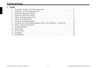
Contents<br />
1. Prior to installation . . . . . . . . . . . . . . . . . . . . . . . . . . . . . . . . . . . . . . . . . . . . . . . . . . . . . . . . . 28<br />
2. Symbols used in the installation guide . . . . . . . . . . . . . . . . . . . . . . . . . . . . . . . . . . . . . . . . . . 29<br />
3. Safety instructions . . . . . . . . . . . . . . . . . . . . . . . . . . . . . . . . . . . . . . . . . . . . . . . . . . . . . . . . . 29<br />
4. <strong>Installation</strong> instructions. . . . . . . . . . . . . . . . . . . . . . . . . . . . . . . . . . . . . . . . . . . . . . . . . . . . . . 30<br />
5. Connection diagram for the navigation system . . . . . . . . . . . . . . . . . . . . . . . . . . . . . . . . . . . 31<br />
6. <strong>Installation</strong> of the GPS antenna . . . . . . . . . . . . . . . . . . . . . . . . . . . . . . . . . . . . . . . . . . . . . . . 32<br />
7. Connecting the reverse signal. . . . . . . . . . . . . . . . . . . . . . . . . . . . . . . . . . . . . . . . . . . . . . . . .34<br />
8. Connecting the speed signal (GAL) for the speedometer / speedometer cable . . . . . . . . . . . 35<br />
9. Installing and commissioning DTM. . . . . . . . . . . . . . . . . . . . . . . . . . . . . . . . . . . . . . . . . . . . 40<br />
10. Using GPS for the first time, and sensors. . . . . . . . . . . . . . . . . . . . . . . . . . . . . . . . . . . . . . . . 40<br />
11. <strong>Installation</strong> of the Navigation Software . . . . . . . . . . . . . . . . . . . . . . . . . . . . . . . . . . . . . . . . . 42<br />
12. Calibration . . . . . . . . . . . . . . . . . . . . . . . . . . . . . . . . . . . . . . . . . . . . . . . . . . . . . . . . . . . . . . . 43<br />
13. Service Mode . . . . . . . . . . . . . . . . . . . . . . . . . . . . . . . . . . . . . . . . . . . . . . . . . . . . . . . . . . . . . 45<br />
14. Connections . . . . . . . . . . . . . . . . . . . . . . . . . . . . . . . . . . . . . . . . . . . . . . . . . . . . . . . . . . . . . . 53<br />
1. Prior to installation<br />
Before starting installation, please read this installation guide carefully. In particular, please pay attention to the safety<br />
and installation instructions.<br />
Subject to correction and technical modifications 28 Copyright by <strong>Becker</strong> <strong>GmbH</strong>, D-76303 Karlsbad
2. Symbols used in the installation guide<br />
G denotes instructions which are important for your safety and the safety of others.<br />
denotes instructions which are important for the installation and function of the unit.<br />
3. Safety instructions<br />
<strong>Installation</strong> guide<br />
G Incorrect installation<br />
Incorrect installation may result in damage to the unit or to the vehicle. Specialist knowledge and skills are required<br />
to install the unit and its components. We strongly recommend that you have the unit installed by a specialist<br />
workshop.<br />
G Risk of injury<br />
Installing the components incorrectly may lead to injuries in the event of a road traffic accident or render safety<br />
devices ineffective. Please refer to the instructions provided by the vehicle manufacturer.<br />
G Damage to the airbag<br />
Installing the components in the wrong location may damage the airbag or impair its operation. Do not install the<br />
components within the operating range of the airbag.<br />
G Risk of injury due to inadequate fastening<br />
Fix the components in place so that they cannot be loosened in the event of a collision or sudden braking.<br />
Subject to correction and technical modifications 29 Copyright by <strong>Becker</strong> <strong>GmbH</strong>, D-76303 Karlsbad
<strong>Installation</strong> guide<br />
4. <strong>Installation</strong> instructions<br />
Damage due to polarity reversal or short-circuit<br />
Incorrect cable connections and short-circuits can seriously damage the unit.<br />
Disconnect the vehicle battery before installing the unit.<br />
In order to avoid short-circuits and malfunctions, install the cables so that they cannot be pinched, kinked, chafed<br />
or detached.<br />
Before installation, park the vehicle in a safe and level place and remove the ignition key.<br />
In order to avoid malfunctions, it is absolutely essential to observe the relevant cable cross-section when using<br />
branch connections/cable connectors.<br />
In order to avoid short-circuits and any associated risk of fire, cables which have to be cut must be properly<br />
insulated.<br />
Subject to correction and technical modifications 30 Copyright by <strong>Becker</strong> <strong>GmbH</strong>, D-76303 Karlsbad
5. Connection diagram for the navigation system<br />
Radio aerial<br />
Speedometer / speedometer cable signal<br />
GPS antenna<br />
Reverse signal<br />
Power supply<br />
DTM<br />
Note: The various connection options are described in detail on page 53.<br />
<strong>Installation</strong> guide<br />
Sound system /<br />
loudspeaker<br />
Subject to correction and technical modifications 31 Copyright by <strong>Becker</strong> <strong>GmbH</strong>, D-76303 Karlsbad
<strong>Installation</strong> guide<br />
6. <strong>Installation</strong> of the GPS antenna<br />
G Risk of injury<br />
People with pacemakers should avoid physical contact with the magnetic antenna and should not carry the antenna<br />
on their person, as this may affect the function of the pacemaker.<br />
Keep the magnetic antenna away from data storage media (disks, credit cards, magnetic cards etc.) and electronic<br />
and precision engineering equipment, as this may cause data to be deleted.<br />
Do not use the antenna in areas at risk of explosion.<br />
It is important to secure the antenna so that it cannot become detached in a collision or sudden brake manoeuvre.<br />
Possible installation positions<br />
• Outside the vehicle<br />
a. Attach the antenna to a flat, pre-washed metal surface.<br />
b. Then guide the antenna cable into the vehicle interior.<br />
G Risk of injury<br />
The maximum vehicle speed for the antenna if magnetically attached is 180 km/h. The antenna must be removed or<br />
specially secured at higher speeds.<br />
The antenna is not suitable for car-wash facilities.<br />
Subject to correction and technical modifications 32 Copyright by <strong>Becker</strong> <strong>GmbH</strong>, D-76303 Karlsbad
• Inside the vehicle<br />
<strong>Installation</strong> guide<br />
The antenna can only be installed on a non-metallised windscreen.<br />
When selecting the installation position, ensure that the antenna has a clear view of all directions, and that it is not<br />
covered by the windscreen wipers. Obstructions caused by the bonnet, window crossbeams and roof should be<br />
avoided as far as possible.<br />
a. Secure the antenna to the base plate (1) with magnets.<br />
b. Remove protective strip from top of adhesive tape (2) and stick to the centre of the base plate underside.<br />
c. Remove protective strip from bottom of adhesive tape (2) and stick the antenna and base plate onto the vehicle<br />
console beneath the windscreen at the installation position.<br />
Subject to correction and technical modifications 33 Copyright by <strong>Becker</strong> <strong>GmbH</strong>, D-76303 Karlsbad
<strong>Installation</strong> guide<br />
GPS reception can be affected by screens with screen antenna, windscreen heating or thermally insulated screens.<br />
Some thermally insulated screens are coated with titanium or silver oxide. <strong>Installation</strong> of the GPS antenna in the<br />
vehicle interior can considerably impair the function of the navigation system.<br />
7. Connecting the reverse signal<br />
The pick-up points for the reverse signal vary from vehicle to vehicle.<br />
If you are in any doubt, please contact your vehicle manufacturer or authorised specialist workshop.<br />
If the switch on the gearbox or shift linkage is accessible:<br />
• Connect a separate lead to the activated contact.<br />
Connect the lead to socket A pin 2.<br />
Low - level = earth, high - level 12 V - 16 V<br />
If the switch is not accessible:<br />
• Check which lead is routed to the reversing lamp. Then, if necessary,<br />
remove the inner cover for the reversing light.<br />
Connect a separate lead to the activated lead of the reversing lamp<br />
and connect to socket A pin 2.<br />
Reverse<br />
signal<br />
Subject to correction and technical modifications 34 Copyright by <strong>Becker</strong> <strong>GmbH</strong>, D-76303 Karlsbad<br />
A
8. Connecting the speed signal (GAL) for the speedometer / speedometer cable<br />
<strong>Installation</strong> guide<br />
G Accident hazard<br />
Incorrectly connected wiring may result in damage to or destruction of vehicle components and safety devices.<br />
If you are in any doubt, please contact your vehicle manufacturer or authorised specialist workshop.<br />
Electronic speedometer<br />
• Remove the signal from the speedometer, extend and connect to<br />
socket A pin 1.<br />
Depending on the vehicle equipment, the lead for the GAL signal<br />
is usually connected to the DIN - ISO plug of the car radio.<br />
The assignment of the DIN - ISO plug may vary depending on<br />
the vehicle type.<br />
• Minimum requirement for the signal:<br />
0 Hz - 4 kHz / square-wave signal (no inductive sensor)<br />
Low - level < 1.5 V, high - level 5 V - 16 V<br />
If you do not know the exact installation position / location of<br />
the speed signal, please consult the vehicle manufacturer.<br />
GAL signal<br />
Subject to correction and technical modifications 35 Copyright by <strong>Becker</strong> <strong>GmbH</strong>, D-76303 Karlsbad<br />
A
<strong>Installation</strong> guide<br />
Mechanical speedometer with integrated speed sensor in the speedometer cable<br />
• Remove the signal from the speed sensor, extend and connect to<br />
socket A pin 1.<br />
• Minimum requirement for the signal:<br />
0 Hz - 4 kHz / square-wave signal (no inductive sensor)<br />
Low - level < 1.5 V, high - level 5 V - 16 V<br />
If you do not know the exact installation position / location of<br />
the speed signal, please consult the vehicle manufacturer.<br />
Mechanical speedometer without speed sensor in the speedometer cable<br />
A speed sensor which generates a digital, speed-dependent signal must<br />
be installed in the speedometer cable.<br />
The VDO adapter 2152.30300000 or a vehicle-specific adapter which<br />
satisfies the minimum requirements can be used. The VDO speed sensor<br />
is suitable for direct installation on the gearbox (no further installation<br />
parts required) or in the speedometer cable (in conjunction with<br />
additional universal installation parts).<br />
If the sealed speedometer cable is released, a correct display<br />
cannot be guaranteed. Incorrect installation leads to improper<br />
functioning of the navigation system or of the speedometer.<br />
GAL signal<br />
Subject to correction and technical modifications 36 Copyright by <strong>Becker</strong> <strong>GmbH</strong>, D-76303 Karlsbad<br />
A
Installing the speed sensor directly on the gearbox<br />
• Release the speedometer cable and screw speed sensor onto gearbox.<br />
Screw released speedometer cable onto the speed sensor and<br />
connect the wires.<br />
Wire connections for the speed sensor<br />
Brown - earth (terminal 31)<br />
Black - power supply (terminal 15), 9 - 16V, 30 mA<br />
Blue/red - signal for socket A pin 1<br />
Installing the speed sensor in the speedometer cable<br />
In order to install the speed sensor, the speedometer drive cable must be<br />
cut in one even piece for insertion of the speed sensor. When removing<br />
the speedometer cable from the vehicle, ensure that the location of the<br />
evenly running piece is established and marked accordingly.<br />
<strong>Installation</strong> is illustrated without reference to any specific vehicle. In<br />
addition to the sensor, the following VDO universal parts are required:<br />
1 x connecting piece 1040 1300 025 (VDO part number)<br />
2 x knurled nuts1 040 1000 003 (VDO part number)<br />
2 x hose sleeves 1040 1000 031 (VDO part number)<br />
2 x dogs1 040 1000 049 (VDO part number)<br />
2 x friction washers 1040 0900 003 300 (VDO part number)<br />
2 x fuel washers 4.0 KN07.0570.18 (VDO part number)<br />
2 x washers KN11.1904.122 (VDO part number)<br />
An appropriate, complete kit from VDO (part number X 39397106191)<br />
can also be used.<br />
<strong>Installation</strong> guide<br />
GAL signal<br />
Subject to correction and technical modifications 37 Copyright by <strong>Becker</strong> <strong>GmbH</strong>, D-76303 Karlsbad<br />
A<br />
Figure 1
<strong>Installation</strong> guide<br />
Recommended tool: Cable installation tool for speedometer cables<br />
from VDO, order number: 1999.10.13.000.110<br />
If you require vehicle-specific parts, please consult the vehicle manufacturer<br />
or your nearest VDO branch.<br />
• Using a metal saw, saw into the cable approx. 1 mm at right angles<br />
to the profile and break off (Figure 3).<br />
• Then cut the cable in the centre with side-cutting pliers<br />
(Figure 4).<br />
For protective hoses with wire netting, the hose and flex cable<br />
can be cut directly with the side-cutting pliers.<br />
• Shorten the protective hose again at both ends up to the plastic<br />
sheathing. Check whether the ends of the flex cable still engage in<br />
the speedometer and the gearbox.<br />
• Shorten the inner cable to a projection of 13 mm (Figure 5).<br />
• Connect the union nut and hose sleeve (Figure 6) and push onto the<br />
hose ends (Figure 7).<br />
• Connect friction washer to dog (Figure 8).<br />
Figure 5<br />
Figure 4<br />
Figure 8<br />
Figure 6<br />
Figure 7<br />
Figure 3<br />
Subject to correction and technical modifications 38 Copyright by <strong>Becker</strong> <strong>GmbH</strong>, D-76303 Karlsbad
• Remove grease from flex cable and connect dog to flex cable. Using<br />
a suitable installation tool, press the dog onto the flex cable<br />
(Figure 9).<br />
When pressing in, ensure that the dog is securely positioned and<br />
that it runs smoothly.<br />
• Pull the hose sleeve and nut as far as possible in the direction of the<br />
dog, to achieve approx. 1-2 mm play (Figure 10).<br />
Slightly squeeze the hose sleeve with pliers. Wrap with isolating<br />
tape to secure (Figure 11).<br />
• Screw the connecting piece and the speed sensor into the cable<br />
(Figure 12).<br />
• Connect speed sensor using the extension cable from VDO (part<br />
number: 2152.90 30 0100).<br />
Wire connections for the speed sensor<br />
Brown - earth (terminal 31)<br />
Black - power supply (terminal 15), 9 - 16V, 30 mA<br />
Blue/red - signal for socket A pin 1<br />
Figure 9<br />
Figure 10<br />
Figure 12<br />
<strong>Installation</strong> guide<br />
Figure 11<br />
Subject to correction and technical modifications 39 Copyright by <strong>Becker</strong> <strong>GmbH</strong>, D-76303 Karlsbad
<strong>Installation</strong> guide<br />
9. Installing and commissioning DTM<br />
• This navigation system has an integrated universal bracket for DIN installation slots. An installation frame is not required.<br />
The unit is inserted into the installation slot and secured with the slides supplied.<br />
Further information is given in the operation guide in the chapter, "<strong>Installation</strong> and removal instructions".<br />
The installation angle of the unit must not exceed -10° to 35° (vertical).<br />
• Connect the battery.<br />
10. Using GPS for the first time, and sensors<br />
• Switch on the vehicle ignition to start using GPS for the first time<br />
and for the sensor test. Switch on DTM.<br />
Enter code (see the operation guide for a detailed description).<br />
• Press the multifunction button and the multifunction<br />
button simultaneously.<br />
• This calls up the menu for the initial GPS start-up and for the sensor<br />
test.<br />
• Move the vehicle several metres forwards or backwards for the<br />
speed signal function test.<br />
The number under 7,,+ must change (even at a low speed).<br />
The number under 7,,+ should not increase when idling or<br />
pressing the accelerator when the vehicle is parked.<br />
P Y<br />
5; +; ,� 79 >9 SM<br />
7,,+ 09,*;065<br />
VVV<br />
7,,+ 09,*;065<br />
VMN<br />
$ !<br />
P P<br />
P<br />
$ !<br />
P P<br />
P<br />
$ !<br />
P P<br />
P<br />
Subject to correction and technical modifications 40 Copyright by <strong>Becker</strong> <strong>GmbH</strong>, D-76303 Karlsbad
• Engage the reverse gear for the reverse signal function test.<br />
The arrows under 09,*;065 must change direction on engaging<br />
the reverse gear.<br />
• When using the GPS for the first time, the vehicle must be parked<br />
outdoors, while ensuring that it has a clear view in all directions<br />
(not in the immediate vicinity of buildings).<br />
Information on the GPS reception is given in the right-hand part of<br />
the display.<br />
Four different messages may appear:<br />
- : GPS reception is already available.<br />
- $ !: It is necessary to wait for GPS reception. You must<br />
wait until GPS OK is displayed.<br />
- ! : The GPS antenna is not properly connected.<br />
- " : If this message is displayed, please contact<br />
the hotline.<br />
7,,+ 09,*;065<br />
VVV<br />
7,,+ 09,*;065<br />
VMN<br />
7,,+ 09,*;065<br />
VMN<br />
7,,+ 09,*;065<br />
VMN<br />
7,,+ 09,*;065<br />
VMN<br />
<strong>Installation</strong> guide<br />
$ !<br />
P P<br />
P<br />
P P<br />
P<br />
$ !<br />
P P<br />
P<br />
You must wait until , P (or P ) and P (or a higher value) is displayed.<br />
This procedure (first reception of the necessary GPS data) may take a few minutes. The unit must remain<br />
switched on for the entire duration of this procedure. The vehicle must not be moved. If after 5 minutes there has<br />
been no change in the values, the parked position (clear view in all directions as far as possible) or the installation<br />
location of the GPS antenna must be checked.<br />
Subject to correction and technical modifications 41 Copyright by <strong>Becker</strong> <strong>GmbH</strong>, D-76303 Karlsbad<br />
!<br />
"
<strong>Installation</strong> guide<br />
• The menu for initial GPS start-up and for the sensor test is quit by<br />
simultaneously pressing the multifunction button and the<br />
multifunction button.<br />
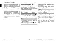
11. <strong>Installation</strong> of the Navigation Software<br />
• Press the 1$9 button.<br />
• Insert the Navigation CD to install the software for the navigation<br />
system.<br />
• After the navigation software has been installed, the adjacent display<br />
appears. The language selection is then requested.<br />
• Select the language using the right rotary control . The language<br />
selection is accepted by pressing the control.<br />
You can choose either a male or a female voice for some languages.<br />
Select the voice using the right rotary control . The voice is accepted<br />
and installed by pressing the control.<br />
The adjacent display appears after installation. Then press the right<br />
rotary control to confirm.<br />
The language selection can be changed at a later time, as described<br />
in the operating guide.<br />
7,,+ 09,*;065<br />
VMN<br />
P P<br />
P<br />
# ! ! # ! B<br />
# !<br />
Subject to correction and technical modifications 42 Copyright by <strong>Becker</strong> <strong>GmbH</strong>, D-76303 Karlsbad<br />
"<br />
M
12. Calibration<br />
After commissioning, a calibration journey is required. During the journey,<br />
the speed signal (GAL) is automatically adapted to the<br />
vehicle-specific data and the gyro sensor is automatically adapted<br />
to the installation position of the unit.<br />
The distance to be covered depends on the type of vehicle and the local<br />
conditions.<br />
The navigation system is only ready for operation on completion<br />
of the calibration journey. The main navigation menu is<br />
displayed. Final precision is only achieved after a further journey.<br />
• The adjacent display appears after the language installation.<br />
It is possible that GPS reception has deteriorated as a result of<br />
changing the vehicle position and due to obstructions. In this case,<br />
the adjacent display appears.<br />
Adequate GPS reception must be ensured for the calibration<br />
ride. This means at least 2-D FIX. With GPS FIX 3-D the calibration<br />
will be quicker. However: a lower accuracy of the GPS<br />
signal (2-D FIX) does not lead to a poorer calibration, but instead<br />
will mean that the time and distance needed for the calibration<br />
will increase.<br />
<strong>Installation</strong> guide<br />
! ! !<br />
$ P N & P N !P<br />
P Y P Y<br />
$ ! ! B<br />
! !<br />
Y Y P \ %<br />
Subject to correction and technical modifications 43 Copyright by <strong>Becker</strong> <strong>GmbH</strong>, D-76303 Karlsbad
<strong>Installation</strong> guide<br />
If, even after a relatively long period of time, the display with the request<br />
! ! ! does not appear,<br />
then you should check the GPS reception conditions again (as under<br />
Service Mode in the Section Function test of GPS antenna (<br />
)46).<br />
As soon as the display with the request !<br />
! ! appears, the calibration ride can be started.<br />
A calibration ride can also be performed in a non-digitised area.<br />
The insertion of the Navigation CD is not absolutely necessary<br />
after the navigation software has been installed. Without the<br />
Navigation CD inserted, no location is displayed.<br />
• The basic requirement for a calibration ride is: driving 200 - 300<br />
metres in a straight line, then turning by at least 60 degrees<br />
and then driving 200- 300 metres in a straight line again, and<br />
turning again.<br />
The direction you turn is of no significance. If these conditions<br />
cannot be fulfilled due to the road or the fact that you do not always<br />
have optimum GPS reception, this will not lead to a poorer<br />
calibration, but will simply mean the time and distance<br />
necessary for the calibration ride will be longer.<br />
If the unit is switched off during the calibration ride, language<br />
installation is requested when the unit is switched on again. Reinstallation<br />
can be skipped by pressing the 1$9<br />
button.<br />
Subject to correction and technical modifications 44 Copyright by <strong>Becker</strong> <strong>GmbH</strong>, D-76303 Karlsbad
• Calibration has been completed successfully if the main navigation<br />
menu is displayed.<br />
• For correct navigation on routes with time-dependent traffic guidance,<br />
the time should be set correctly as described under "System<br />
settings" in the operation guide.<br />
13. Service Mode<br />
In Service Mode, various functions can be checked in detail and the calibration<br />
can be modified.<br />
• Switch on the unit (see operation guide).<br />
Enter code (see operation guide).<br />
• If the unit has already been calibrated, select the main navigation<br />
menu by pressing the 1$9 button.<br />
If the unit has not been calibrated, proceed as described in the next<br />
point but one.<br />
• Press the 1$9 button again to access the system settings.<br />
• Press and hold the multifunction buttons. Then press the<br />
multifunction button. This calls up the Service Mode.<br />
!Y &<br />
<strong>Installation</strong> guide<br />
Subject to correction and technical modifications 45 Copyright by <strong>Becker</strong> <strong>GmbH</strong>, D-76303 Karlsbad<br />
Y Y Y<br />
!Y &<br />
Y Y Y<br />
! F
<strong>Installation</strong> guide<br />
The following functions can be selected in the Service Mode:<br />
• - GPS function test<br />
• ! - function for deleting the calibration or for setting<br />
a calibration<br />
• ! - display for calibration ride<br />
• " ! ! - internal component test<br />
• - sensor function test<br />
• ! ! - voice test<br />
• - demo mode selection<br />
• # - the status of the Navigation CD is displayed<br />
By turning the right rotary control , select the desired entry<br />
(large letters) and press to confirm.<br />
Function test of GPS antenna ( )<br />
In Service Mode, select S with the right rotary control and<br />
press to confirm.<br />
If functioning properly and with GPS reception, the number of satellites<br />
received (e.g. ), the date and time (e.g. Y Y P P ) and the<br />
type of positioning currently possible %P (e.g. ) are displayed.<br />
At least % is required for quick and successful calibration.<br />
A certain amount of time may be required to reach this value<br />
(do not move the vehicle during this period).<br />
In order to quit the GPS test, press the<br />
back to the Service Mode.<br />
1$9<br />
button. The unit switches<br />
Subject to correction and technical modifications 46 Copyright by <strong>Becker</strong> <strong>GmbH</strong>, D-76303 Karlsbad<br />
#<br />
#<br />
!<br />
!<br />
P P P P<br />
% %P<br />
Y &P
Changing the calibration ( ! )<br />
Deleting the calibration:<br />
If the navigation system is removed from one vehicle and installed in<br />
another, it must be calibrated. However, to do so, the current calibration<br />
data must be deleted.<br />
In the Service Mode, select ! using the right rotary<br />
control and press to confirm.<br />
Using the right rotary control select ! and press to confirm.<br />
The calibration is deleted and the unit returns to the Service Mode.<br />
Calibration setting:<br />
Calibration settings should only be made when the values to be<br />
entered are known. The unit cannot perform correct route calculations<br />
if incorrect values are entered.<br />
It is possible to provide calibration settings.<br />
In the Service Mode, select ! using the right rotary<br />
control and press to confirm.<br />
Using the right rotary control select & and press to confirm.<br />
Unit rotation can be selected in degrees by turning the right rotary<br />
control and pressing to confirm.<br />
<strong>Installation</strong> guide<br />
Subject to correction and technical modifications 47 Copyright by <strong>Becker</strong> <strong>GmbH</strong>, D-76303 Karlsbad<br />
!<br />
!<br />
! !<br />
&<br />
!<br />
! !<br />
' ! " ! ! !
<strong>Installation</strong> guide<br />
Unit rotation corresponds to horizontal rotation. A positive value<br />
means rotation of the front of the unit towards the driver<br />
(LHD).<br />
The unit inclination can now be selected in degrees by turning the right<br />
rotary control and pressing to confirm.<br />
Unit inclination corresponds to vertical inclination. A positive<br />
value means upward inclination of the front of the unit.<br />
The number of wheel impulses per wheel revolution (if known) can then<br />
be selected by turning the right rotary control and pressing to confirm.<br />
If the number of wheel impulses per wheel revolution is not<br />
known, " $ must be selected. It is then not possible to enter<br />
tyre data.<br />
The previously entered data is displayed once more. If the data entered<br />
is correct, press the right rotary control .<br />
If correction is necessary, select & by turning the right rotary<br />
control and press to confirm. The values can then be re-entered.<br />
Once the previously entered data has been confirmed, the tyre data can<br />
be entered or self-calibration can be started.<br />
To enter the tyre data, select "! !& # " by turning the<br />
right rotary control and press to confirm.<br />
" ! !<br />
$ "<br />
" $<br />
E<br />
&<br />
V E NQ EPT<br />
D<br />
"! !& # "<br />
Subject to correction and technical modifications 48 Copyright by <strong>Becker</strong> <strong>GmbH</strong>, D-76303 Karlsbad
Enter the correct tyre size using the right rotary control and confirm the<br />
entry by pressing for more than 2 seconds.<br />
The letter "R" cannot be entered. 3 numbers must be entered before<br />
and after the slashes. Insert a "0" for any missing numbers.<br />
Example:<br />
Specification in vehicle registration papers: 185/55R15 81T<br />
Input into unit: 185/055/015<br />
Then select between $ !& ! and " !& ! by<br />
turning the right rotary control to enter the approximate tread depth<br />
value.<br />
Press the right rotary control to confirm the selection.<br />
The previously entered data is displayed once more. If the data entered<br />
is correct, press the right rotary control .<br />
If correction is necessary, select & by turning the right rotary<br />
control and press to confirm. The values can then be re-entered.<br />
After confirming the tyre data or the previously confirmed point ! !<br />
! , the adjacent display appears.<br />
After a short time, the unit switches to the main navigation menu or the<br />
calibration ride is requested.<br />
The unit is now in calibration status 2. Absolute precision is,<br />
however, only achieved as of calibration status 3.<br />
"! !& P<br />
!& ' TTTFTTTFTTT<br />
<strong>Installation</strong> guide<br />
GLQ H<br />
" !& ! GLJ H<br />
MTQYVQQYVMQN<br />
Subject to correction and technical modifications 49 Copyright by <strong>Becker</strong> <strong>GmbH</strong>, D-76303 Karlsbad<br />
"!<br />
&
<strong>Installation</strong> guide<br />
Status of calibration ride ( ! )<br />
In the Service Mode, select ! using the right rotary<br />
control and press to confirm.<br />
The calibration status (e.g. ! ! P ) and the type of positioning (e.g.<br />
) are displayed. After completing calibration, the street in which you<br />
are currently driving is displayed (provided that it is digitised) instead<br />
of $ and #Y.<br />
Testing the system components ( " ! !)<br />
A test program automatically tests the internal components of the navigation<br />
system.<br />
In the Service Mode, select " ! ! using the right rotary<br />
control and press to confirm.<br />
If is displayed, press the 1$9 button. The unit switches back to<br />
the Service Mode.<br />
Function test of the GAL signal, reverse signal, internal sensors<br />
( )<br />
• In the Service Mode, select using the right rotary<br />
control and press to confirm.<br />
• Move the vehicle several metres forwards or backwards for the<br />
GAL signal function test.<br />
The number after $ P should increase (even at a low<br />
speed).<br />
The number after $ P should not increase if idling or pressing<br />
the accelerator when the vehicle is parked.<br />
Subject to correction and technical modifications 50 Copyright by <strong>Becker</strong> <strong>GmbH</strong>, D-76303 Karlsbad<br />
!<br />
" ! !<br />
! ! P S %<br />
! !<br />
P Y P Y<br />
!<br />
" ! !<br />
! !<br />
$ P #YP<br />
& P<br />
%P S &P S
• Engage the reverse gear for the reverse signal function test.<br />
The number after #YP should jump from to ( to ).<br />
• Drive round a bend to test the function of the internal sensors.<br />
The values after %P and &P should change.<br />
In order to quit the sensor test, press the<br />
switches back to the Service Mode.<br />
1$9 button. The unit<br />
Testing the voice ( ! !)<br />
A test program is used to test the voice.<br />
• In the Service Mode, select ! ! using the right rotary<br />
control and press to confirm.<br />
The announcement "Please insert Navigation CD" is given.<br />
By pressing the right rotary control<br />
repeated.<br />
, the announcement can be<br />
After completing the test, press the<br />
switches back to the Service Mode.<br />
1$9<br />
button. The unit<br />
<strong>Installation</strong> guide<br />
Subject to correction and technical modifications 51 Copyright by <strong>Becker</strong> <strong>GmbH</strong>, D-76303 Karlsbad
<strong>Installation</strong> guide<br />
Demo Mode ( )<br />
The demo mode is intended for demonstration purposes. A fixed location<br />
is given to the unit (Hamburg Werderstaße).<br />
• In the Service Mode, select S using the right rotary<br />
control and press to confirm.<br />
Select between and by briefly pressing the right rotary<br />
control . By holding down the right rotary control , the selection<br />
is confirmed.<br />
• You can now enter a destination as described in the operation<br />
guide.<br />
• To switch off the demo mode, select with the right rotary<br />
control and press to confirm.<br />
Subject to correction and technical modifications 52 Copyright by <strong>Becker</strong> <strong>GmbH</strong>, D-76303 Karlsbad<br />
#<br />
! !<br />
S F
14. Connections<br />
Antenna<br />
bushing<br />
Socket A<br />
1 Speed signal (GAL)<br />
2 Reversing lamp signal<br />
3 Telephone mute / clearing function<br />
4 Permanent positive (terminal 30)<br />
5 Control output for automatic antenna/amplifier<br />
6 Illumination (terminal 58)<br />
7 Switched positive (terminal 15)<br />
8 Earth (terminal 31)<br />
Socket B<br />
1 Loudspeaker rear right +<br />
2 Loudspeaker rear right -<br />
3 Loudspeaker front right +<br />
4 Loudspeaker front right -<br />
5 Loudspeaker front left +<br />
6 Loudspeaker front left -<br />
7 Loudspeaker rear left +<br />
8 Loudspeaker rear left -<br />
C1 C2 C3<br />
<strong>Installation</strong> guide<br />
GPS<br />
antenna<br />
Socket C1<br />
1 LineOut rear left<br />
2 LineOut rear right<br />
3 AF earth<br />
4 LineOut front left<br />
5 LineOut front right<br />
6 Subwoofer LineOut<br />
Socket C2<br />
7-12 Special connection for <strong>Becker</strong> CD changer<br />
Socket C3<br />
13 AF telephone input<br />
14 Earth - telephone input<br />
15-17 Special connection for <strong>Becker</strong> CD changer<br />
18 CD AF earth (AUX)<br />
19 CD AF left (AUX)<br />
20 CD AF right (AUX)<br />
Subject to correction and technical modifications 53 Copyright by <strong>Becker</strong> <strong>GmbH</strong>, D-76303 Karlsbad<br />
B<br />
A