

Valtek ChannelStream Control Valves.pdf - PRO-QUIP
Valtek ChannelStream Control Valves.pdf - PRO-QUIP
Valtek ChannelStream Control Valves.pdf - PRO-QUIP

You also want an ePaper? Increase the reach of your titles
YUMPU automatically turns print PDFs into web optimized ePapers that Google loves.
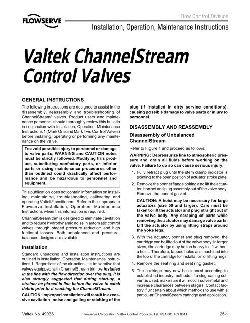
<strong>Valtek</strong> <strong>ChannelStream</strong><strong>Control</strong> <strong>Valves</strong>GENERAL INSTRUCTIONSThe following instructions are designed to assist in thedisassembly, reassembly and troubleshooting of<strong>ChannelStream</strong> ® valves. Product users and maintenancepersonnel should thoroughly review this bulletinin conjunction with Installation, Operation, MaintenanceInstructions 1 (Mark One and Mark Two <strong>Control</strong> <strong>Valves</strong>)before installing, operating or performing any maintenanceon the valve.To avoid possible injury to personnel or damageto valve parts, WARNING and CAUTION notesmust be strictly followed. Modifying this product,substituting nonfactory parts, or inferiorparts or using maintenance procedures otherthan outlined could drastically affect performanceand be hazardous to personnel andequipment.This publication does not contain information on installing,maintaining, troubleshooting, calibrating andoperating <strong>Valtek</strong> ® positioners. Refer to the appropriateFlowserve Installation, Operation, MaintenanceInstructions when this information is required.<strong>ChannelStream</strong> trim is designed to eliminate cavitationand to reduce hydrodynamic noise in automatic controlvalves through staged pressure reduction and highfrictional losses. Both unbalanced and pressurebalanceddesigns are available.InstallationStandard unpacking and installation instructions areoutlined in Installation, Operation, Maintenance Instructions1. Regardless of the air-action, it is imperative thatvalves equipped with <strong>ChannelStream</strong> trim be installedin the line with the flow direction over the plug. It isalso strongly suggested that during start-up, astrainer be placed in line before the valve to catchdebris prior to it reaching the <strong>ChannelStream</strong>.CAUTION: Improper installation will result in excessivecavitation, noise and galling or sticking of theplug (if installed in dirty service conditions),causing possible damage to valve parts or injury topersonnel.DISASSEMBLY AND REASSEMBLYDisassembly of Unbalanced<strong>ChannelStream</strong>Refer to Figure 1 and proceed as follows:WARNING: Depressurize line to atmospheric pressureand drain all fluids before working on thevalve. Failure to do so can cause serious injury.1. Fully retract plug until the stem clamp indicator ispointing to the open position of actuator stroke plate.2. Remove the bonnet flange bolting and lift the actuator,bonnet and plug assembly out of the valve body.Remove the bonnet gasket.CAUTION: A hoist may be necessary for largeactuators (size 50 and larger). Care must betaken to lift the actuator and plug straight out ofthe valve body. Any scraping of parts whileremoving the actuator may damage valve parts.Lift the actuator by using lifting straps aroundthe yoke legs.3. With the actuator, bonnet and plug removed, thecartridge can be lifted out of the valve body. In largersizes, the cartridge may be too heavy to lift withouta hoist. Therefore, tapped holes are machined intothe top of the cartridge for installation of lifting rings.4. Remove the seat ring and seat ring gasket.5. The cartridge may now be cleaned according toestablished industry methods. If a degreasing solventis used, make sure it will not dissolve metal andincrease clearances between stages. Contact factoryif uncertain about which methods to use with aparticular <strong>ChannelStream</strong> cartridge and application.<strong>Valtek</strong> No. 49036 Flowserve Corporation, <strong>Valtek</strong> <strong>Control</strong> Products, Tel. USA 801 489 861125-1
Bonnet(Item No. 40)BonnetFlangeBolting(Item No. 108/114)BonnetGasket(Item No. 58)Plug(Item No. 50)BonnetFlange(Item No. 70)Channel-StreamCartridge(Item No. 30)Seat Ring(Item No. 20)Seat RingGasket(Item No. 20)Bonnet(Item No. 40)SleeveGasket(Item No. 56)Sleeve(Item No. 31)Plug Seals(Item No. 65)Plug(Item No. 50)Plug VentBody(Item No. 1)Bonnet FlangeBolting(Item No. 108/114)BonnetFlange(Item No. 70)BonnetGasket(Item No. 58)<strong>ChannelStream</strong>Cartridge(Item No. 30)Seat Ring(Item No. 20)FLOWFLOWBody(Item No. 1)Figure 1: Unbalanced TrimSeat RingGasket(Item No. 55)Figure 2: Pressure-balanced TrimNOTE: Item numbers refer to the valve's bill of material. Refer to it for specific part numbers.NOTE: If cartridge must be disassembled to cleanindividual channels and expansion holes, carefullygrind away the small bead welds located near thetop of the cartridge. This will loosen pins located incounter-drilled holes. The pins can now beremoved and the stages separated.WARNING: To avoid personal injury, use eyeand face protection when grinding or usingsolvents.Reassembly of Unbalanced <strong>ChannelStream</strong>Refer to Figure 1 and proceed as follows:1. If the cartridge has been disassembled for cleaning,realign vent holes at the top of retainer and replacepins. Pins should be placed 180 degrees from eachother and tack welded using a 1 /8-inch bead weld toretain the pin.Caution: Do not weld any more than the approved1 /2 inch. Excessive heat from bead weldsthat are too large can disturb critical plug /cartridge tolerances. Use an appropriate weldrod which is compatible with the cartridgematerial (if uncertain, contact factory).2. Install a new seat ring gasket and reinstall seat ring.NOTE: Bonnet and seat ring gaskets should bereplaced every time the valve is disassembled.3. Install the cleaned cartridge, making sure the endwith pins is at the top (toward the bonnet). Visuallyposition the cartridge concentric with seat ring bore.4. Install a new bonnet gasket.5. Fully retract plug (stem clamp indicator pointing tothe open position) and lower actuator, bonnet andplug squarely into body and cartridge.WARNING: Failure to return plug to mid-strokeposition on mechanical / hydraulic actuatorswill cause damage to actuator and / or valveduring bonnet tightening sequence. This is dueto the inability of most mechanical / hydraulicactuators to accommodate the 1 /16-inch backdrivingduring tightening sequence.CAUTION: The bonnet aligns closely to thebody and the plug aligns closely with the cartridge;therefore, caution should be used tomake sure they are installed squarely.6. Once bonnet is resting on the body, tighten bonnetflange bolting to finger-tightness.7. Seat the plug two or three times to center the seatring. This is done by applying air to the actuator.NOTE: Step 8 applies only to valves with pneumaticactuators. If a hydraulic or mechanical operator isused, leave the plug in mid-stroke and proceed tostep 9.25-2 Flowserve Corporation, <strong>Valtek</strong> <strong>Control</strong> Products, Tel. USA 801 489 8611
8. With plug in the extended (or closed) position, begintightening bonnet flange bolting (keep the bonnetsquare with the valve). Tighten the first bolt 1 /6 turn,then tighten the bolt directly opposite 1 /6 turn.9. Continue tightening all bolts until the bonnet isfirmly seated, metal-to-metal, in the body. This caneasily be felt through the wrench.10. Slowly stroke the plug up and down to check thealignment of the plug with the cartridge.CAUTION: If erratic jerking of stroke indicatoror scraping is detected, stop stroking the valveimmediately. This may indicate misalignment.Remove the bonnet and actuator and realignthe cartridge by repeating steps 3 through 10 ofthis section. If either or both the plug orcartridge bore are damaged, consult factory.Disassembly of Pressure-balanced<strong>ChannelStream</strong>Refer to Figure 2 and proceed as follows:WARNING: Depressurize line to atmospheric pressureand drain all fluids before working on thevalve. Failure to do so can cause serious injury.1. Fully retract plug until stem clamp indicator is pointingto open position.2. Remove bonnet flange bolting and lift actuator,bonnet and plug out of valve body. A hoist may benecessary for larger valves.WARNING: Danger exists in removing actuator,bonnet and plug – especially if PTFE pressurebalancedseals are used. The pressurebalancedsleeve may stick to the plug and fallduring disassembly, causing possible seriousinjury and / or damage to the valve or nearbyequipment. Steps 3 through 6 should be consultedbefore attempting to remove the plug fromthe sleeve.3. If the sleeve is observed sticking to the plug duringremoval, do not attempt to lift plug and sleeve out ofthe body.4. Fully extend the plug, allowing the bonnet to riseabove the body.5. Place equally thick, wooden blocks in at least threeplaces between the sleeve and bonnet. Retractplug until seals are freed from sleeve.6. Lift actuator, bonnet and plug assembly from body,taking care not to damage sleeve bore of plug head.7. Remove the sleeve, cartridge, seat ring and gasketsfrom body. In larger sizes, the cartridge orsleeve may be too heavy to lift without a hoist.Therefore, tapped holes are machined into the topof cartridge and sleeve for installation of lifting rings.8. The cartridge may now be cleaned according toestablished industry methods. If a degreasingsolvent is used, make sure it will not dissolve metaland increase the tolerances between stages. Contactthe factory if uncertain about which methods touse with a particular <strong>ChannelStream</strong> cartridge andapplication.NOTE: If the cartridge must be disassembled toclean the individual channels and expansion holes,carefully grind away small bead welds located nearthe top of the cartridge. This will loosen pins locatedin counter-drilled holes. The pins can now be removedand the stages separated.Reassembly of Pressure-balanced<strong>ChannelStream</strong>Refer to Figure 2 and proceed as follows:1. If the cartridge has been disassembled for cleaning,realign vent holes at top of retainer and replacepins. Pins should be placed 180 degrees from eachother. The pins must then be tack welded using a1/8-inch bead weld to retain the pin.CAUTION: Do not weld any more than the approved1 /8 inch. Excessive heat from bead weldsthat are too large can disturb critical plug /cartridge tolerances. Use an appropriate weldrod which is compatible with the cartridge material(if uncertain, contact factory).2. Install new seat gasket and reinstall seat ring.NOTE: All gaskets should be replaced wheneverthe valve is disassembled.3. Install new bonnet and sleeve gaskets. Installcartridge and sleeve. Use lifting rings and hoistwhen installing cartridges and sleeves machinedwith tapped holes.4. Lower actuator, bonnet and plug assemblysquarely into sleeve bore. If PTFE seals are used,the plug may remain retracted. Care should betaken with PTFE seals to avoid scoring or gallingsealing surfaces while fitting the plug into the sleevebore. With metal piston ring seals, the plug must beextended a few inches to allow the use of a ringcompressor on metal rings. A suitable sized screwtypehose clamp will also serve to compress therings for reassembly.WARNING: Failure to return plug to mid-strokeposition on mechanical / hydraulic actuatorswill cause damage to actuator and / or valveduring the bonnet tightening sequence. This isdue to the inability of most mechanical / hydraulicactuators to accommodate the 1 /16-inchback-driving during tightening sequence.5. Once the bonnet is resting on the body, reinstall andtighten bonnet flange bolting to finger-tightness.6. Seat the plug two or three times to center the seatring. This can be done using the actuator.Flowserve Corporation, <strong>Valtek</strong> <strong>Control</strong> Products, Tel. USA 801 489 861125-3
NOTE: Step 7 applies only to valves with pneumaticactuators. If a hydraulic or mechanical operator isused, leave plug in mid-stroke and proceed to step 8.7. With the plug in the extended (or closed) position,begin tightening bonnet flange bolting. (Keep thebonnet square with the valve.) Tighten the first bolt1/6 turn, then tighten the bolt directly opposite 1 /6 turn.8. Continue tightening all bolting until bonnet is firmlyseated, metal to metal, in the body.Troubleshooting <strong>ChannelStream</strong> <strong>Control</strong> <strong>Valves</strong>Problem Probable Cause Corrective Action9. Slowly stroke the plug up and down to checkalignment of plug with the cartridge.CAUTION: If erratic jerking of the stroke indicatoris detected, stop stroking the valve immediately.This may indicate misalignment. Removebonnet and actuator and realign the cartridgeby repeating steps 3 through 10 of this section.If either or both the plug or cartridge bore aredamaged, consult factory.Jerky stem 1. Galling or scoring between plug 1. Make sure flow direction is over the plug to avoid debris being trapped betweentravel and pressure-balanced sleeve plug and sleeve or cartridge; superficial scoring or galling may be removed withor cartridgea light application of emery cloth (if more serious damage exists, contact factory)CAUTION: Trim parts are machined to close tolerances which are essentialfor correct valve function; attempting to remove deep scratches couldresult in high leakage rates or improper functioning of valve2. Overtightened packing 2. Adjust the packing box nuts to slightly over finger-tight (over-tightening will causeexcessive packing wear and high stem friction)3. Service temperature exceeds 3. Reconfirm service conditions and contact factoryoperating parameter of trim design4. Inadequate air supply 4. Check for leaks in air supply system; tighten any loose connections and replaceany leaky lines5. Malfunctioning positioner 5. Refer to positioner installation, operation, maintenance instructionsExcessive 1. Insufficiently tightened bonnet 1. Refer to “Reassembly” section for correct tightening procedureleakage flange bolting2. Worn or damaged seat ring 2. Disassemble and replace or repair seat ring (for correct procedure on remachiningthe seat, see installation, operation, maintenance Instructions 1)3. Worn or damaged plug seals 3. Disassemble and replace plug seals4. Worn or damaged gaskets 4. Disassemble and replace gaskets5. Inadequate actuator thrust 5. Check for adequate air supply to the actuator; if supply is OK, reconfirm serviceconditions and contact factory6. Incorrectly adjusted plug 6. Refer to installation, operation maintenance Instructions 1 for correctplug adjustment7. Gasket or seat materials 7. Check service conditions and contact factoryincorrect for service conditionsRestricted 1. Dirty cartridge 1. Disassemble and clean cartridge, using established industry cleaning methodsflow 2. Incorrectly adjusted limit 2. Check stroke limiting devise and correctstop or handwheelExcessive 1. Improper flow direction 1. Flow for <strong>ChannelStream</strong> must be over the seat; reinstall, if necessarynoise 2. Excessive pressure drop 2. Check design service conditions3. Jerky or improper stem travel 3. See corrective action under “Jerky stem travel”4. Throttling too close to the seat 4. Recommended minimum throttling is restricted to 5 percent or more open5. Loose parts 5. Check all external bolts and nuts for tightness; if noise is internal, disassembleand check for damaged or scored parts or missing (or incorrect) seat gasketFlowserve Corporation has established industry leadership in the design and manufacture of its products. When properly selected, this Flowserve product is designed to perform itsintended function safely during its useful life. However, the purchaser or user of Flowserve products should be aware that Flowserve products might be used in numerous applicationsunder a wide variety of industrial service conditions. Although Flowserve can (and often does) provide general guidelines, it cannot provide specific data and warnings for all possibleapplications. The purchaser / user must therefore assume the ultimate responsibility for the proper sizing and selection, installation, operation and maintenance of Flowserve products.The purchaser / user should read and understand the Installation Operation Maintenance (IOM) instructions included with the product, and train its employees and contractors in the safeuse of Flowserve products in connection with the specific application.While the information and specifications presented in this literature are believed to be accurate, they are supplied for informative purposes only and should not be considered certified oras a guarantee of satisfactory results by reliance thereon. Nothing contained herein is to be construed as a warranty or guarantee, express or implied, regarding any matter with respectto this product. Because Flowserve is continually improving and upgrading its product design, the specifications, dimensions and information contained herein are subject to changewithout notice. Should any question arise concerning these provisions, the purchaser / user should contact Flowserve Corporation at any of its worldwide operations or offices.For more information, contact:Flowserve and <strong>Valtek</strong> are registered trademarks of Flowserve Corporation.For more information about Flowserve and its products, contact www.flowserve.com or call USA 972 443 6500Manufacturing FacilitiesQuick Response Centers1350 N. Mt. Springs Prkwy.Springville, UT 84663Phone 801 489 8611Facsimile 801 489 3719Manderscheidstr. 1945141 Essen, GermanyTelephone (49) 2 01 89 19 5Facsimile (49) 2 01 891 9600Alläe du Quartz 1CH-2300 La Chaux-de-FondsSwitzerlandTelephone (41) 32 925 9700Facsimile (41) 32 926 542212, av. du Québec, B.P. 64591965, Courtaboeuf Cedex, FranceTelephone (3 31) 60 92 32 51Facsimile (33 1) 60 92 32 995114 Railroad StreetDeer Park, TX 77536 USATelephone 281 479 9500Facsimile 281 479 8511104 Chelsea ParkwayBoothwyn, PA 19061 USATelephone 610 497 8600Facsimile 610 497 66801300 Parkway View DrivePittsburgh, PA 15205 USATelephone 412 787 8803Facsimile 412 787 1944FCD VALIM025-05© 2000 Flowserve Corporation. Flowserve Corporation, <strong>Valtek</strong> <strong>Control</strong> Products, Tel. USA 801 489 8611


