GRAFIK 5000 Processor Panel - Lutron
GRAFIK 5000 Processor Panel - Lutron
GRAFIK 5000 Processor Panel - Lutron

Create successful ePaper yourself
Turn your PDF publications into a flip-book with our unique Google optimized e-Paper software.
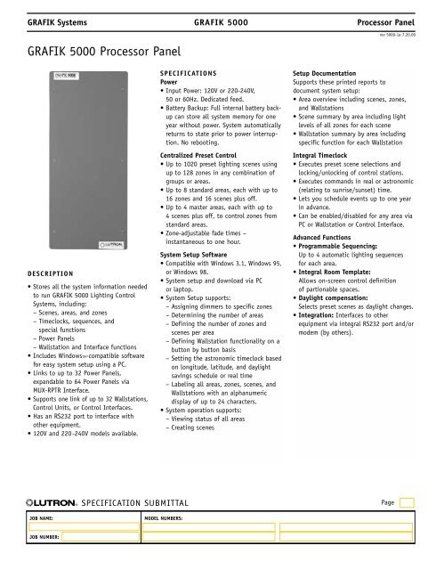
<strong>GRAFIK</strong> Systems<strong>GRAFIK</strong> <strong>5000</strong> <strong>Processor</strong> <strong>Panel</strong><strong>GRAFIK</strong> <strong>5000</strong><strong>Processor</strong> <strong>Panel</strong>rev <strong>5000</strong>-1a 7.20.00DESCRIPTION• Stores all the system information neededto run <strong>GRAFIK</strong> <strong>5000</strong> Lighting ControlSystems, including:– Scenes, areas, and zones– Timeclocks, sequences, and– special functions– Power <strong>Panel</strong>s– Wallstation and Interface functions• Includes WindowsTM-compatible softwarefor easy system setup using a PC.• Links to up to 32 Power <strong>Panel</strong>s,expandable to 64 Power <strong>Panel</strong>s viaMUX-RPTR Interface.• Supports one link of up to 32 Wallstations,Control Units, or Control Interfaces.• Has an RS232 port to interface withother equipment.• 120V and 220-240V models available.SPECIFICATIONSPower• Input Power: 120V or 220-240V,50 or 60Hz. Dedicated feed.• Battery Backup: Full internal battery backupcan store all system memory for oneyear without power. System automaticallyreturns to state prior to power interruption.No rebooting.Centralized Preset Control• Up to 1020 preset lighting scenes usingup to 128 zones in any combination ofgroups or areas.• Up to 8 standard areas, each with up to16 zones and 16 scenes plus off.• Up to 4 master areas, each with up to4 scenes plus off, to control zones fromstandard areas.• Zone-adjustable fade times –instantaneous to one hour.System Setup Software• Compatible with Windows 3.1, Windows 95,or Windows 98.• System setup and download via PCor laptop.• System Setup supports:– Assigning dimmers to specific zones– Determining the number of areas– Defining the number of zones and– scenes per area– Defining Wallstation functionality on a– button by button basis– Setting the astronomic timeclock based– on longitude, latitude, and daylight– savings schedule or real time– Labeling all areas, zones, scenes, and– Wallstations with an alphanumeric– display of up to 24 characters.• System operation supports:– Viewing status of all areas– Creating scenesSetup DocumentationSupports these printed reports todocument system setup:• Area overview including scenes, zones,and Wallstations• Scene summary by area including lightlevels of all zones for each scene• Wallstation summary by area includingspecific function for each WallstationIntegral Timeclock• Executes preset scene selections andlocking/unlocking of control stations.• Executes commands in real or astronomic(relating to sunrise/sunset) time.• Lets you schedule events up to one yearin advance.• Can be enabled/disabled for any area viaPC or Wallstation or Control Interface.Advanced Functions• Programmable Sequencing:Up to 4 automatic lighting sequencesfor each area.• Integral Room Template:Allows on-screen control definitionof partionable spaces.• Daylight compensation:Selects preset scenes as daylight changes.• Integration: Interfaces to otherequipment via integral RS232 port and/ormodem (by others).® SPECIFICATION SUBMITTALPageJOB NAME:MODEL NUMBERS:JOB NUMBER:
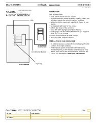
<strong>GRAFIK</strong> Systems<strong>GRAFIK</strong> <strong>5000</strong><strong>Processor</strong> <strong>Panel</strong>rev <strong>5000</strong>-2a 7.20.00System Communications and CapacitiesLow-voltage type Class 2 (PELV) wiring connects <strong>Processor</strong> to:• One personal computer• Up to 32 Dimming or Switching Power <strong>Panel</strong>s, expandable to 64Power <strong>Panel</strong>s via MUX-RPTR Interface.• Up to 32 total Wallstations, Control Units, and Control Interfaces.Physical Design• Enclosure: NEMA-Type 1, IP-20 protection; #18 U.S. Gauge Steel.Indoors only.• Weight: 45 pounds (20kg).• Mounting: Recess or surface mount.Environment32-104°F (0-40°C). Relative humidity less than 90% non-condensing.MODELSMAXIMUMINPUT POWER ADDRESSES 1 MODEL120VAC, 15A 32 GR5MXINP220-240VAC, 10A 32 GR5MXINP-220/2401 Wallstations, Control Units, and/or Control InterfacesDIMENSIONSFront View Right Side View Top View14.38"(36.5cm)1.5"(3.8cm)DedicatedFeed Wiring6.475"(16.2cm)2"(50.8mm)3.875"(9.5cm)Bottom View1/2" Conduit Knockouts34.75"(88.3cm)MountingHolesScrews(4) forhangingsubplateMountingHolesMountingHolesfor FlushMountingPower<strong>Panel</strong> LinkUser Interface LinkWallstation LinksRS232 InputEnters Here7"(17.5cm)2.875"(7.2cm)2.875"(7.2cm)® SPECIFICATION SUBMITTALPageJOB NAME:MODEL NUMBERS:JOB NUMBER:
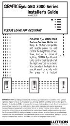
<strong>GRAFIK</strong> Systems<strong>GRAFIK</strong> <strong>5000</strong><strong>Processor</strong> <strong>Panel</strong>rev <strong>5000</strong>-3a 7.20.00MOUNTINGRecess or surface mount indoors.• Make sure relative humidity is less than 90% non-condensing.• Reinforce wall structure if necessary. <strong>Processor</strong> weighs45 pounds (20kg).Recess MountCeilingSurface MountCeilingDedicatedfeedDedicatedfeedClass 2PELVwiringWall showncut awayStuds mounted 16"(407mm) on centerClass 2PELVwiringSpace this surface 1/8"(32mm) off of mountingsurface to allow subplateto protrudeFront ViewSide ViewFront ViewSide ViewSurface mount as shown!• Back surface must be 1/8" (32mm) away fromthe wall. Subplate mounting screws must protrude1/8" (32mm) behind panel.• Use only the four holes indicated when surfacemounting. You’ll need the other holes for mountingthe subplate.Water Damages <strong>Processor</strong>s!Install <strong>Processor</strong>s in a locationwhere they won’t get wet® SPECIFICATION SUBMITTALPageJOB NAME:MODEL NUMBERS:JOB NUMBER:
<strong>GRAFIK</strong> Systems<strong>GRAFIK</strong> <strong>5000</strong><strong>Processor</strong> <strong>Panel</strong>rev <strong>5000</strong>-4a 7.20.00LINE VOLTAGE WIRING• Make sure line voltage feed wiring enters <strong>Processor</strong> from top right.• Run wiring so that line (mains) voltage is at least 6 feet (1.8m)from sound or electronic equipment and wiring.To dedicatedfeed circuitNHLOW-VOLTAGE CLASS 2 (PELV) WIRINGPull low-voltage Class 2 (PELV) wiring 1 for system communications.• Must be daisy-chained!• Must run separately from line (mains) voltage.• Use the MUX-RPTR Interface and GRX-CBL-46L cable for linksgreater than 2000 feet (600m).• Wire as shown for links 2000 feet (600m) and less.Ground/EarthNeutralHot/LiveDimming <strong>Panel</strong><strong>Processor</strong>Control UnitControl InterfaceWallstations<strong>Panel</strong> Link Power<strong>Panel</strong>-to-<strong>Panel</strong> wiring 1Include one extra #18AWG(1.0mm 2 ). Used as a “sense line”for emergency (essential) lighting.User Interface Link to PCEach Class 2 (PELV) wiring link has:• Two #12 AWG (2.5mm 2 ) conductors for control wiring.• One shielded, twisted pair #18 AWG (1.0mm 2 ) for data link.1If you use <strong>Lutron</strong> cable, you can use smaller-gauge wires.• If a Class 2 (PELV) wiring link is less than 500 feet (150m), you can use GRX-CBL-346S:- Two #18AWG (1.0mm 2 ) for power.- One twisted, shielded pair #22AWG (.625mm 2 ) for data link.- No “sense line” included - add your own #18AWG (1.0mm 2 ).• If a Class 2 (PELV) wiring link is 500 to 2000 feet (150 to 600m), you can use GRX-CBL-46L:- Two #12AWG (2.5mm 2 ) for power.- One twisted, shielded pair #22AWG (.625mm 2 ) for data link.- One #18AWG (1.0mm 2 ) for sense line between <strong>Panel</strong>s.• <strong>Lutron</strong> has also approved smaller-gauge cable from Belden, Liberty, Alpha, and Signature.Ask for <strong>Lutron</strong> <strong>GRAFIK</strong> Eye ® Cable.® SPECIFICATION SUBMITTALPageJOB NAME:MODEL NUMBERS:JOB NUMBER:
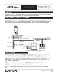
1 2 3 4 5 1 2 3 4 5 1 2 3 4 5 1 2 3 4 5 1 2 3 4 5DIMMER PANELLINKUSER INTERFACECONTROLLINK #_____CONTROLLINK #_____CONTROLLINK #_____NUNSWITCHEDSYSTEM POWERPOWERH1 2 3 4 5 6<strong>GRAFIK</strong> Systems<strong>GRAFIK</strong> <strong>5000</strong><strong>Processor</strong> <strong>Panel</strong>rev <strong>5000</strong>-5a 7.20.00CLASS 2 (PELV) TERMINAL CONNECTIONSUse Link Terminators at the beginning and endof all low-voltage Class 2 (PELV) wiring links:• Wallstation Links• Power <strong>Panel</strong> Links• User Interface to PC.<strong>Processor</strong><strong>Panel</strong>WALLSTATIONLINK POWERSUPPLYMAINBOARDPOWERSUPPLYWallstationWallstationLast Wallstation/Control Unit on Link1234561 2 3 4 5 61 Common2 +V3 MUX4 MUX5 Shield432112341 2 3 4Ceiling Receiver3 4 3 4Control Wiring(2) #12 AWG (2.5mm 2 )1: Common2: +24VFWData Link(1) Shielded, twistedpair #18 AWG (1.0mm 2 )3: MUX4: MUXLinkTerminatorLinkTerminator® SPECIFICATION SUBMITTALPageJOB NAME:MODEL NUMBERS:JOB NUMBER: