
You also want an ePaper? Increase the reach of your titles
YUMPU automatically turns print PDFs into web optimized ePapers that Google loves.
ii • <strong>AMMCO</strong> <strong>7000</strong> <strong>Brake</strong> <strong>Lathes</strong><strong>Brake</strong> <strong>Lathes</strong>
<strong>Brake</strong> <strong>Lathes</strong>Lathe OperationOperating SpecificationsCross Feed SpeedSpindle Speeds:Pulley: Inner GrooveMiddle GrooveOuter GrooveInfinitely Variable0.002 in./rev. to 0.006 in./rev.(0.051 to 0.152 mm)100 RPM150 RPM200 RPMSpindle Diameter2-718" (73.02 mm)Capacities:Maximum <strong>Brake</strong> Rotor Diameter (3/8" Thick Rotor) 19-3/4"Maximum <strong>Brake</strong> Rotor Diameter (1-3/4" Thick Rotor) 20-1/2"Maximum Rotor Thickness1-3/4" (44.45 mm)Maximum Arbor Load1 Inch Standard Arbor 100 lbs. (45.4 kg.)1.875 Inch Optional Arbor 200 lbs. (90.7 kg.)Shipping Weight (Lathe Only)Electrical RequirementsFloor Space Requirements(When Mounted On Optional Bench)315 lbs. (143 kg.)115 VAC, 60 Hz, I Ph, 14 amp - standard220 VAC, 60 Hz, I Ph, 7 amp - optional(Unless Otherwise Specified)48 in. wide x 34-3/4 in. deep(1219.20 mm x 882.65 mm)2 • <strong>AMMCO</strong> <strong>7000</strong> <strong>Brake</strong> <strong>Lathes</strong>
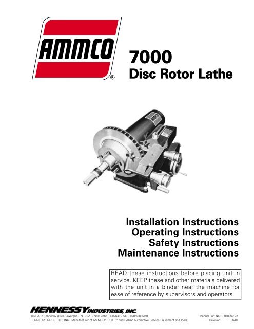
Lathe Components<strong>Brake</strong> <strong>Lathes</strong><strong>AMMCO</strong> <strong>7000</strong> <strong>Brake</strong> <strong>Lathes</strong> • 3
Figure B1Figure B2Figure B3<strong>Brake</strong> <strong>Lathes</strong>Arbor InstallationThe 1" arbor shipped with the lathe has been carefully matchedto the lathe during final assembly and testing. Witness markshave been etched onto the arbor and spindle for repeatable, precisealignment.The witness marks should be carefully aligned when installingthe arbor, Fig. B 1. A true running arbor is essential to professionalquality rotor reconditioning.The drawbar, which can be tightened or loosened at the rear ofthe spindle, pulls the hardened and ground tapers of the arborinto the matching seats.AdaptersCAUTIONAlthough the adapters, arbor, and spindle are madeof top grade steel and are turned, hardened, and precisionground to close tolerances, great care shouldbe taken in their use, handling, and storage. Eventhe smallest nick, scratch or loose chip on the matingmachined surfaces, Fig. B 2, can cause incorrectrotor mounting alignment.This will cause inaccuratemachining.Note: A light film of oil should be put on all adapters to protectthe machined surfaces from rust. Always inspect the surface,the face and the seating tapers of each part. Wipe each partclean before and after using it. Carefully correct any flaw with afine stone. If damage cannot be corrected, replace the part.Basic OperationTo completely understand rotor turning you must have aknowledge of the lathe itself.The spindle is a motor driven shaft that turns the arbor onwhich the brake rotor is mounted. By turning the rotor and holdinga cutting tool to the rotor, metal can be removed.By operating the cross feed lever the cutting tool is automaticallydrawn across the rotor brake face as the cross feed movesaway from the tool while the rotor turns. Cross feed may alsobe done manually using the cross feed handwheel.CAUTIONDo not try to move any feed levers or dials withoutthe drive motor running. Damage may occur to thegear trains.AdjustmentsSpindle Speed - Release the belt tension by moving the V-beltadjusting lever clockwise, Fig. B 3. Move the belt to the pulleygroove that will give the correct spindle speed for the cut to betaken, Fig. B 4.Figure B44 • <strong>AMMCO</strong> <strong>7000</strong> <strong>Brake</strong> <strong>Lathes</strong>
<strong>Brake</strong> <strong>Lathes</strong>Cross Feed - The cross feed draws the twin tool bits across theface of a brake rotor when the cross feed drive is engaged. Thecross also be operated manually using the cross feed handwheel.Feed Speed - Feed speed refers to the number of thousandthsof an inch the cutting tools move across the face of the rotor perrevolution of the spindle. The cross feed speed control adjuststhe feed rate from .002" (.05 mm) to .004" (.10 mm) to .006" (.15mm) per spindle revolution.V-Belt Tension - When properly adjusted, the V-Belt should have1/4" - 1/2" of slack. To adjust the tension, loosen the tensionadjusting nut so the weight of the motor pulls the V-Belt snugand rotate red knob to its furthest counterclockwise position.Push the belt in 1/4" - 1/2" on one side and tighten the nut, Fig.B 5.Cross Feed Leg Tension -- Be sure the brass plug and springare under the allen screw. (if the cross feed has been pulled outbeyond the end of the guide bar, the plug and spring may havebeen lost.) Replace the plug and spring, Fig. B 6, then snug theallen screw all the way down then back it off 1/8" of a turn.Tool-Bit Holder Adjustment (Preliminary Cleaning) - Refer toparts identification manual for nomenclature.Before adjusting the tool-bit holders on a used twin cutter, thefollowing steps should be performed.1. Be sure the tool-bit holder bores in the twin cutter body areclean along with the tool-bit holders and tool-bit assemblies.2. Replace the brass plugs if the original plugs are “mushroomed”or worn.3. Clean the threads of the lock knob holes by running a tapthrough them.(Adjusting Tool-Bit) - Refer to parts identification manual fornomenclature.1. Loosen and back off the hex nut locking the locating screwin position.2. Loosen and back off the lock knob.3. Firmly tighten the locating screw to align the tool-bit holderby its locating groove.4. Simultaneously loosen the locating screw and tighten thetool-bit holder lock knob until the locating screw is loose and thelock knob is tight.5. Screw the locating screw in until it is snug, then back it off1/8 to 1/4 of a turn.6. Hold the locating screw in this position and tighten the hexnut to lock the screw in place.7. Turn the outer knurl of the twin cutter control left and rightto check for a smooth, free movement. Repeat the procedurefor the other tool-bit holder.Figure B5Figure B6<strong>AMMCO</strong> <strong>7000</strong> <strong>Brake</strong> <strong>Lathes</strong> • 5
Figure B7Figure B8<strong>Brake</strong> <strong>Lathes</strong>Reconditioning Disc <strong>Brake</strong> RotorsEach brake disc should be carefully inspected for SCORING,RUST RIDGES (at the inner and outer circumference of therotor), and HARD SPOTS. Any excessive wear or deformityshould be noted and, if not within acceptable limits, the rotorshould be replaced. Use a micrometer to check the thickness ofthe rotor at no less than three points around the circumferenceabout 1" (25.4 mm) in from the outer diameter, Fig. B 7. If therotor thickness varies between readings, it should be machined;however, if the thickness is less than the minimum establishedby the car manufacturer (or if it will be less after reconditioning),the rotor should be replaced.Note: Most often the discard thickness dimension is cast intothe rotor, not the minimum machine to thickness.Mount the twin cutter on the cross feed with the stud boltextending through the cast slot. In some applications the studbolt may have to be positioned in one of the alternate studmounting holes, Fig. B 8. To prevent contamination of the gearbox position set screw in unused hole. To secure the twin cutteruse the nut and washer assembly and tighten firmly.Rotor MountingFig. B20, TYPICAL ROTOR MOUNTING CONFIGURATIONS isa model example of many of the mounting configurations necessaryto meet the requirements of brake rotor machining.Inspect the rotor hub for loose or damaged bearing races andreplace parts as necessary. Hubbed rotors are mounted on thetaper adapters that fit into the bearing races. Hubless rotors usea cone in the center hole and a hubless adapter on each side ofthe rotor. Spacers are used to fill out the arbor shaft so that thearbor nut can be tightened. The adapters, cones, and spacerssupplied with your lathe will allow you to recondition the majorityof rotors on today’s vehicles. Optional adapters, cones, andspacers are available to meet special needs.Note: Adapters may also be used as spacers to fill out thearbor if care is taken to prevent damage to their machined surfaces.The patented self-aligning spacer prevents diagonal thruston the adapters. The self-aligning spacer should always be usedadjacent to the arbor nut.6 • <strong>AMMCO</strong> <strong>7000</strong> <strong>Brake</strong> <strong>Lathes</strong>
<strong>Brake</strong> <strong>Lathes</strong>Reconditioning Disc <strong>Brake</strong> Rotors—Set-Up1. After the brake rotor is mounted on the arbor, install thesilencer band. This is easily done by stretching the band to itsfull length and then wrapping it around the rotor and hookingthe end metal loop over a lead weight, Fig. B 9.2. Center the twin cutter to the rotor. Loosen the stud nut,Fig. B 10, and adjust the twin cutter so that the rotor is centeredbetween the tool bits. The slot of the twin cutter should beapproximately parallel to the lathe spindle. Tighten the stud nutfirmly.3. Install the safety shield. Review the CAUTIONS / DAN-GERS and GENERAL SAFETY INSTRUCTIONS. The safetyshield is easily screwed onto the twin cutter in the threadedmounting hole provided, Fig. B 11. Also always wear safetyglasses or a face shield. Cutting or grinding on an exposed surfacesuch as a rotor will produce flying chips.Figure B9Figure B11Figure B10<strong>AMMCO</strong> <strong>7000</strong> <strong>Brake</strong> <strong>Lathes</strong> • 7
Figure B12<strong>Brake</strong> <strong>Lathes</strong>4. Adjust the drive belt to match the rotor size. Use the outerpulley groove for all passenger car and light truck rotors, Fig. B12. Choose one of the inner grooves when machining mediumduty truck rotors.5. Make sure that the tool bits clear the rotor faces and thesilencer band. Give the rotor a full turn by hand and start thelathe.6. Turn each tool bit control (the outer knurled knobs) clockwiseuntil the tool bits just contact the rotor faces. When thetool bits have made contact, rotate each of the inner depth-ofcutcollars to zero and back the tool bits away from the rotor.From this point on all tool adjustments will be made with thetool bit controls, Fig. B 13. The inner depth-of-cut collars will bethe reference and should not be moved.7. Turn the cross feed handwheel until the tool bits are at midpointof the rotor face. Turn the left hand tool bit control until thetool bit contacts the rotor surface and makes a scratch cut nodeeper than .001", Fig. B 14.Figure B13Figure B148 • <strong>AMMCO</strong> <strong>7000</strong> <strong>Brake</strong> <strong>Lathes</strong>
<strong>Brake</strong> <strong>Lathes</strong>The scratch will usually appear as an incomplete circle. This iscaused by runout or wobble due to rotor condition or by the waythe rotor is mounted on the arbor.To check that the rotor is correctly mounted, loosen the arbornut and turn the rotor 180° by hand, (make sure the insideadapter does not rotate along with the rotor), Fig. B 15.Retighten the arbor nut. Turn the cross feed handwheel backabout a half turn, start the lathe and move the tool bit in to makea second scratch cut. Stop the lathe.If the scratch cuts are side by side, Fig. B 16, next page, therunout or wobble is caused by the rotor condition. A dial indicatormay be used to compare rotor runout with manufacturer’sspecifications.If the scratch cuts are opposite one another (180°), Fig. B 17,the rotor may not be properly mounted on the arbor. Removethe rotor from the arbor. Examine each adapter and the arbor fornicks, burrs, chips, dirt, and rust. Also inspect the rotor hub forloose or damaged bearing cups. Clean, repair, remount, orreplace as necessary.Figure B15Figure B16Figure B17<strong>AMMCO</strong> <strong>7000</strong> <strong>Brake</strong> <strong>Lathes</strong> • 9
Figure B18<strong>Brake</strong> <strong>Lathes</strong>Machining8. Recheck the setting of the depth-of-cut collars which wereon zero. Move the tool bits inward until they just contact thefaces of the rotor. Reset the collars if necessary.9. Turn the cross feed handwheel clockwise until the tool bitsare near the rotor hub, Fig. B 18. Start the lathe. Turn both toolbit controls to the desired depth-of-cut and lock them in position.Note: Either rough or finish cuts may be taken to resurface arotor. Generally, finish cuts should be .004" (.10 mm) to .006"(.15 mm). Very shallow cuts [less than .004" (.10 mm)] tend toreduce tool bit life because heat won’t transfer to the rotor efficiently.Move the cross feed speed control knob to the fast position forroughing cuts.10. Now engage the automatic cross feed (by moving theknob), Fig. 19. When the cross feed has moved the cutting toolsall the way across the face of the rotor, the feed will shut offautomatically.Figure B1910 • <strong>AMMCO</strong> <strong>7000</strong> <strong>Brake</strong> <strong>Lathes</strong>
Figure C1<strong>Brake</strong> <strong>Lathes</strong>Maintenance and ServiceNote: Refer to LATHE COMPONENTS.OilingThe lathe is shipped from the factory with the correct amountand type of oil. Refill as necessary with EP-80-90 gear oil andcheck the oil level often., Fig. C 1.Every 500 hours drain the oil and refill to the dipstick level withclean EP-80-90 gear oil. To drain the oil, remove the socket headdrain plug located on the front of the lathe to the right of thecross feed assembly, Fig. C 2.Cross Feed - Once a month pump automotive chassis greaseinto the cross feed grease fitting until it begins to come out ofthe relief slot at the base of the fitting. CAUTION: Use a HANDGREASE GUN ONLY, a high pressure gun can burst the lathecasting, Fig. C 3.CleaningKeep the lathe as clean as possible for trouble free operationas well as safety and longer lathe life. Use a brush to sweepmetal chips and dust off the lathe. DO NOT USE COMPRESSEDAIR TO BLOW THE LATHE CLEAN. Chips and dust could bedriven between machined parts and into bearings causingundue wear.Figure C2Figure C312 • <strong>AMMCO</strong> <strong>7000</strong> <strong>Brake</strong> <strong>Lathes</strong>
Care of Arbors and Adapters<strong>Brake</strong> <strong>Lathes</strong>CAUTIONAlthough the adapters, arbors, and the spindle aremade of top grade steel and are turned, hardened,and precision ground to close tolerances, great careshould be taken in their use, handling, and storage.Even the smallest nick, scratch, or loose chip cancause incorrect rotor alignment, resulting in inaccuratemachining.Remove all adapters from the arbor after machining a rotor andwipe them clean - especially the inboard adapter. When a finishedrotor is removed from the arbor, the inboard adapter maymove slightly away from the face of the arbor and allow metalchips to fall into the opening causing a poor mounting for thenext rotor.Regularly inspect the faces and seating tapers of the adaptersfor nicks and scratches, correct any flaw with a fine stone. If thedamage cannot be corrected, replace the adapter. Handle theadapters and arbors with care and store them on individualhooks. DO NOT throw them into a box. The adapters aredesigned for mounting rotors only, DO NOT misuse theadapters.<strong>AMMCO</strong> <strong>7000</strong> <strong>Brake</strong> <strong>Lathes</strong> • 13
910369 02 06/01 © Copyright 1989 Hennessy Industries and <strong>AMMCO</strong> All Rights Reserved Printed in USA