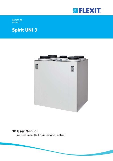
User Manual - Flexit
User Manual - Flexit
User Manual - Flexit
Create successful ePaper yourself
Turn your PDF publications into a flip-book with our unique Google optimized e-Paper software.
UNI 3 <strong>User</strong> <strong>Manual</strong>3 Cleaning and MaintenanceCAUTION! Before opening the door: switch off! the heat, let the fans continue for three minutesto remove hot air, disconnect power from theunit and wait 2 minutes before opening the doors.!CAUTION! For safety reasons, always mountthe door screw when you’re finishedmaintaining the ventilation unit!3.1 FansThe fans must be cleaned a minimum of once a year. Cleanthe fan blades with detergent (for example methylated spirit)on a cloth and compressed air if possible. NB! Do not usewater.To take out the fans:1. Loosen the screw on the fan door (see Fig. 12).2. Pull out the electric quick-release contact for the motor(see Fig. 13).3. The fan can then be carefully pulled out of the unit (seeFig. 14).4. Loosen the screws and remove the fan cover to accessthe fan blades.Fig. 12 Fig. 13 Fig. 14127
UNI 3 <strong>User</strong> <strong>Manual</strong>3.2 FilterThe filters have a limited lifetime, and to preserve ahealthy indoor air quality it is important to change themwhen they are dirty.Fig. 15How often the filters need to be changed depends on thedegree of contamination in the air where they are installed.In general, the filters need to be changed a minimum of oncea year, preferably in the autumn (after the pollen season). Inareas with a lot of dust and contamination, the filters shouldbe changed in the spring and autumn.Dirty filters can, among other things, lead to:• Reduced performance of the unit• The unit becoming dirty• Humidity damage in the bathroom• Reduced indoor air qualityA filter subscription is recommended to ensure full benefitfrom the system. The article number for a replacement filterset is 110716.To take out the filters:1. Grip the handle and pull the filter cassette out (see Fig.15).2. Push the filter out of the cassette (see Fig.16).3. Insert a new filter.NB! Ensure that the filter is not damaged duringinstallation. Use the filter’s outer edge when youpush it in. A damaged filter reduces the unit’seffect and the air’s purity.Fig. 16When changing the filter, check that the whole unit is workingnormally. Use the following checklist:• Check that the rotor is rotating (see Fig. 17).• The unit has filters both for outdoor air and extract air.• Check that the fans are clean.Fig. 17NB! When inserting the filter cartridge into itsslot, push it properly to prevent air leakage.8
UNI 3 <strong>User</strong> <strong>Manual</strong>3.3 Replacing the brush stripsThe brush strips become worn over time. If they do notsit tightly against the rotary wheel-type heat exchanger,it can be necessary to replace them (art.no.110894).Alternatively, they can be moved closer to the rotor, wherethe aluminium profile they are mounted in has two grooves.Fig. 18Do the following:1. Pull the rotor a little way out (see Fig. 18).2. Unplug the quick-release contact fastened to the rotor(see Fig. 19).3. Pull the rotor out completely.4. Remove the screw in the centre of the aluminium profileand pull the profile out (see Fig.20).5. Pull the brush strips out of the groove. Move them upfrom level 1 to level 2 (see Fig. 21), or replace them withnew ones if they are completely worn out.3.4 RotorAs the unit has high impermeability, filters installed, it is notusually necessary to clean the rotor. If, for various reasons,it should still be necessary, dust can be removed with a softbrush. Further cleaning is possible if you remove the rotor,spray it with fat-soluble detergent and then blow it cleanfrom the opposite side. Distance approximately 60 mm andmax. pressure 8 bar. Ensure that the motor is not exposed towater during cleaning. Ensure that all seals around the rotorare intact and tight. Ensure that there is no damage to therotor belt, and that the rotor rotates freely.Fig. 193.5 External CleaningMany kitchen surface cleaners contain chemicals thatmay damage the product’s plastic components. Thereforeuse a soft cloth moistened with warm water and a neutraldetergent to clean the outside of the product.NB! Do not use abrasive cleaners or scouringpowder, as such products can damage thesurfaces. Do not use cleaners containing citricacids or ammonia. Products that give stainless steelan anti-fingerprint coating must not be used either.Fig. 20Fig. 21level 1level 29
CI60 <strong>User</strong> <strong>Manual</strong>4 CI60 control unit overview834915102611712No. Description1 Switch for increased ventilation2 Switch for decreased ventilation3 Indication of MAX speed4 Indication of NORMAL speed5 Indication of MIN speed6 Indication of ALARM7 Indication of FILTER REPLACEMENTNo. Description8 Potentiometer for adjusting extract airat NORMAL speed9 Potentiometer for adjusting supply air atNORMAL speed10 Switch for additional heating OFF/ON11 Potentiometer for adjusting supply airtemperature12 Switch to reset the alarm*The figures are used as references in subsequent descriptions10
CI60 <strong>User</strong> <strong>Manual</strong>5 CI60 in use5.1 GeneralThe control unit consists of a touch panel with pushbuttons,LEDs for indication and adjustment potentiometers andswitches for adjusting the ventilation unit. The control unitcommunicates with the ventilation unit via a low-voltagecable.5.2 Increasing/reducing air supplyUse switches 1 and 2 to increase and reduce the fan speedand thus the air flow. Different speeds depending on theoperating situation.MINNORMALMAXDo not use during first year of operation, orwhen the building is in use.Used under normal conditions. In thissetting, the air supply must be adjustedaccording to current regulations.Used if there is a need for increased airsupply on account of increased occupancyor a higher humidity level, for exampleduring showering or when clothes are beingdried. This setting is usually used for limitedperiods of time.The different speeds are indicated with LEDs 3, 4 and 5.5.3 Adjusting the air supplyAt NORMAL speed level, the air flow must be adjustedaccording to project data. Potentiometer 9 is used for thesupply air level and potentiometer 8 for the extract air level.The adjustment range is 20-100% of the maximum levelaccording to the scale of the potentiometer.Factory settings:MIN 50% (fixed)NORMAL 75% (variable)MAX 100% (fixed)9810 115.4 Temperature adjustmentThe temperature required in the supply air can be set withpotentiometer 11. The adjustment range is 10 - 30 °C. Usingthe factory settings is recommended.If necessary, the ventilation unit’s additional heating can alsobe switched OFF/ON with switch 10.ITEM 10ON5.5 Filter replacementEvery six months, LED 6 lights up to remind you that it is timeto replace the air filters in the unit. See section 3 for moreinformation on filter replacement.After the activity has been carried out, theindicator must be reset. See more under theReset section.5.6 AlarmIf anything unforeseen occurs with the!ventilation unit, indicator 6 lights up.The signal given by the indicator depends on the reason forthe indication.A permanent light indicates:• Fault return water detector (B5)• Heat recovery fault (B)OFFA permanent light with indicator 5 (MIN speed) flashingindicates:• Fault supply air detector (B1)• Fault extract air detector (B3)• Fault outdoor air detector (B4)A flashing light indicates:• Overheating thermostat fault (applies only to electricheating)• Fault in external fire/smoke detector (accessory)• Heat recovery fault (A)• Additional heating fault (applies only if the unit has awater battery)5.7 ResetAfter the filter has been replaced or the cause of the alarmrepaired, the alarm must be reset. This is done by pressingswitch 12.If the indicator goes out, the action has been carried outcorrectly. If the indicator remains on, the fault has not beenrepaired correctly.11
CI600 <strong>User</strong> <strong>Manual</strong>6 CI600 control unit overview61728394 5No. Description1 UP/INCREASE switch2 BACK/CANCEL/NO switch3 DOWN/DECREASE switch4 OK/YES switch5 HELP switch6 Display7 Indication of OPERATION/OK - Green light8 Indication of FILTER REPLACEMENT - Yellow light9 Indication of ALARM - Red light*The figures are used as references in subsequent descriptions12
CI600 <strong>User</strong> <strong>Manual</strong>7 CI600 in use7.1 GeneralThe control unit consists of a colour display, a touch paneland indicators (LEDs). The unit communicates with theventilation unit via a low-voltage cable.7.2 Idle modeIf the touch panel is not used, the control unit will, after acertain period of time, enter idle mode, in which operatinginformation will be displayed.A B CIf you select a function that has numerical values, thecurrent value is displayed with a light blue cursor. The valueis changed with buttons 1 and 3 and is then confirmed bypressing button 4.TIME AND DATETIMEDAY MONTH YEAR13 : 45 04.07.0907 09OK?13.08.200916:43 18°C 22°C- NORMALD E FA. Time and dateB. Outdoor air temperatureC. Room temperatureD. Current speedE. Additional heating activated/deactivatedF. Daily/weekly timer active7.3 Menu navigationButtons 1 and 3 are used to navigate through the menu lines.The cursor is illustrated by the line being light blue. If it ispossible to make a selection on the current menu line, thisis displayed with OK? to the right of the line. A selection isconfirmed by pressing button 4.If a menu line contains submenus, this is illustrated with a ‘>’sign at the end of the line.If several values can be changed, the cursor jumps tothe right when a selection is confirmed with button 4. Theprocedure is repeated until all values have been changed tothe desired values.If you want to cancel a function or return to the previousmenu screen, use button 2.Button 5 activates a help text that briefly describes thecurrent menu screen.7.4 Start menuWhen the system is started, a start menu is opened.START MENULANGUAGETIME AND DATEMAIN MENUOK?>>SETTINGSTEMPERATURETIMERDAY/WEEK SETTINGSTIME AND DATELANGUAGEFILTERALARMADVANCED USEROPERATING INFORMATION>>OK?>>>>>>The basic language and date settings are set in this menu.When this activity has been carried out, you choose to go tothe main menu.7.5 Operating statusIn normal operation without problems, the green LED 7lights up to confirm that everything is working normally. Howany problems affect the system is described in subsequentsections.13
CI600 <strong>User</strong> <strong>Manual</strong>8 CI600 main menu8.1 Fan speedsThe main menu contains various choices. Most concernfan speeds. The speed selected is indicated with large fansymbols and bold font.MAIN MENUMINNORMALMAXMAX TIMEROK?8.2 Max. timerThis menu item activates a function that increases the speedto MAX for a limited period of time before subsequentlyreturning to the speed selected previously. The period of timecan be adjusted under the SETTINGS menu item.MAIN MENUMINNORMALMAXMAX TIMEROK?SETTINGS >To change the speed, move the cursor with buttons 1 and 3.MAIN MENUMINNORMALMAXMAX TIMEROK?SETTINGS >When the function is active, the time is counted down on thedisplay. If you select TIMER OFF, the function will be cancelledand the speed will return to the previous selection.8.3 SettingsUnder the SETTINGS menu item, you can adapt the systemas you want.SETTINGSSETTINGS >Then confirm your selection with button 4 and the speedselected is highlighted with large fan symbols and bold font.MAIN MENUMINNORMALMAXMAX TIMEROK?SETTINGS >TEMPERATURETIMERDAY/WEEK SETTINGSTIME AND DATELANGUAGEFILTERALARMADVANCED USER>>OK?>>>>>8.4 TemperatureHere you set the temperature for the air that enters thebuilding.TEMPERATURE18 OK?°CHEATING ELEMENT ON/OFF>14
CI600 <strong>User</strong> <strong>Manual</strong>We recommend adjusting the temperature to max 18° sothat the air is mixed optimally with the air already in thebuilding.8.6 Daily/weekly timerThe programming of the timer begins by selecting the day.In the HEATING ELEMENT OFF/ON menu item, the additionalheating in the ventilation unit can be switched off. In suchcase, only the rotating heat exchanger is used as a source ofheat.NB! This is not possible if the unit is installed with a waterbattery.If the heating element is switched off, thissymbol is displayed when the display enters idlemode.DAY / WEEK SETTINGSMONDAYTUESDAYWEDNESDAYTHURSDAYFRIDAYSATURDAYSUNDAYOK?HEATING ELEMENT ON/OFFHEATING ELEMENTON OK?A new menu screen appears under each day.TUESDAY1 08 : 00 -16: 00 MIN 16°2 16 : 00 -18: 00 NORMAL 18°3 18: 00 -19: 00 MAX 16°4 19 : 00 -24: 00 NORMAL 18°8.5 TimerHere you set the time you want for the MAX TIMER function.This is used when the function is activated from the mainmenu.TIMER60 min OK?Each day can be programmed with four different timeintervals. Adjust the start and stop times for each intervaland then adjust the desired speed and temperature. Toactivate the interval, select a green tick. A red cross meansthat the interval is not activated. If necessary, then selectanother interval and repeat the procedure.NB!The following rules apply to the programming:• An interval can never commence before aprevious one has been finished.• The stop time can never appear before the start time.After you have finished programming a day, repeat theprocedure for other days.When the timer is active, this symbol is displayedwhen the display enters idle mode.If there is no new time interval registered after the finishedperiod, the speed and temperature return to the setting thatwas previously active.15
CI600 <strong>User</strong> <strong>Manual</strong>8.7 Time and dateThe time and date can be adjusted in this dialog.INTERVAL CHANGE OF FILTERTIME AND DATETIMEDAY MONTH YEAR6 MND OK?13 : 45 04.07.0907 09OK?8.8 LanguageThe language selected can be changed in this dialog.LANGUAGENORSKENGLISHSVENSKADEUTCHNEDERLANDSSUOMIDANSKOK?When the filter alarm is triggered, the yellow indicator 8 lightsup and an information text appears. Follow the instructionsin the text. It is possible to go directly to this dialog fromthe message or via the menu tree. After the alarm has beenreset, the countdown to the next filter replacement begins.8.10 AlarmIf a problem occurs in the operation of the ventilation unit,an alarm will be triggered. The red indicator 9 lights upand an information text appears in the display. Follow theinstructions in the text. It is possible to go directly to thisdialog from the message or via the menu tree.ALARMRESET ALARMOK?8.9 FilterA reminder appears regularly in the display. In this dialog, thetime interval can be adjusted and the filter alarm reset.FILTERINTERVAL CHANGE OF FILTERRESET FILTER ALARM>OK?8.11 Operating informationThis general screen displays current temperature values,whether the daily/weekly timer is active and activity as0-100% for cooling, heat exchanger and additional heating.OPERATING INFORMATIONThe normal interval is 6 - 12 months, depending on theenvironment.SET TEMPERATUREDAY / WEEK SETTINGSSUPPLY AIREXTRACT AIROUTDOOR AIRRETURN WATERHEAT RECOVERY SYSTEMCOOLINGHEATING22°AKTIV22°21°0°35°100%0%100%16
CI600 <strong>User</strong> <strong>Manual</strong>9 CI600 advanced user menuNB! For more information on the ”Advanced<strong>User</strong>” menu, refer to the ”CI600 Reference <strong>Manual</strong>”on <strong>Flexit</strong>’s homepage.9.3 Temperature regulationIn this menu screen, you configure the temperatureregulation and cooling functions.9.1 PINTo access the menu item, you need to enter the PIN 1 0 0 0.PIN CODETEMPERATURE REGULATIONREGULATION TYPECOOLINGNEUTRAL ZONEEXT. TEMP. CONTROL>>OK?>1 0 0 0OK?9.2 Advanced userThis menu contains functions for monitoring, configurationand troubleshooting.ADVANCED USERTEMPERATURE REGULATIONFAN REGULATIONCONFIGURATIONOPERATING TIMEFACTORY SETTINGSSERVICE>OK?>>>>Regulation typeIf supply air regulation is selected, no further settings canbe set here. If extract air regulation is selected, the max. andmin. supply air temperatures can also be specified.REGULATION TYPEREGULATIONMAX SUPPLY AIR TEMPMIN SUPPLY AIR TEMPEXTR OK?35°15°CoolingNB! <strong>Flexit</strong> does not supply or project coolingmachines.In this dialog, the cooling function is activated and theparameters MIN OUTDOOR AIR TEMP for supply of coolingand MIN SPEED for supply of cooling are specified. If a DXcooling machine is used, the supply delay interval can bespecified.COOLINGCOOLINGMIN OUTDOOR TEMPMIN SPEEDRESTART DELAYCOOLNESS RECOVERYAV18°MIN180 sOK?>17
CI600 <strong>User</strong> <strong>Manual</strong>It is also possible to activate a function to recover coolingin the building using the rotating heat exchanger. Enterthe desired difference between the outdoor and indoor airtemperatures for when the function is activated.COOLNESS RECOVERYCOOLNESS RECOVERYDIFFOFF1°OK?Fan controlThe fans are selected and configured in this menu screen.FAN REGULATIONSUPPLY AIREXTRACT AIRTIMERAIR VOLUME COMP>>OK?>Neutral zonesTo achieve more even temperature regulation, the neutralzones can be set in this menu.NEUTRAL ZONECOOLNESS RECOVERYHEAT RECOVERY SYSTEM2°1°OK?Adjustment (supply air and extract air)This dialog is identical for the supply air and extract air fans.The fans are adjusted individually to the desired capacity forthe respective speed.SUPPLY AIRMIN SPEEDNORMAL SPEEDMAX SPEED50%75%100%OK?External temperature controlControl of the temperature settings from an overall systemmust be entered in this menu. In this case, the temperaturesettings in the control unit are overridden.EXT. TEMP. CONTROLFactory settings:MIN 5VNORMAL 7,5VMAX 10VEXT. TEMP. CONTROL OFF OK?18
CI600 <strong>User</strong> <strong>Manual</strong>TimerSettings are entered in this menu for the speed and time thatare to apply to the ‘MAX TIMER’ function in the main menu.9.4 ConfigurationThe general configuration is set in this menu screen.CONFIGURATIONTIMERSTANDARD SPEEDSTANDARD TIMEMAX30 mOK?SENSORSFIRE/SMOKECOMMUNICATIONSTART/STOP SEQUENCEREST MODE>>OK?>>Air flow rate compensationThis function can be activated via an input on the controlcard. The speeds required for each fan are selected here. Thefunction can be used with a kitchen fan or other device thatrequires additional supply air.SensorsThe temperature sensors can be calibrated in this menu tobe better coordinated with the real situation, and a pressuresensor is activated as a pressure guard instead of theintegrated time control.SENSORSAIR VOLUME COMPENSATIONSUPPLY AIREXTRACT AIRMAXMINOK?SUPPLY AIREXTRACT AIROUTDOOR AIRRETURN WATERFILTER GUARD>>OK?>>The menu screen is identical for all temperature sensors andthey can be adjusted within an interval of 5 °C.SUPPLY AIRCALIBRATION0OK?19
CI600 <strong>User</strong> <strong>Manual</strong>If the pressure guard is activated, an external sensor mustbe connected to the control card. The sensor replaces theintegrated filter time control.FILTER GUARDACTIVATIONOFFOK?CommunicationProceed to the ‘HOME/AWAY’ submenu.COMMUNICATIONHOME/AWAYOK?Fire/SmokeThis function requires an external sensor to be connected tothe control card.FIRE/SMOKEMODE1OK?The settings are entered for the AWAY selection. Speed andtemperature can be selected, plus how long after activationthe new setting should take effect.Standby modeIn this menu you can adjust the time it takes before thedisplay enters idle mode.REST MODETIME DELAY 2 min OK?Mode Supply air fan Extract air fan1 STOP STOP2 MAX MAX3 STOP MAX4 MAX STOP9.5 Operating timeThis menu screen displays the ventilation unit’s totaloperating time and how much time has passed since the lastfilter replacement.OPERATING TIMEOPERATING TIMEFILTER312 tim125 tim20
CI600 <strong>User</strong> <strong>Manual</strong>9.6 DefrostingThe integrated defrosting function is deactivated on deliveryof the ventilation unit.The function can be configured or activated in this menuscreen.Search path to menu screen:MAIN MENU/SETTINGS/ADVANCED USER/SERVICE/DEFROSTINGDE-ICINGPassword given only in consultation withthe <strong>Flexit</strong> service organisation.DE-ICINGSTART TEMPERATUREROTOR SPEEDFAN REDUCTIONOFF-15°25-25°OK?DefrostingActivates/deactivates the function.Start temperatureThe start temperature for the defrosting function is set here.The temperature in question is the outdoor temperature.Rotor speedWhen the start temperature has been reached, the speed ofthe drive motor of the rotating heat exchanger is reduced tothe specified RPM.Fan reductionAs an additional safety function, the speed of the supplyair fan can be reduced. This takes effect at the set outdoortemperature.Defrosting - ParametersParameter Default Area UnitDefrosting OFF OFF/ONStart temperature-15 (-5)-(-45) °CRotor speed 25 15-180 RPMFan reduction -25 (-5)-(-45) °C21
UNI 3 <strong>User</strong> <strong>Manual</strong>10 Maintenance TableComponent Action IntervalFiltersFilters must be replaced at least once a year. It is recommended to change them twice a year,before and after the pollen season. Check that the filter seal is completely tight.6-12monthsFans Fans must be cleaned at least once a year to maintain fan efficiency. 12 monthsRotorCheck that the surfaces are clean. Check that the sealing strips face in towards the rotarywheel-type heat exchanger. Check that the rotor belt is whole and not too slack.12 monthsKitchen hood* Wash the grease filter. Check that the damper is clean and closes fully. 2 weeksSeals Check that the seals in the unit are intact. 12 monthsValves To be cleaned at least once a year. 12 monthsAir intake Check that no leaves or other items have caught in the grille.In frost mist periods during winter the air intake can freeze up. If necessary it must be scrapedclean so that the air can pass through.12 monthsRoof cowl If the unit has a roof cowl, this must be checked for leaves and the like. Also check that the 12 monthsdrain slots are open.Ducts Check that the ducts are clean. 10 yearsBrush strips Check that the brush strips are whole and sit tightly against the rotor. If they are worn they 3 yearscan be moved to the next groove in the profile, so that they are closer to the rotor.Inside unit A combination of a very low outside temperature and damp extract air can lead to theformation of ice. Normally this will not be a problem - when normal operating conditionsreturn the ice crystals will be converted to damp and be removed from the unit via theexhaust air. In the case of extreme cold over longer periods the unit should be checked forice.*For units with extract air from the kitchen hood connected to the unit.11 TroubleshootingType of faultCold draughtsRemedial actionCheck which supply temperature has been selected. See operating panel.Check that the rotor is rotating.Check that heating comes on.Needs new extract filter.Fans not workingCheck that the power to the unit is connected.Check that the thermostat has not cut out.Reset by pressing the button. Must also be reset on the automatic panel.Low air volumeCheck the speed the unit is set to.Check that the filters are tight.Check the intake grille.22
UNI 3 <strong>User</strong> <strong>Manual</strong>12 CE Declaration of ConformityThis declaration confirms that the products meet therequirements in the following Council Directives andstandards:2004/108/EC Electromagnetic Compatibility (EMC)2006/95/EC Low-voltage Directive (LVD)2006/42/EC Machine Directive (Safety)Producer:NorwayFLEXIT AS, Televeien 15, 1870 Ørje,Type: UNI 3 R Ventilation unitComplies with the following standards:Safety standard: EN 60335-1:2002EMF standard: EN 50366:2003EMC standard: EN 55014-1.2000EN 61000-3-2:2000EN 61000-3-3:1995EN 55014-2:2:1997The product is CE-marked: 2010FLEXIT AS 26.08.2010Frank PetersenAdm. dir.The right to give notice of lack of conformity applies to this product inaccordance with the existing terms of sale, provided that the product iscorrectly used and maintained. Filters are consumables.The symbol on the product shows that this product must not betreated as household waste. It must be taken to a reception stationfor recycling of electrical and electronic equipment.By ensuring correct disposal of the equipment, you will contributeto preventing negative consequences for the environment andhealth that incorrect handling may entail. For further information onthe recycling of this product, please contact your local authority, your refusecollection company or the company from which you purchased it.Notice of lack of conformity as a result of incorrect or defective installation mustbe submitted to the installation company responsible. The right to give notice oflack of conformity may lapse if the system is used incorrectly or maintenance isgrossly neglected.23
<strong>Flexit</strong> AS, Televeien 15, N-1870 Ørje www.flexit.no


