FSO Proceedings of EuCAP2011 - Dipartimento di Ingegneria ...
FSO Proceedings of EuCAP2011 - Dipartimento di Ingegneria ...
FSO Proceedings of EuCAP2011 - Dipartimento di Ingegneria ...

Create successful ePaper yourself
Turn your PDF publications into a flip-book with our unique Google optimized e-Paper software.
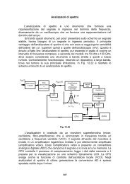
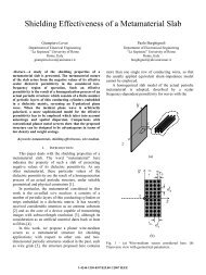
Fig. 1: I) <strong>FSO</strong> optical head; II) <strong>FSO</strong> site in southern Rome.Previous stu<strong>di</strong>es on the local micro-climate, withmeasurements made at the meteorological station located in A,confirmed the peculariatiy <strong>of</strong> the chosen site for urbanwireless communications experiments (see Fig. 2). The <strong>FSO</strong>experiment should last no less than two solar years, a period<strong>of</strong> interest from a scientific perspective.Fig. 2: Temperature and humi<strong>di</strong>ty histogram in Rome.The fSONA-SONAbeam ® 1250-E optical transceiverdevice has been recently installed in A and B (see Fig. 3). Itsmain characteristics are: weight <strong>of</strong> about 10 kg; structureoperating in the presence <strong>of</strong> wind gusts over 120 km/h andresistant to over 160 km/h; <strong>di</strong>mensions <strong>of</strong> 25×33×46 cm 3 ;power supply with 22÷57 VDC or 85÷260 VAC; safety withstandard IP66 (1550-nm is safe for human eyes); laser with 4transmitters <strong>of</strong> 160-mW peak power at 1550 nm; aperture<strong>di</strong>ameter <strong>of</strong> 20 cm; nominal maximum range in clear air up to5300 m; transmission rates (transparent and reclocked) up to1448 Mbs with transmission standards OC-3/STM-1, OC-12/STM-4, 270 Mbps, 1064 Mbps, Fast/Gig Ethernet.Together with the optical transreceiver, there will be alsoavailable at the site A: meteorological station (pressure,temperature, wind), raingauge, particle <strong>di</strong>sdrometer, opticalscintillometer, millimetre-wave ra<strong>di</strong>ometer, and visibilimeter.Fig. 3: fSONA-SONAbeam® 1250-E optical transceiver device.III. CHANNEL MODELLING<strong>FSO</strong> channel modeling requires to deal with the extinction<strong>of</strong> the laser beam power due to optical interactions withatmospheric particle <strong>di</strong>stributions, mainly aerosols, snow, fogand rain [5]. Only the latter two will be treated below. Ingeneral, the “extinction” law for any electromagnetic ra<strong>di</strong>ationintensity I (W m -2 sr -1 Hz -1 ) can be written as [8]:Irke( r')dr', 000 (0, r)r, I0,, e I e I t(0,r) (1)where r (km) is the range, () are the incidence angles, I 0 isthe incident intensity, k e (1/km) is the wavelength- andmeteorological-dependent extinction coefficient due toatmospheric gases and particle poly<strong>di</strong>spersions, the opticalthickness and t the intensity transmittance. The relation (1) isalso referred to as the “Beer–Lambert–Bouguer” law withinthe ra<strong>di</strong>ative transfer theory [8].A. Atmospheric attenuation due fog and rainThe main uncertainty to design an outdoor short-rangeoptical wireless link is the atmospheric attenuation, caused bythe absorption and scattering [5]-[7]. Water particles andcarbon <strong>di</strong>oxide mainly cause the absorption <strong>of</strong> optical signals,whereas fog, rain, snow and clouds cause the scattering <strong>of</strong>optical signals transmitted in free space. This scatteringprocesss causes the emitted light beam to deflect away fromthe intended receiver.Fog is the most deterrent attenuating factor for <strong>FSO</strong> links[6]. Fog causes significant path attenuation <strong>of</strong> optical signalsfor considerable amount <strong>of</strong> time due to the fact that the size <strong>of</strong>fog particles is comparable to the transmission wavelengths <strong>of</strong>optical and near infrared waves [7]. Optical attenuations incase <strong>of</strong> spherical fog droplets can be accurately pre<strong>di</strong>cted byapplying the “Mie scattering” theory [8]. The latter, however,involves requires a detailed information <strong>of</strong> fog parameters,like particle size, refractive index, particle size <strong>di</strong>stribution,which may not be available at a particular site <strong>of</strong> installation.An alternate approach is to pre<strong>di</strong>ct fog attenuation, basedon the visibility range information [9]-[12]. The visibilityrange r V is the <strong>di</strong>stance r to an object where the image contrastdrops to a percentage <strong>of</strong> what it would be if the object werenearby. The 550-nm wavelength is commonly used tomeasure the reference visibility range as and routinelyavailable at meteorological stations and airports as at thiswavelength the atmosphere has maximum transmittance.To pre<strong>di</strong>ct fog attenuation, based on visibility rangeestimate, three models are widely used: the Kruse et al. [10],Kim et al. [11] and Al-Naboulsi et al. [12] models. As anexample, from (1) the fog specific attenuation coefficient Fog(dB/km) for both the Kim and Kruse <strong>FSO</strong> models, assuming auniform me<strong>di</strong>um, is given by [10], [11]:qln 1/ t0th Fog 4.343ker (2)V 0