IQ SensorNet SensoLyt Sensor User Manual - YSI.com
IQ SensorNet SensoLyt Sensor User Manual - YSI.com
IQ SensorNet SensoLyt Sensor User Manual - YSI.com

Create successful ePaper yourself
Turn your PDF publications into a flip-book with our unique Google optimized e-Paper software.
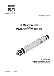
Operating manual<strong>IQ</strong> SENSOR NET<strong>SensoLyt</strong> ® 700 <strong>IQ</strong> (SW)<strong>SensoLyt</strong> 700 <strong>IQ</strong><strong>SensoLyt</strong> 700 <strong>IQ</strong> SW<strong>IQ</strong> SENSOR NET pH/ORP sensorba76006e01 01/2012
<strong>SensoLyt</strong> ® 700 <strong>IQ</strong> (SW)NoteFor the most recent version of the manual, please visit www.ysi.<strong>com</strong>.ContactCopyright<strong>YSI</strong>1725 Brannum LaneYellow Springs, OH 45387 USATel: +1 937-767-7241800-765-4974Email: environmental@ysi.<strong>com</strong>Internet: www.ysi.<strong>com</strong>© 2012 Xylem Inc.2 ba76006e01 01/2012
<strong>SensoLyt</strong> ® 700 <strong>IQ</strong> (SW)Contents<strong>SensoLyt</strong> ® 700 <strong>IQ</strong> (SW) - Contents1 Overview . . . . . . . . . . . . . . . . . . . . . . . . . . . . . . . . . . . . 1-11.1 How to use this <strong>com</strong>ponent operating manual . . . . . . . . 1-11.2 Structure of the <strong>SensoLyt</strong> ® 700 <strong>IQ</strong> (SW) . . . . . . . . . . . . 1-21.3 Re<strong>com</strong>mended fields of application . . . . . . . . . . . . . . . . 1-22 Safety . . . . . . . . . . . . . . . . . . . . . . . . . . . . . . . . . . . . . . 2-12.1 Authorized use . . . . . . . . . . . . . . . . . . . . . . . . . . . . . . . . 2-22.2 General safety instructions . . . . . . . . . . . . . . . . . . . . . . . 2-23 Commissioning . . . . . . . . . . . . . . . . . . . . . . . . . . . . . . 3-13.1 Scope of delivery . . . . . . . . . . . . . . . . . . . . . . . . . . . . . . 3-13.2 Installation . . . . . . . . . . . . . . . . . . . . . . . . . . . . . . . . . . . 3-13.3 Commissioning / Getting the instrument ready formeasuring . . . . . . . . . . . . . . . . . . . . . . . . . . . . . . . . . 3-33.4 <strong>SensoLyt</strong> ® 700 <strong>IQ</strong> (SW) setting table . . . . . . . . . . . . . . . 3-64 Measuring / Operation . . . . . . . . . . . . . . . . . . . . . . . . . 4-14.1 Measuring . . . . . . . . . . . . . . . . . . . . . . . . . . . . . . . . . . . 4-14.2 Calibration . . . . . . . . . . . . . . . . . . . . . . . . . . . . . . . . . . . 4-14.2.1 General information on calibration . . . . . . . . . . 4-14.2.2 Calibration with CAL TEC AUTO . . . . . . . . . . . 4-34.2.3 Calibration with CAL CON 2P . . . . . . . . . . . . . . 4-44.2.4 Calibration with CAL CON 1P . . . . . . . . . . . . . . 4-54.2.5 Calibration result . . . . . . . . . . . . . . . . . . . . . . . . 4-64.2.6 Calibration history . . . . . . . . . . . . . . . . . . . . . . . 4-74.2.7 Reactivation of the last valid calibration . . . . . . 4-85 Maintenance and changing the electrode . . . . . . . . . 5-15.1 General maintenance instructions . . . . . . . . . . . . . . . . . 5-15.2 Replacing the <strong>com</strong>bination electrode . . . . . . . . . . . . . . . 5-25.3 Disposal . . . . . . . . . . . . . . . . . . . . . . . . . . . . . . . . . . . . . 5-46 Replacement parts and accessories . . . . . . . . . . . . . 6-16.1 Combination electrodes . . . . . . . . . . . . . . . . . . . . . . . . . 6-16.2 General accessories . . . . . . . . . . . . . . . . . . . . . . . . . . . 6-17 What to do if... . . . . . . . . . . . . . . . . . . . . . . . . . . . . . . . 7-1ba76006e01 01/20120 - 1
Contents<strong>SensoLyt</strong> ® 700 <strong>IQ</strong> (SW)8 Technical data . . . . . . . . . . . . . . . . . . . . . . . . . . . . . . . 8-18.1 Measurement characteristics . . . . . . . . . . . . . . . . . . . . .8-18.2 Application characteristics . . . . . . . . . . . . . . . . . . . . . . .8-18.3 General data . . . . . . . . . . . . . . . . . . . . . . . . . . . . . . . . . .8-38.4 Electrical data . . . . . . . . . . . . . . . . . . . . . . . . . . . . . . . . .8-49 Contact Information . . . . . . . . . . . . . . . . . . . . . . . . . . . 9-19.1 Ordering & Technical Support . . . . . . . . . . . . . . . . . . . .9-19.2 Service Information . . . . . . . . . . . . . . . . . . . . . . . . . . . . .9-110 Indexes . . . . . . . . . . . . . . . . . . . . . . . . . . . . . . . . . . . . 10-110.1 Explanation of the messages . . . . . . . . . . . . . . . . . . . .10-110.1.1 Error messages . . . . . . . . . . . . . . . . . . . . . . . .10-110.1.2 Info messages . . . . . . . . . . . . . . . . . . . . . . . . .10-210.2 Status info . . . . . . . . . . . . . . . . . . . . . . . . . . . . . . . . . . .10-30 - 2 ba76006e01 01/2012
<strong>SensoLyt</strong> ® 700 <strong>IQ</strong> (SW)Overview1 Overview1.1 How to use this <strong>com</strong>ponent operating manualStructure of the<strong>IQ</strong> SENSOR NET operatingmanual<strong>IQ</strong> <strong>Sensor</strong> Net Operating <strong>Manual</strong>SystemOperating<strong>Manual</strong>(Ring Binder)<strong>IQ</strong> <strong>Sensor</strong>Operating<strong>Manual</strong>M<strong>IQ</strong> ModuleOperating<strong>Manual</strong>M<strong>IQ</strong> TerminalOperating<strong>Manual</strong>Component Operating <strong>Manual</strong>sFig. 1-1Structure of the <strong>IQ</strong> SENSOR NET operating manualThe <strong>IQ</strong> SENSOR NET operating manual has a modular structure like the<strong>IQ</strong> SENSOR NET system itself. It consists of a system operating manualand the operating manuals of all the <strong>com</strong>ponents used.Please file this <strong>com</strong>ponent operating manual in the ring binder of thesystem operating manual.ba76006e01 01/20121 - 1
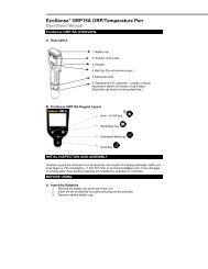
Overview<strong>SensoLyt</strong> ® 700 <strong>IQ</strong> (SW)1.2 Structure of the <strong>SensoLyt</strong> ® 700 <strong>IQ</strong> (SW)1 2 3 4 5Fig. 1-2Structure of the pH/ORP sensor (example, <strong>SensoLyt</strong> ® 700 <strong>IQ</strong>)1 Protective hood2 Temperature sensor3 Combination electrode (not contained in the scope of delivery)4 Electrode holder5 <strong>Sensor</strong> shaftNoteThe pH <strong>com</strong>bination electrodes that can be used are available asaccessories (see chapter 6 REPLACEMENT PARTS AND ACCESSORIES).Screening of the pH/ORP sensorGlass breakagemonitoringThe <strong>com</strong>bination electrode and the <strong>SensoLyt</strong> 700 <strong>IQ</strong> pH/ORP sensortogether with the <strong>IQ</strong> SENSOR NET system form a measuring system thatis protected to a high degree against low and high frequencyinterference as well as against the indirect effects of lightning strikes.The sensor is equipped with a SensCheck function for monitoring glassbreakage.1.3 Re<strong>com</strong>mended fields of applicationIn conjunction with the <strong>SensoLyt</strong> SEA, <strong>SensoLyt</strong> DWA and<strong>SensoLyt</strong> ‚ ECA pH <strong>com</strong>bination electrodes as well as the <strong>SensoLyt</strong> PtA ORP <strong>com</strong>bination electrode, the <strong>SensoLyt</strong> 700 <strong>IQ</strong> pH/ORPsensor is suitable for stationary pH or ORP measurement in thefollowing ranges.<strong>SensoLyt</strong> 700 <strong>IQ</strong><strong>SensoLyt</strong> 700 <strong>IQ</strong> SWStationary measurements in water/wastewater applications.Stationary measurements in seawater and brackish water,aquaculture.1 - 2 ba76006e01 01/2012
<strong>SensoLyt</strong> ® 700 <strong>IQ</strong> (SW)Safety2 SafetyThis <strong>com</strong>ponent operating manual contains special instructions thatmust be followed in the operation of the <strong>SensoLyt</strong> ® 700 <strong>IQ</strong> (SW) pH/ORP sensor. Thus, it is essential to read this <strong>com</strong>ponent operatingmanual before carrying out any work using this sensor. In addition tothis manual, the SAFETY chapter of the <strong>IQ</strong> SENSOR NET systemoperating manual must be followed.Always keep this <strong>com</strong>ponent operating manual together with thesystem operating manual and any other <strong>com</strong>ponent operating manualsin the vicinity of the <strong>IQ</strong> SENSOR NET system.Special userqualificationsGeneral safetyinstructionsThe pH/ORP sensor was developed for applications in onlinemeasurement - essentially in the field of wastewater treatment. Thus,we assume that the operators are familiar with the necessaryprecautions to take when dealing with chemicals as a result of theirprofessional training and experience.Safety instructions in this operating manual can be recognized by thewarning symbol (triangle) in the left column. The signal word (e. g."CAUTION") indicates the level of the danger:WARNINGindicates instructions that must be followed precisely in order toprevent serious dangers to persons.CAUTIONindicates instructions that must be followed precisely in order toavoid slight injuries or damage to the instrument or theenvironment.Other labelsNoteindicates notes that draw your attention to special features.Noteindicates cross-references to other documents, e.g. operatingmanuals.ba76006e01 01/20122 - 1
Safety<strong>SensoLyt</strong> ® 700 <strong>IQ</strong> (SW)2.1 Authorized useThe authorized use of the <strong>SensoLyt</strong> ® 700 <strong>IQ</strong> (SW) <strong>com</strong>prises its use asa pH/ORP sensor together with a pH <strong>com</strong>bination electrode or ORP<strong>com</strong>bination electrode in the <strong>IQ</strong> SENSOR NET.The technical specifications according to chapter 8 TECHNICAL DATAmust be observed. Only operation according to the instructions in thisoperating manual is authorized.Any other use is considered to be unauthorized. Unauthorized useinvalidates any claims with regard to the guarantee.CAUTIONOnly connect and operate the sensor together with <strong>IQ</strong> SENSOR NETaccessories.2.2 General safety instructionsThe sensor left the factory in a safe and secure technical condition.Function andoperational safetyThe failure-free function and operational safety of thesensor is only guaranteed if the generally applicable safety measuresand the special safety instructions in this operating manual are followedduring its use.The failure-free function and operational safety of the sensor is onlyguaranteed under the environmental conditions that are specified inchapter 8 TECHNICAL DATA.The specified temperature (chapter 8 TECHNICAL DATA) must bemaintained during the operation and transport of the sensor. Protectthe sensor, particularly against frost or overheating.CAUTIONThe sensor may only be opened by specialists authorized by <strong>YSI</strong>.2 - 2 ba76006e01 01/2012
<strong>SensoLyt</strong> ® 700 <strong>IQ</strong> (SW)SafetySafe operationIf safe operation is no longer possible, the sensor must be taken out ofoperation and secured against inadvertent operation.Safe operation is no longer possible if the sensor:• has been damaged in transport• has been stored under adverse conditions for a lengthy period oftime• is visibly damaged• no longer operates as described in this manual.If you are in any doubt, contact the supplier of your sensor.Obligations of theoperatorThe operator of the sensor must ensure that the following rules andregulations are followed when dealing with hazardous substances:• EEC directives for protective labor legislation• National protective labor legislation• Safety regulations• Safety data sheets of the chemical manufacturer.ba76006e01 01/20122 - 3
Safety<strong>SensoLyt</strong> ® 700 <strong>IQ</strong> (SW)2 - 4 ba76006e01 01/2012
<strong>SensoLyt</strong> ® 700 <strong>IQ</strong> (SW)Commissioning3 Commissioning3.1 Scope of delivery• <strong>SensoLyt</strong> ® 700 <strong>IQ</strong> (SW)• The sensor is fitted with a protective hood and protective caps• Operating manual.3.2 InstallationConnection cableA sensor connection cable of the SAC<strong>IQ</strong> or SAC<strong>IQ</strong> SW type is requiredto connect the sensor. The cable is available in different lengths.Compared to the standard model SAC<strong>IQ</strong>, the SAC<strong>IQ</strong> SW sensorconnection cable is optimized regarding its corrosion resistance inseawater and brackish water and adapted for use in conjunction withthe <strong>SensoLyt</strong> ® 700 <strong>IQ</strong> SW. Information on this and other<strong>IQ</strong> SENSOR NET accessories is given in the <strong>YSI</strong> catalog and on theInternet.NoteHow to connect the SAC<strong>IQ</strong> (SW) sensor connection cable to theterminal strip of an M<strong>IQ</strong> module is described in chapter 3 INSTALLATIONof the <strong>IQ</strong> SENSOR NET system operating manual.CAUTIONThe <strong>SensoLyt</strong> ® 700 <strong>IQ</strong> pH/ORP sensor unit may only be immersedin conjunction with a mounted <strong>com</strong>bination electrode. Moisturemust be prevented from penetrating the pH/ORP sensor duringthe replacement of the electrode as, otherwise, the sensor couldbe destroyed. Which electrodes can be used in conjunction withthe <strong>SensoLyt</strong> ® 700 <strong>IQ</strong> pH/ORP sensor unit is given in section6.1 COMBINATION ELECTRODES.Are the plugconnections dry?Before connecting the sensor and sensor connection cable, pleasemake sure that the plug connections are dry. If moisture gets into theplug connections, first dry the plug connections (dab them dry or blowthem dry using <strong>com</strong>pressed air).NoteDo not suspend the sensor on the sensor connection cable. Use anarmature or electrode holder. Information on this and other <strong>IQ</strong> SENSORNET accessories is given in the <strong>YSI</strong> catalog and on the Internet.ba76006e01 01/20123 - 1
Commissioning<strong>SensoLyt</strong> ® 700 <strong>IQ</strong> (SW)Connecting the sensorto the sensorconnection cable1 Take the protective caps off the plug connections of the sensorand the SAC<strong>IQ</strong> (SW) sensor connection cable and keep themsafe.2 Plug the jack of the SAC<strong>IQ</strong> (SW) sensor connection cable ontothe plug head connector of the sensor. At the same time, rotatethe socket so that the pin in the plug head connector (1) clicksinto one of the two holes in the jack.3 Then, screw the coupling ring (2) of the sensor connectioncable onto the sensor up to the stop.SAC<strong>IQ</strong>21Fig. 3-1Connecting the sensor3 - 2 ba76006e01 01/2012
<strong>SensoLyt</strong> ® 700 <strong>IQ</strong> (SW)Commissioning3.3 Commissioning / Getting the instrument ready formeasuringNoteA KCI-filled plastic cap is mounted on the tip of the sensor to keep the<strong>com</strong>bination electrode active during storage (or during longer pausesin measuring). The cap must be removed for measuring.Mounting the<strong>com</strong>bination electrode1 Unscrew the protective hood from the sensor.2 Pull off the blind plug from the plug head socket of the sensor.3 Screw off the protective cap of the plug head connector of the<strong>com</strong>bination electrode.ba76006e01 01/20123 - 3
Commissioning<strong>SensoLyt</strong> ® 700 <strong>IQ</strong> (SW)4 Screw the <strong>com</strong>bination electrode into the plug head socket ofthe sensor.5 Push the unit into the sensor up to the stop.CAUTIONPush the connected <strong>com</strong>bination electrode into the sensor rightup to the stop so that the connection is watertight. Leaks couldlead to the destruction of the sensor.6 Pull the KCI-filled plastic cap off the <strong>com</strong>bination electrode formeasuring.3 - 4 ba76006e01 01/2012
<strong>SensoLyt</strong> ® 700 <strong>IQ</strong> (SW)Commissioning7 Screw the protective hood onto the sensor.8 If required, assign a user-defined name to the sensor (seerelevant <strong>IQ</strong> SENSOR NET system operating manual).9 Set the sensor (see section 3.4).10 Calibrate the sensor (see section 4.2).ba76006e01 01/20123 - 5
Commissioning<strong>SensoLyt</strong> ® 700 <strong>IQ</strong> (SW)3.4 <strong>SensoLyt</strong> ® 700 <strong>IQ</strong> (SW) setting tableSetting Selection/values ExplanationMeasuring mode• mV• pHTemperature mode • °C• °FCalibrationprocedure(only in pHmeasuring mode)Calibration(software version2.18 or higher)• CAL TEC AUTO• CAL CON 2P• CAL CON 1P• valid• invalid• last valid• active• abortUnit of the measured values on themeasured value display.Unit of the measured temperature value(Celsius, Fahrenheit).• Simplified 2-point calibration using anytwo different buffer solutions. Thenominal values of the buffer solutionsare stored in the sensor. This makesthe manual entry of the nominal valuesredundant.• 2-point calibration using the followingbuffer solutions:1.) pH 7.0 ± 0.52.) any pH valueThe nominal values of the buffersolutions must be entered.• 1-point calibration using any singlebuffer solution. The nominal value ofthe buffer solution must be entered.Displays and determines which calibrationdata the measured value calculation isbased on. The active calibration is displayedin the calibration history (see section4.2.6).valid indicates that a valid calibration isavailable. The value cannot be changed.invalid is displayed if the last calibration isinvalid and the sensor is blocked for measurement.In this case, you can switch tothe values of the last valid calibration, provideda valid calibration is available in thesensor. Thus you activate the last validcalibration stored in the sensor the nexttime you exit the setting table with Saveand quit. The next time the setting table isopened, valid is displayed.3 - 6 ba76006e01 01/2012
<strong>SensoLyt</strong> ® 700 <strong>IQ</strong> (SW)Commissioningactive indicates that the sensor is beingcalibrated. If Cancel is selected, the activecalibration procedure is canceled as soonas the setting table is exited with Save andquit.ORP shift(only in mVmeasuring mode)TemperatureadjustmentSave and quitQuit-100 mV ... +100 mV You can set the ORP zero point here.-1.5 K ... +1.5 K The temperature <strong>com</strong>pensation functionenables the temperature sensor to bebalanced against a reference temperaturemeasurement (displacement of the zeropoint by ±1.5 K).Notes:• Due to the thermal capacity of thesensor, it is necessary to place it in acontainer with at least 2 liters of water.• Leave the sensor in this container for atleast 15 minutes, or in the case oftemperature differences between thewater and sensor > 10 K for at least 1hour, while stirring occasionally. Thencarry out the balancing procedure.The system confirms the saving of thesettings and the display switches to thenext higher level.The display switches to the next higherlevel without saving the new settings.Carrying out settingsUsing s, switch from the measured value display to the main menu ofthe settings. Then navigate to the setting menu (setting table) of thesensor. The exact procedure is given in the relevant <strong>IQ</strong> SENSOR NETsystem operating manual.ba76006e01 01/20123 - 7
Commissioning<strong>SensoLyt</strong> ® 700 <strong>IQ</strong> (SW)3 - 8 ba76006e01 01/2012
<strong>SensoLyt</strong> ® 700 <strong>IQ</strong> (SW)Measuring / Operation4 Measuring / Operation4.1 MeasuringWARNINGContact with the sample can lead to danger to the user!Depending on the type of sample, suitable protective measuresmust be taken (protective clothing, protective goggles, etc.).NoteCalibrate the <strong>com</strong>bination electrode with the sensor and the measuringsystem before measuring and at regular intervals (depending on theapplication).NotePlease pay attention to:• the minimum immersion depth of the sensor (> 40 mm)• the measuring range of the electrode used (see operating manual ofthe electrode).4.2 Calibration4.2.1 General information on calibrationWhy calibrate?When to calibrate?Calibration procedureDuring the operation of a pH electrode, the slope and asymmetry of theelectrode changes with time. The calibration procedure determines thecurrent slope and asymmetry of the electrode.Calibrate before measuring and at regular intervals (depending on theapplication).The CAL TEC AUTO calibration procedure enables a fully automaticcalibration using buffer solutions. Ordering information on buffersolutions is given in chapter 6 REPLACEMENT PARTS AND ACCESSORIES.The CAL CON 2P calibration procedure enables conventional twopointcalibration using using 2 different buffer solutions (first buffersolution pH 7.0 ± 0.5, second buffer solution with any pH value).The CAL CON 1P calibration procedure enables conventional singlepointcalibration with any single buffer solution.Calibration record /calibration historyThe result of a calibration is stored in the calibration record andcalibration history respectively and can be viewed afterwards (seerespective <strong>IQ</strong> SENSOR NET system operating manual).ba76006e01 01/20124 - 1
Measuring / Operation<strong>SensoLyt</strong> ® 700 <strong>IQ</strong> (SW)Maintenance conditionGeneral course of acalibration on the<strong>IQ</strong> SENSOR NETDuring calibration the sensor is in the so-called maintenance condition.This means all linked outputs retain their momentary state. Afterfinishing calibration the maintenance condition has to be switched offmanually. For more detailed information on the maintenance conditionplease refer to the respective <strong>IQ</strong> SENSOR NET system operatingmanual.Generally, calibration on the <strong>IQ</strong> SENSOR NET is carried out as follows.System specific details are given in the respective <strong>IQ</strong> SENSOR NETsystem operating manual.NoteBefore starting make sure the correct calibration procedure is set (seesection 3.4 SENSOLYT® 700 <strong>IQ</strong> (SW) SETTING TABLE).1 Switch to the measured value display with m and select thesensor to be calibrated.2 Call up calibration with c.The next step switches on the maintenance condition for thesensor. A corresponding note appears on the display.3 Confirm the note with g.The maintenance condition is active.The menu-guided calibration routine starts.Follow the instructions on the display.After the calibration routine is finished, the measured valuedisplay appears again (the measured value flashes becausethe sensor is still in the maintenance condition).4 If the calibration was successful, bring the sensor into themeasuring position.5 Wait for a stable measured value.6 Switch off the maintenance condition.4 - 2 ba76006e01 01/2012
<strong>SensoLyt</strong> ® 700 <strong>IQ</strong> (SW)Measuring / Operation4.2.2 Calibration with CAL TEC AUTOMessages displayed during calibration with CAL TEC AUTODisplay* Have any two technical buffersolutions ready.* Rinse the sensor.* Immerse the sensor in the firstbuffer solution.* Wait for a stable measuredvalue.* Rinse the sensor.* Immerse the sensor in thesecond buffer solution.* Wait for a stable measuredvalue.Successfully calibrated.End of the CAL TEC AUTOcalibration.ExplanationYou can use any two differentbuffer solutions to do this.Confirm with g.Follow the instructions on thedisplay. As soon as a stablemeasured value is reached, thenext display appears.Follow the instructions on thedisplay. As soon as a stablemeasured value is reached, thenext display appears.The values determined for Slopeand Asymmetry potential aredisplayed.The calibration is <strong>com</strong>plete.Confirm with g.The display returns to themeasured value display.ba76006e01 01/20124 - 3
Measuring / Operation<strong>SensoLyt</strong> ® 700 <strong>IQ</strong> (SW)4.2.3 Calibration with CAL CON 2PMessages displayed during two-point calibration with CAL CON 2PDisplay* Have buffer pH 7.0 ± 0.5 andany second buffer solution ready.* Rinse the sensor.* Immerse the sensor in the firstbuffer solution pH 7.0 ± 0.5.* Wait for a stable measuredvalue.* Enter the pH value of the firstbuffer solution.* Rinse the sensor.* Immerse the sensor in the secondbuffer solution.* Wait for a stable measuredvalue.* Enter the pH value of the secondbuffer solution.Successfully calibrated.End of the CAL CON 2Pcalibration.ExplanationYou can use two buffer solutionsof which the pH values accordingto the actual temperature areknown:– first buffer solutionpH 7,0 ± 0,5– second buffer solution withany pH valueFollow the instructions on thedisplay. As soon as a stablemeasured value is reached, thenext display appears.Select the pH value of the firstbuffer solution according to thedisplayed temperature with dand confirm with g.Follow the instructions on thedisplay. As soon as a stablemeasured value is reached, thenext display appears.Select the pH value of the secondbuffer solution according to thedisplayed temperature with dand confirm with g.The values determined for Slopeand Asymmetry potential aredisplayed.The calibration is <strong>com</strong>plete.Confirm with g.The display returns to themeasured value display.4 - 4 ba76006e01 01/2012
<strong>SensoLyt</strong> ® 700 <strong>IQ</strong> (SW)Measuring / Operation4.2.4 Calibration with CAL CON 1PMessages displayed during the single-point calibration withCAL CON 1PDisplayExplanation* Have any buffer solution ready. You can use any buffer solutionthe pH value of which is known atthe current temperature.* Rinse the sensor.* Immerse the sensor in the buffersolution.* Wait for a stable measuredvalue.* Enter the pH value of the buffersolution.Confirm entered data andcontinue calibrationSuccessfully calibrated.End of the CAL CON 1Pcalibration.Follow the instructions on thedisplay. As soon as a stablemeasured value is reached, thenext display appears.Enter the pH value with d.Confirm with g. Themeasurement of the buffersolution begins.The values determined for Slopeand Asymmetry potential aredisplayed.The calibration is <strong>com</strong>plete.Confirm with g.The display returns to themeasured value display.ba76006e01 01/20124 - 5
Measuring / Operation<strong>SensoLyt</strong> ® 700 <strong>IQ</strong> (SW)4.2.5 Calibration resultCalibration evaluationAfter calibrating the system automatically evaluates the calibration dataand current state of the sensor. The asymmetry and slope areevaluated separately. The values must be within the following ranges:Slope: -50 ... -62 mV/pHAsymmetry: -45 mV ... +45 mVIf one of both values is outside the specified range, the calibration isevaluated as unsuccessful, i. e. the sensor could not be calibrated.A calibration can have the following results:Possible results of thecalibrationDisplay after thecalibrationMeasured value displayLog book entries(meaning/actions)<strong>Sensor</strong> was successfully calibrated.For the calibration data, see the calibrationhistory."----" <strong>Sensor</strong> could not be calibrated.<strong>Sensor</strong> blocked for measurement.– Service the sensor immediately(see operating manual).– View the calibration history.– Check the calibration conditions andcalibration standard.NoteInformation on the contents and structure of the log book, and how tocall it up, is given in the LOG BOOK chapter of the <strong>IQ</strong> SENSOR NETsystem operating manual.4 - 6 ba76006e01 01/2012
<strong>SensoLyt</strong> ® 700 <strong>IQ</strong> (SW)Measuring / Operation4.2.6 Calibration historyCalibration history(available in the<strong>IQ</strong> SENSOR NETsystem 2020 XT only)actual activecalibrationchronological listwith the lastcalibrationsFig. 4-1Calibration history <strong>SensoLyt</strong> ® 700 <strong>IQ</strong> (SW)The calibration history contains the following information:• Date of the calibration• Slope [mv/pH]• Asymmetry potential [mV]• Rating of the calibration:– o.k.: Calibration was successful.The new calibration values are used for the measurements.– Error: Calibration was not successful.The <strong>Sensor</strong> is blocked for measurement.ba76006e01 01/20124 - 7
Measuring / Operation<strong>SensoLyt</strong> ® 700 <strong>IQ</strong> (SW)4.2.7 Reactivation of the last valid calibrationThe <strong>SensoLyt</strong> ® 700 <strong>IQ</strong> (SW) enables you to reactivate the last validcalibration when needed. Thereby, it is possible to continue withmeasurements, when a calibration failed or it is assumed that optimalcalibration conditions were not met.NoteThe reactivation of former calibration data is only a temporary solution.Please consider, that thereby possibly wrong measurement values areproduced. Please check correct functioning of the sensor by performinga function check and/ or a user calibration.Reactivating the lastvalid calibration data1 Open the the setting table (see section 3.4).2 Choose in the menue item Calibration the setting letzte gültigeand quit the setting table afterwards with Save and quit.4 - 8 ba76006e01 01/2012
<strong>SensoLyt</strong> ® 700 <strong>IQ</strong> (SW)Maintenance and changing the electrode5 Maintenance and changing the electrode5.1 General maintenance instructionsThe <strong>SensoLyt</strong> ® 700 <strong>IQ</strong> (SW) pH/ORP sensor operates maintenancefree.NotePlease read the maintenance of the <strong>com</strong>bination electrode in therelevant operating manual of the electrode.WARNINGContact with the sample can lead to danger to the user!Depending on the type of sample, suitable protective measuresmust be taken (protective clothing, protective goggles, etc.).CAUTIONIf the glass of the pH electrode breaks, there is a danger of cutsfrom the splinters of glass!NoteWe do not re<strong>com</strong>mend unscrewing the sensor from the sensorconnection cable when changing the electrode. Otherwise, moistureand/or dirt can get into the plug connection where they can causecontact problems.If you would like to disconnect the sensor from the sensor connectioncable, please note the following points:• Before disconnecting the sensor from the SAC<strong>IQ</strong> (SW) sensorconnection cable, remove any larger pieces of contamination fromthe sensor, particularly in the area of the plug connection (brush itoff in a bucket of tapwater, wash it off with a hose or wipe it off witha cloth).• Unscrew the sensor from the SAC<strong>IQ</strong> (SW) sensor connection cable.• Always place a protective cap on the plug head of the sensor and onthe SAC<strong>IQ</strong> (SW) sensor connection cable so that no moisture or dirtcan get into the contacting surfaces.• In corrosive environments close the dry socket of the sensorconnection cable with the SAC<strong>IQ</strong>-Plug protective screw cap in orderto protect the electrical contacts from corrosion. The protective capis available as an accessory (see section 6.2 GENERALACCESSORIES). It is included in the standard scope of delivery of theSAC<strong>IQ</strong> SW sensor connection cable.ba76006e01 01/20125 - 1
Maintenance and changing the electrode<strong>SensoLyt</strong> ® 700 <strong>IQ</strong> (SW)5.2 Replacing the <strong>com</strong>bination electrodeIf it is necessary to replace the <strong>com</strong>bination electrode, proceed asfollows:1 Unscrew the protective hood from the sensor.2 Use the protective hood as a tool to lever out the <strong>com</strong>binationelectrode.3 Carefully pull out the <strong>com</strong>bination electrode until the plug headscrewed fitting can be seen.5 - 2 ba76006e01 01/2012
<strong>SensoLyt</strong> ® 700 <strong>IQ</strong> (SW)Maintenance and changing the electrode4 Unscrew the <strong>com</strong>bination <strong>com</strong>bination electrode from the plughead socket (for disposal, see section 5.3).5 Screw in a new <strong>com</strong>bination electrode.6 Push the unit into the sensor up to the stop.7 Pull the KCI-filled plastic cap off the <strong>com</strong>bination electrode formeasuring.ba76006e01 01/20125 - 3
Maintenance and changing the electrode<strong>SensoLyt</strong> ® 700 <strong>IQ</strong> (SW)8 Screw the protective hood onto the sensor.9 Calibrate the sensor and the electrode with the measuringsystem (see section 4.2 CALIBRATION).5.3 Disposal<strong>Sensor</strong>Combination electrodesWe re<strong>com</strong>mend disposing of the sensor as electronic refuse.If no official regulations apply to the contrary, used and defective<strong>com</strong>bination electrodes can be treated as household waste.5 - 4 ba76006e01 01/2012
<strong>SensoLyt</strong> ® 700 <strong>IQ</strong> (SW)Replacement parts and accessories6 Replacement parts and accessories6.1 Combination electrodespH <strong>com</strong>binationelectrodesModel<strong>SensoLyt</strong> ® SEA<strong>SensoLyt</strong> ® DWA<strong>SensoLyt</strong> ® ECA<strong>SensoLyt</strong> ® SEA-HPOrder no.109 115Y109 119Y109 117Y109 118YORP <strong>com</strong>binationelectrode<strong>SensoLyt</strong> ® PtA109 125Y6.2 General accessoriesBuffer solutions for<strong>SensoLyt</strong> ®pH electrodesDescription Model Order no.pH 4 (box of 6 pints) 3821 003821pH 7 (box of 6 pints) 3822 003822pH 10 (box of 6 pints) 3823 003823pH assorted (2 pints ea of 4, 7, and 10) 3824 603824Protective screw cap forsensor connection cableModelSAC<strong>IQ</strong>-PlugOrder no.480 065YNoteInformation on other <strong>IQ</strong> SENSOR NET accessories is given in the <strong>YSI</strong>catalog and on the Internet.ba76006e01 01/20126 - 1
Replacement parts and accessories<strong>SensoLyt</strong> ® 700 <strong>IQ</strong> (SW)6 - 2 ba76006e01 01/2012
<strong>SensoLyt</strong> ® 700 <strong>IQ</strong> (SW)What to do if...7 What to do if...No measured valueCauseRemedy– <strong>Sensor</strong> not connected – Connect the sensor– Unknown – Look in the log bookMeasurement does notfunctionCause– Watering cap still on theelectrodeRemedy– Pull off watering cap andcalibrate– Electrode not connected – Connect electrode– Liquid has penetrated thesensor– <strong>Sensor</strong> defective, send it back– <strong>Sensor</strong> not connected – Connect the sensor– Instrument setting incorrect – Correct instrument settingSystem cannot becalibratedCause– Slope of the electrode notwithin tolerance (see section4.2.5)Remedy– Condition the electrode– If the slope is still outside thetolerance: replace electrode– Slope of the electrode too low – Replace electrode– Asymmetry of the electrodetoo high– <strong>Sensor</strong> is operated with ORPelectrode– Replace electrode– Use pH electrodeba76006e01 01/20127 - 1
What to do if...<strong>SensoLyt</strong> ® 700 <strong>IQ</strong> (SW)Measurement providesimplausible measuredvaluesCauseRemedy– No calibration performed – Calibrate– Electrode not connected ordefective– Check electrode and electrodeconnection– Electrode contaminated – Clean electrode– Liquid has penetrated thesensor– <strong>Sensor</strong> defective, send it back– Instrument setting incorrect – Correct instrument setting(Measuring mode pH or mV)7 - 2 ba76006e01 01/2012
<strong>SensoLyt</strong> ® 700 <strong>IQ</strong> (SW)Technical data8 Technical data8.1 Measurement characteristicsMeasuring principlePotentiometric measurement using a <strong>com</strong>bination electrode;Integrated microprocessor electronics, shielded 2-wire connection forpower and data transmission.Measuring rangepHORP0.00 ... 14.00 pH (depending on the electrode)-2000 mV ... +2000 mV(depending on the electrode)ResolutionpHORP0.01 pH1 mVTemperaturemeasurementTemperature sensorMeasuring rangeAccuracyResolutionResponse time t 99 of thetemperature sensorintegrated NTC- 5 °C ... + 60 °C (23 ... 140 °F)± 0.5 K0.1 K< 15 sTemperature<strong>com</strong>pensationin the range 0 °C ... 60 °C (32 ... 140 °F)8.2 Application characteristicsTemperature rangeMeasuring mediumStorage/transport0 °C ... + 60 °C (32 ... 140 °F)- 5 °C ... + 65 °C (23 ... 149 °F)Allowed pH range of thetest sample4 ... 12ba76006e01 01/20128 - 1
Technical data<strong>SensoLyt</strong> ® 700 <strong>IQ</strong> (SW)Pressure resistanceMax. allowed overpressure (sensor including connection cable):with installed <strong>com</strong>bination electrode,<strong>SensoLyt</strong> ® SEA, DWA, PtAwith installed <strong>com</strong>bination electrode,<strong>SensoLyt</strong> ® ECAwith installed <strong>com</strong>bination electrode,<strong>SensoLyt</strong> ® SEA-HP10 6 Pa (10 bar) *6 x10 5 Pa (6 bar) *10 6 Pa (10 bar) *** temperature dependent (see safety instruction below)** in the entire temperature rangeThe <strong>SensoLyt</strong> ® 700 <strong>IQ</strong> (SW) meets the requirements according toarticle 3(3) of the directive, 97/23/EC ("pressure equipment directive").Immersion depthwith installed <strong>com</strong>bination electrode,<strong>SensoLyt</strong> ® SEA, DWA, PtAwith installed <strong>com</strong>bination electrode,<strong>SensoLyt</strong> ® ECAwith installed <strong>com</strong>bination electrode,<strong>SensoLyt</strong> ® SEA-HPmin. 40 mm; max. 100 m *min. 40 mm; max. 60 m *min. 40 mm; max. 100 m *** temperature dependent (see safety instruction below)** in the entire temperature rangeCAUTIONThe pressure resistance of the operable pH/ORP armature can bereduced by the pressure resistance of the <strong>com</strong>bination electrode.When selecting the <strong>com</strong>bination electrode make sure it is suitablefor the intended pressure and temperature range.Type of protection<strong>Sensor</strong> with installed <strong>com</strong>binationelectrode and including SAC<strong>IQ</strong> (SW)sensor connection cable<strong>Sensor</strong> plug head connector withoutsensor connection cable (sensor withinstalled <strong>com</strong>bination electrode)IP 68, 10 bar (10 6 Pa)IP 67Operating positionanyFields of application<strong>SensoLyt</strong> 700 <strong>IQ</strong><strong>SensoLyt</strong> 700 <strong>IQ</strong> SWStationary measurements in water/wastewater applicationsStationary measurements in seawaterand brackish water, aquaculture8 - 2 ba76006e01 01/2012
<strong>SensoLyt</strong> ® 700 <strong>IQ</strong> (SW)Technical data8.3 General dataDimensions<strong>SensoLyt</strong> 700 <strong>IQ</strong>:50840.0SAC<strong>IQ</strong> socket...<strong>SensoLyt</strong> 700 <strong>IQ</strong> SW:515Weight (without sensorconnection cable and<strong>com</strong>bination electrode)<strong>SensoLyt</strong> 700 <strong>IQ</strong>59.5<strong>SensoLyt</strong> 700 <strong>IQ</strong> SWapprox. 970 gapprox. 1800 gSAC<strong>IQ</strong> socket...Electrodes that can beintegratedpH <strong>com</strong>bination electrodesORP <strong>com</strong>bination electrodes<strong>SensoLyt</strong> ® SEA, SEA-HP, DWA,ECA<strong>SensoLyt</strong> ® PtAConnection techniqueConnection via the SAC<strong>IQ</strong> or SAC<strong>IQ</strong> SW sensor connection cableMaterialShaft– <strong>SensoLyt</strong> 700 <strong>IQ</strong>– <strong>SensoLyt</strong> 700 <strong>IQ</strong> SWProtective hoodElectrode holderTemperature sensor:– <strong>SensoLyt</strong> 700 <strong>IQ</strong>– <strong>SensoLyt</strong> 700 <strong>IQ</strong> SWV4A stainless steel 1.4571 *POMPVCPOMV4A stainless steel 1.4571 *V4A stainless steel 1.4571, KTLcoated* Stainless steel can be susceptible to corrosion at chlorideconcentrations of ≥ 500 mg/l and more. We re<strong>com</strong>mend to use SWsensors for applications in such test solutions.ba76006e01 01/20128 - 3
Technical data<strong>SensoLyt</strong> ® 700 <strong>IQ</strong> (SW)Material (Continued)Plug head housingPOMPlug, 3-pole ETFE (blue) Tefzel ®Automatic sensormonitoring(SensCheck function)Function for monitoring glass breakage in the pH electrodeInstrument safetyApplicable norms – EN 61010-1– UL 3111-1– CAN/CSA C22.2 No. 1010.18.4 Electrical dataNominal voltagePower consumptionProtective classMax. 24VDCvia the <strong>IQ</strong> SENSOR NET (for moredetails, see chapter TECHNICALDATA of the <strong>IQ</strong> SENSOR NETsystem operating manual)0.2 WIII8 - 4 ba76006e01 01/2012
<strong>SensoLyt</strong> ® 700 <strong>IQ</strong> (SW)Contact Information9 Contact Information9.1 Ordering & Technical SupportTelephone: (800) 897-4151(937) 767-7241Monday through Friday, 8:00 AM to 5:00 PM ETFax: (937) 767-1058Email:Mail:Internet:environmental@ysi.<strong>com</strong><strong>YSI</strong> Incorporated1725 Brannum LaneYellow Springs, OH 45387USAwww.ysi.<strong>com</strong>When placing an order please have the following information available:<strong>YSI</strong> account number (if available)Model number or brief descriptionQuantityName and Phone NumberBilling and shipping addressPurchase Order or Credit Card9.2 Service Information<strong>YSI</strong> has authorized service centers throughout the United States andInternationally. For the nearest service center information, please visitwww.ysi.<strong>com</strong> and click ‘Support’ or contact <strong>YSI</strong> Technical Supportdirectly at 800-897-4151.When returning a product for service, include the Product Return formwith cleaning certification. The form must be <strong>com</strong>pletely filled out for an<strong>YSI</strong> Service Center to accept the instrument for service. The ProductReturn form may be downloaded at www.ysi.<strong>com</strong> and clicking on the‘Support‘ tab.ba76006e01 01/20129 - 1
Contact Information<strong>SensoLyt</strong> ® 700 <strong>IQ</strong> (SW)9 - 2 ba76006e01 01/2012
<strong>SensoLyt</strong> ® 700 <strong>IQ</strong> (SW)Indexes10 Indexes10.1 Explanation of the messagesThis chapter contains a list of all the message codes and relatedmessage texts that can occur in the log book of the <strong>IQ</strong> SENSOR NETsystem for the <strong>SensoLyt</strong> ® 700 <strong>IQ</strong> (SW) sensor.NoteInformation on the contents and structure of the log book, and how tocall it up, is given in the LOG BOOK chapter of the <strong>IQ</strong> SENSOR NETsystem operating manual.NoteAll Message codes of the <strong>SensoLyt</strong> ® 700 <strong>IQ</strong> (SW) end up with "311".10.1.1 Error messagesMessage codeEA1311EA2311EA3311EC1311EI1311EI2311Message textMeas. range exceeded or undercut* Check process* Select other meas. range<strong>Sensor</strong> temperature too high!* Check process and application<strong>Sensor</strong> temperature too low!* Check process and application<strong>Sensor</strong> could not be calibrated,<strong>Sensor</strong> blocked for measurement* Check calibration conditions and calibration standard* View calibration history* Service sensor immediately(see operating manual)Operational voltage too low* Check installation and cable lengths, Follow installation instructions* Power unit(s) overloaded, add power unit(s)* Check terminal and module connections* Defective <strong>com</strong>ponents, replace <strong>com</strong>ponentsOperational voltage too low, no operation possible* Check installation and cable lengths, Follow installation instructions* Power unit(s) overloaded, add power unit(s)* Check terminal and module connections* Defective <strong>com</strong>ponents,replace <strong>com</strong>ponentsba76006e01 01/201210 - 1
Indexes<strong>SensoLyt</strong> ® 700 <strong>IQ</strong> (SW)Message codeES1311ESA311Message textComponent hardware defective* Contact serviceSensCheck: pH electrode defective, glass broken* Replace pH electrode10.1.2 Info messagesMessage codeIC1311IC4311II1311Message text<strong>Sensor</strong> has been successfully calibrated* For calibration data, see calibration historyDie letzte gültige Anwenderkalibrierung wurde aktiviert. KorrekteFunktion des <strong>Sensor</strong>s sicherstellen.Language not available,Default language German* Contact service10 - 2 ba76006e01 01/2012
<strong>SensoLyt</strong> ® 700 <strong>IQ</strong> (SW)Indexes10.2 Status infoThe status info is a coded piece of information on the current status ofa sensor. Each sensor sends this status info to the controller. Thestatus info of sensors consists of 32 bits, each of which can have thevalue 0 or 1.0 1 2 3 4 5 6 7 8 9 10 11 12 13 14 15Status info,general structure1 0 0 0 0 0 0 0 0 0 0 0 0 0 0 0 (general)0 0 0 0 0 0 0 0 0 0 0 0 0 0 0 0 (internal16 17 18 19 20 21 22 23 24 25 26 27 28 29 30 31The bits 0 - 15 are reserved for general information.The bits 16 - 21 are reserved for internal service information.You obtain the status info:• via a manual query in the Einstellungen/Settings/Service/List of all<strong>com</strong>ponents menu (see system operating manual)• by an automated query– of a superordinate process control (e. g. when connected to theProfibus)– from the <strong>IQ</strong> Data Server (see <strong>IQ</strong> SENSOR NET Software Packoperating manual)NoteThe evaluation of the status info, e.g. in the case of an automatedquery, has to be made individually for each bit.Status info<strong>SensoLyt</strong> ® 700 <strong>IQ</strong> (SW)Status bitBit 0Bit 1ExplanationComponent hardware defectiveSensCheck: pH electrode defective, glass brokenBit 2-31 -ba76006e01 01/201210 - 3
Indexes<strong>SensoLyt</strong> ® 700 <strong>IQ</strong> (SW)10 - 4 ba76006e01 01/2012
1725 Brannum LaneYellow Springs, Ohio 45387 USA+1 937-767-7241800-765-4974 (US)FAX (937) 767-1058Email: environmental@ysi.<strong>com</strong>Internet: www.ysi.<strong>com</strong>