IXP20 Web Interface User Manual - NO access
IXP20 Web Interface User Manual - NO access
IXP20 Web Interface User Manual - NO access

Create successful ePaper yourself
Turn your PDF publications into a flip-book with our unique Google optimized e-Paper software.
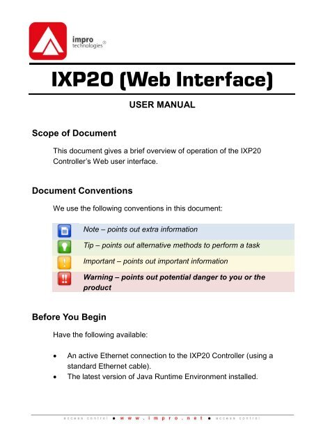
<strong>IXP20</strong> (<strong>Web</strong> <strong>Interface</strong>)USER MANUALScope of DocumentThis document gives a brief overview of operation of the <strong>IXP20</strong>Controller’s <strong>Web</strong> user interface.Document ConventionsWe use the following conventions in this document:Note – points out extra informationTip – points out alternative methods to perform a taskImportant – points out important informationWarning – points out potential danger to you or theproductBefore You BeginHave the following available:An active Ethernet connection to the <strong>IXP20</strong> Controller (using astandard Ethernet cable).The latest version of Java Runtime Environment installed.
1System SettingsInstalling Java Runtime Environment (JRE)1. Using Windows® Internet Explorer go to www.java.com.2. On the Home Page, click on the Free Java Download button.3. Click the Install button.4. At the Java Setup – Welcome dialog, click the Accept > button.5. At the Java Setup – Complete dialog, click the Finish button.6. Close Internet Explorer.7. Restart your PC.Starting the <strong>IXP20</strong> <strong>Web</strong> <strong>Interface</strong>Over a LANDo <strong>NO</strong>T open more than 1 instance of the <strong>Web</strong> <strong>Interface</strong> perController. When using the <strong>Web</strong> <strong>Interface</strong> with the TouchScreen Controller, ensure the screen is locked.If the <strong>Web</strong> Server resides on a Port other than Port 80, theURL becomes: http://ixp20:XX/. The XX highlighted in theURL refers to the new Port number.If your Controller connects direct to the PC, refer to page 24for information on <strong>access</strong>ing the <strong>Web</strong> <strong>Interface</strong>.1. In your Internet Browser go to http://ixp20/.2. At the Security Warning, click the Run button.3. Click the OK button.4. Select a location in which to save the Backup. Backup takes placeautomatically at startup, retaining the 5 most recent backups.ISC306-0-0-GB-01 August 2010 Page 2
5. Click the Open button.Over a WANWhen the <strong>Web</strong> <strong>Interface</strong> loads, it tries to connect to the Controller usingthe hostname and the Controller’s configured port. This hostname isonly valid on the LAN. If the <strong>Web</strong> <strong>Interface</strong> tries to connect to theController from another network or across the internet, provide therouter with a public static IP Address or a dynamic hostname andconfigure port forwarding.1. In your internet browser go to http://ixp20/.2. At the Controller Connection Error dialog, click the Yes button.3. Enter the Hostname or IP Address for the Controller.4. Click the OK button.5. Enter the Host Port for the Controller.6. Click the OK button.The next time you load the <strong>Web</strong> <strong>Interface</strong> on the same computer, loggedin as the same user, the values used for the alternative Hostname andalternative Host Port load as defaults into the Hostname and Host Porttextboxes.Date or Time Setup1. From the Main Menu, select System>Date/Time.2. Synchronise the <strong>IXP20</strong> Controller’s Date and Time to your PC byclicking the button.3. Set the Start and End Date for Daylight Savings using thebuttons.4. Set the time that Daylight Savings takes effect using the SwitchTime textbox.5. Set the duration of the Daylight Savings time shift using the ShiftDuration textbox.6. Click the button.ISC306-0-0-GB-01 August 2010 Page 3
Auto-IDPopulate tables and identify Terminals by performing an Auto-ID:1. From the Main Menu, select System>Auto ID.2. At the Auto-ID dialog, click the Yes button.3. Click the OK button.Door ConfigurationThe <strong>IXP20</strong> System supports a maximum of 8 Doors. Each Door has 3Door Mode Patterns (each with 4 time period allocations). The userinterface allows for configuration of each Door individually (labeled 1through 8) or configuration across all Doors at once (All label).General Settings1. From the Main Menu, select System>Doors.Figure 1 – Door Configuration DialogISC306-0-0-GB-01 August 2010 Page 4
2. With the Door Tab selected, in the Door Name textbox, assign asuitable name (maximum 16 characters).3. Select the Entry Reader using the drop-down list. Make yourselection from the list of displayed Readers.4. Select the Exit Reader using the drop-down list. Make yourselection from the list of displayed Readers.5. Add the Door to the Anti-passback (APB) Zone, by selecting theEnable APB checkbox.6. If necessary, de-select the Enable Door checkbox.7. Click the button.8. Click the OK button.Entry Settings1. Select the Entry Tab.2. Select the RTE Mode using the drop-down list, your optionsinclude: Normally Closed—sensor remains closed until opened by anoperator. Normally Open—sensor remains open until closed by anoperator.3. Edit the DOS Mode using the drop-down list, your options include: Normally Closed Normally Open4. Edit the DOS Usage using the drop-down list, your options include: Normal—alarm sounds if the Door remains open too long or ifthe Doors forced. Use this feature for monitoring real Dooropen states. Inhibit Reader—deactivates the Reader as long as the Door isopen; also there is no alarm for Doors forced open. Used todisable the reader while the Door remains open. Terminate Strike—deactivates the relay if Door is opened andclosed or forced. Use this feature where the lock must reengageonce the Door is closed.ISC306-0-0-GB-01 August 2010 Page 5
5. Set the Buzzer Volume (Allowed) using the drop-down list, selectfrom the options (Off, Soft, Medium and Loud) given.6. Set the Buzzer Volume (Denied) using the drop-down list, selectfrom the options (Off, Soft, Medium and Loud) given.7. Set the amount of time (in seconds) the Door stays open before analarm triggers using the Door Open Duration textbox. By default,the Door Open Duration is set to 0 meaning disenablement of theDoor Open Sensor (DOS).8. Set the amount of time (in seconds) the Door remains unlockedusing the Strike Duration (in seconds) textbox. The maximumStrike Duration is 999 999.9. By default end-of-line sensing is disabled, to enable end-of-linesensing on the Door Open Sensor (DOS), select the Enable DOSLine Sensing checkbox.10. Click the button.11. Click the OK button.Exit Settings1. Select the Exit Tab.2. Based on the similarity of the steps involved in Exit Settings, refer tothe Entry Settings section (page 5) for more information.Door Mode Pattern Configuration1. Select the Door Tab.2. Click the Pattern 1 button.ISC306-0-0-GB-01 August 2010 Page 6
Figure 2 – Door Mode Patterns Dialog3. Make your selection from the list of available <strong>access</strong> days (Mondayto Sunday or Holidays).4. For Slot 1, enter a Start and End Time.5. From the Mode drop-down list, select from the following: Locked—the Door is locked and cannot be overridden with anyTag. Tag—requires presentation of a Tag to open the Door. Tag + PIN—requires presentation of a Tag followed by entry ofa PIN-code to open the Door. PIN-codes range from 2 to65534. After entering the PIN-code, complete the entry bypressing the # key). Selecting this mode without connecting akeypad reader, applies Tag rules. Tag + Reason—requires presentation of a Tag followed byentry of a Reason Code to open the Door. Selecting this modewithout connecting a keypad reader, applies Tag rules. Open on First Tag—the door is opened when the first validTagholder presents their Tag and remains open. Open Now—the Door opens at specified time. A Tag is notrequired to open the Door.ISC306-0-0-GB-01 August 2010 Page 7
Personal Access Code—requires entry of a Personal AccessCode (PAC) to open the Door. Your Personal Access Codemay range from between 1 to 9999 followed by a # symbol.6. Repeat steps 4 and 5 for the remaining Slots.For example, set 3 time periods for a Door open between 8am and 5 pm, that is: Slot 1—Start Time 00:00 (default), Stop Time 07:59. Slot 2—Start Time 08:00, Stop Time 17:00. Slot 3—Start Time 17:01, Stop Time 23:59.7. Click the button.8. Set any remaining Door Mode Patterns.9. Click the button.10. Click the button.Access Group SetupThe Default Access Group allows ALL Tagholders <strong>access</strong> toALL Doors at ALL times. Therefore, create Access Groups torestrict or allow <strong>access</strong> as required.Add an Access Group1. From the Main Menu, select System>Access Groups.ISC306-0-0-GB-01 August 2010 Page 8
Figure 3 – Access Groups Dialog2. Click the button.3. Enter a suitable name in the Group Name textbox.4. Set the Start and Stop Time.5. Make your selection from the list of available Days.6. Make your selection from the displayed Doors.7. Click the button.8. Click the OK button.9. Click the button.Delete an Access Group1. From the Main Menu, select System>Access Groups.2. Select the Group Name for deletion.3. Click the button.4. Click the OK button.ISC306-0-0-GB-01 August 2010 Page 9
Edit an Access Group1. From the Main Menu, select System>Access Groups.2. Select the Access Group for editing.3. Based on the similarity of the steps involved in Editing an AccessGroup, refer to Add an Access Group (page 8) for more information.Holidays SetupAdd a Holiday1. From the Main Menu, select System>Holidays.2. Click the button.3. Enter a suitable name in the Holiday Name textbox.4. Set the Start Date by clicking the button.5. Set the End Date by clicking the button.6. Click the button.7. Close the dialog.Delete a Holiday1. From the Main Menu, select System>Holidays.2. Select the Holiday Name for deletion.3. Click the button.Edit a Holiday1. From the Main Menu, select System>Holidays.2. Select the Holiday Name for editing.3. Based on the similarity of the steps involved in Editing a Holiday,refer to the section Add a Holiday (page 10) for more information.Reason Code SetupThe <strong>IXP20</strong> System allows for storage of up to 10 Reason Codes. Youmay assign any number between 0 and 99 as a Reason Code, lettingyou to keep legacy Reason Codes to avoid retraining employees.ISC306-0-0-GB-01 August 2010 Page 10
1. From the Main Menu, select System>Reason Codes.Figure 4 – Reason Code Dialog2. From the Reason Slot drop-down list, select a number between 1and 10.3. Enter a number between 0 and 99 in the Reason Number textbox.4. Enter a suitable description in the Reason textbox.5. Click the button.6. Click the button.Return to the Main Menu by clicking thebutton.ISC306-0-0-GB-01 August 2010 Page 11
2Tagholder ConfigurationSetting up a Template before adding Tagholders, streamlinesthe Tagholder addition process.The <strong>IXP20</strong> System supports a maximum of 1 000 Tagholders, each witha maximum of 3 Tags.Add TagholderTagholder Information1. From the Main Menu, select Tagholders.2. Click the button.Figure 5 – Tagholder Dialog3. Complete the First and Last Name textboxes.4. Using the Access Level drop-down list, select from the following: Visitor—restricted <strong>access</strong>, valid for day of issue only.ISC306-0-0-GB-01 August 2010 Page 12
Normal—employee Tagholder, <strong>access</strong> restricted by DoorMode. Administrator—overrides Anti-passback (APB) rules.5. If necessary, complete the PIN-code textbox.6. Edit the Custom Field textbox.7. If necessary, select the Suspend All Tags checkbox.8. Click the button.Tag Information1. Click the Tag1 button.Figure 6 – Tag Dialog2. Select your Tag registration reader using the Tag Reader dropdownlist.3. Click the button alongside the Tag Code textbox, or type the tagcode into the Tag Code textbox.4. Present a Tag to your chosen Tag Reader.Alternatively, enter a Personal Access Code (PAC) in the TagCode textbox. Your Personal Access Code may range frombetween 1 to 9999.ISC306-0-0-GB-01 August 2010 Page 13
5. From the Access Group drop-down list, make your selection.6. Complete the Start and End Date requirements using theassociated buttons.7. If necessary, select the Suspend All Tags checkbox.8. Click the button.Add a Batch of Tags1. From the Main Menu, select Tagholders.2. Click the button.3. Select your Tag registration reader using the Select Reader dropdownlist.4. At the Batch Enrollment screen, click the button.5. Present each Tag in succession to the <strong>IXP20</strong> Controller.6. After enrolling the batch of Tags, click the button.7. Click the button.Delete a Tagholder or Tag1. From the Main Menu, select Tagholders.2. Select the Tagholder you wish to delete.3. Click the button.4. At the confirmation message, click Yes.Alternatively, if you would like to delete just the Tag (keepingthe Tagholder enrolled in the System), click the Tag1, Tag2 orTag3 button representing the Tag for deletion.Edit Tagholders or Tags1. From the Main Menu, select Tagholders.2. Select the Tagholder for editing.3. Click the button.ISC306-0-0-GB-01 August 2010 Page 14
4. Based on the similarity of the steps involved in Editing a Tagholderor Tag details, refer to the Add Tagholder section (page 12).Tagholder Template SetupCreate a template for Tagholder enrollment as follows:1. From the Main Menu, select Tagholders.2. Click the button.Figure 7 – Tag Template Dialog3. Complete the First and Last Name textboxes.4. From the Access Level drop-down list, select from the following: Visitor—restricted <strong>access</strong>, valid for day of issue only. Normal—employee Tagholder, <strong>access</strong> restricted by DoorMode. Administrator—overrides APB Rules.ISC306-0-0-GB-01 August 2010 Page 15
5. Select an Access Group, using the drop-down list.6. Edit the Custom Field Name textbox.7. Complete the Custom Field Default textbox.8. Complete the Start and End Date requirements using theassociated buttons.9. Click the button.Return to the Main Menu by clicking thebutton.ISC306-0-0-GB-01 August 2010 Page 16
3 ReportsView Reports1. From the Main Menu, select Reports>Selected Report.Replace the term ―Selected Report‖ with one of the followingavailable Reports:Access—this Report provides <strong>access</strong> data for theselected Tagholder over a specified date range.Status—this Report displays all the statustransactions from Controllers and Terminals on aselected date.Audit—this Report provides a list of Tags added,edited or deleted over a specified date range.Hours Worked—this Report calculates hours workedfrom the IN and OUT Transactions of the Antipassback(APB) Zone.2. Select the Tagholder using the drop-down list.3. Set the Report’s Start and End Date by clicking the button.4. Click the button.Export CSV (Comma Separated Value)The Export CSV button displays after you submit the filterdata. If there is no available data, the Export CSV button isdisabled.ISC306-0-0-GB-01 August 2010 Page 17
Export a Report as follows:1. Click on the Export CSV button.2. In the Select Output File dialog select one of the following buttonoptions: Save—clicking the Save button, gives you the option to savethe exported data to a location of your choice. Cancel—clicking the Cancel button, cancels the exportprocess.Figure 8 – Message Board Report Exported in CSV FormatReturn to the Main Menu by clicking thebutton.ISC306-0-0-GB-01 August 2010 Page 18
Live Transaction ViewerViewing Live Transactions1. From the Main Menu, select Live Transactions.Figure 9 – Transaction ViewerReturn to the Main Menu by clicking thebutton.ISC306-0-0-GB-01 August 2010 Page 19
4Advanced SetupController Setup1. From the Main Menu, select Advanced>Controller.2. Complete the Site Name textbox.3. Using the APB Type drop-down list, select from the following: Strict—enforced Anti-passback Zone rules for in and outdirections. A Tagholder cannot enter or exit a Zoneconsecutively. Relaxed—after entering a Zone, the Tagholder must exit theZone using their Tag before they can re-enter. However,Tagholders can use their Tags for multiple, consecutive exits inthis Mode.4. Using the Door Type drop-down list, select from the following: Emergency Open—opens all Doors immediately. Lock Down—locks all Doors immediately. Normal—Doors operate as set up.5. Select the Reset APB checkbox if required.6. The Off-line Validation checkbox is selected by default, allowingTerminals connected to the Controller to make certain <strong>access</strong>control decisions even when unable to communicate with theController. De-select the checkbox if necessary.7. The Display TFT Transactions checkbox is selected by default,de-select the checkbox if necessary.8. Click the button.ISC306-0-0-GB-01 August 2010 Page 20
EthernetFigure 10 – Ethernet Settings Dialog1. From the Main Menu, select Advanced>Ethernet.2. Edit the Device Name textbox.3. The Enable DHCP checkbox is selected by default, de-select thecheckbox to set a static IP Address for the Controller.4. Complete the Safe IP (Host) textbox. Safe IP lets you set a specificIP address for the <strong>IXP20</strong> Controller to communicate exclusivelywith. This provides extra security by limiting <strong>access</strong> points to theSystem.The default <strong>Web</strong> Browser Port Number is 80 and the defaultApplication Port Number is 10005. Only change these PortNumbers, if they clash with other devices or services on yournetwork.5. Complete the <strong>Web</strong> Browser Port textbox.6. Complete the Application Port textbox.7. Click the button.8. When prompted to re-start the Controller, click the button.ISC306-0-0-GB-01 August 2010 Page 21
RestoreRestore the Controllers configuration settings as follows:1. From the Main Menu, select Advanced>Restore.2. In the Open dialog, browse to your chosen Backup location.3. Select the file for restoration.4. Click the Open button.5. At the Message dialog, click the OK button.6. At the Restart Required dialog, click the OK button. Thusrestarting the <strong>Web</strong> <strong>Interface</strong>, restoring your configuration settings.UDP OutputThe UDP Output feature sends events generated in the <strong>IXP20</strong> Systemto a third-party application. Configure this feature as follows:1. From the Main Menu, select Advanced>UDP Output.2. Select the Enable UDP checkbox.3. Complete the Receiving IP textbox.4. Complete the Receiving Port textbox.The default Receiving Port Number is 10010. Only changethis Port Number if it clashes with other devices or serviceson your network.5. Set the time (in seconds) between notifications using the KeepAlive Time textbox. The default Keep Alive Time is 60 seconds.6. Click the button.Replace Unit1. From the Main Menu, select Advanced>Replace Unit.2. Using the Replace drop-down list, make your selection.ISC306-0-0-GB-01 August 2010 Page 22
3. Complete the With textbox referring to the Fixed Address of thereplacement unit.4. Click the button.5. At the confirmation message, click Yes.SecuritySet or change the administrator password as follows:1. From the Main Menu, select Advanced>Security.2. Complete the New Code textbox.3. Complete the Confirm Code textbox.4. Click the button.5. Click the OK button.Return to the Main Menu by clicking thebutton.Other Advanced Features<strong>Manual</strong> BackupBack up your Controller Configuration Settings as follows:1. From the Main Menu, select About.2. At the About Dialog, click the Backup Now button.Backup saves to the same location selected in the section Starting the<strong>IXP20</strong> <strong>Web</strong> <strong>Interface</strong> on page 2.ISC306-0-0-GB-01 August 2010 Page 23
TroubleshootingRestoring Factory DefaultsRestoring factory defaults will reset the <strong>IXP20</strong> Controller’sdevice name to <strong>IXP20</strong>.1. Set the Door Lock Select DIP-switch Switch 1 to the ON position.Refer to your <strong>IXP20</strong> Controller’s Hardware Installation <strong>Manual</strong>for location of the DIP-switch.2. Reset the Controller by removing and then reapplying the powersource.3. With the Controller running, set the Door Lock Select DIP-switchSwitch 1 back to the OFF position.Connecting the <strong>IXP20</strong> Controller direct to a PCWhen using more than one <strong>IXP20</strong> Controller, ensure eachController has a unique Device Name (see page 21).Setting a static IP Address for your Controller may result in difficultieswhen connecting direct to a PC. If the Enable DHCP checkbox haspreviously been de-selected in the <strong>Web</strong> <strong>Interface</strong>, ensure that youreselect the Enable DHCP checkbox before continuing (see page 21 formore information).ISC306-0-0-GB-01 August 2010 Page 24
When connecting the Controller direct to a PC or Switchwithout a DHCP server, it takes about 30 seconds before theController gets assigned the default IP Address of192.168.100.1.On the PC1. Select Start>Control Panel.2. Click the Network and Sharing Centre icon.3. Select Local Area Connection.4. Click the Properties button.5. Select the Internet Protocol Version 4 (TCP/IPv4) option.6. Click the Properties button.7. Set the IP Address to 192.168.100.X (X being any availablenumber between 2 and 254. Ensure that your chosen number isunique between all <strong>IXP20</strong> Controllers and the PC.).8. Set the Subnet Mask to 255.255.255.09. Click the OK button.ISC306-0-0-GB-01 August 2010 Page 25
Extra InformationFurther information is available at the following resources:<strong>IXP20</strong> (Touch Screen <strong>User</strong> <strong>Interface</strong>) <strong>User</strong> <strong>Manual</strong>(ISC305-0-0-GB-XX).ImproX <strong>IXP20</strong> System Product Specification Catalogue(ISC353-0-0-GB-XX).ImproX <strong>IXP20</strong> Controller Installation <strong>Manual</strong> (ISC303-0-0-GB-XXand ISC304-0-0-GB-XX).ImproX <strong>IXP20</strong> Firmware Upgrade Utility <strong>User</strong> <strong>Manual</strong>(ISC307-0-0-GB-XX).Download the ImproX <strong>IXP20</strong> Firmware Upgrade Utility fromthe following URL: www.impro.net.The referenced documents are available for download atwww.impro.net. Alternatively, contact your Impro dealer for acopy.<strong>User</strong> NotesISC306-0-0-GB-01 August 2010 Page 26
<strong>User</strong> NotesISC306-0-0-GB-01 August 2010 Page 27
<strong>User</strong> NotesThis manual is applicable to the <strong>IXP20</strong> <strong>Web</strong> <strong>Interface</strong> V 2.04. (The last twodigits of the Impro stock code indicate the issue status of the product).Aug<strong>IXP20</strong>S\Software\English <strong>Manual</strong>s\LATESTISC306-0-0-GB-01 Issue 022010ISSUE\20<strong>Web</strong>-swm-en-02.docxISC306-0-0-GB-01 August 2010 Page 28