hVac controls guide for Plans examiners and Building inspectors
hVac controls guide for Plans examiners and Building inspectors
hVac controls guide for Plans examiners and Building inspectors

Create successful ePaper yourself
Turn your PDF publications into a flip-book with our unique Google optimized e-Paper software.
ContentsIntroduction .................................................................................3How to Use the Guide .........................................................................4Code Requirements <strong>and</strong> Compliance Checks .....................................................9Per<strong>for</strong>mance Path 10Control Requirements <strong>for</strong> All Systems 11Thermostatic Control of Heating <strong>and</strong> Cooling .................................................11Supply Fan Motor Control ..................................................................15Ventilation. ...............................................................................17Heat Pump Supplemental Heater ............................................................20Prescriptive Requirements <strong>for</strong> Simple Systems 22Economizers ..............................................................................22Hydronic Systems .........................................................................25Control Requirements <strong>for</strong> Complex Systems 26Economizers ..............................................................................26Variable Air Volume (VAV) Fans .............................................................28Humidity Control .........................................................................32Hydronic Systems .........................................................................33Hydronic Heat Pump <strong>and</strong> Unitary Air Conditioning Systems. ....................................38Fan Speed Control <strong>for</strong> Heat Rejection Equipment .............................................40Multi-zone Systems ........................................................................422
IntroductionThe purpose of this <strong>guide</strong> is to provide an aid that will make it easier to apply the HVAC control requirementsfound in building energy codes. This <strong>guide</strong> addresses requirements defined by the following codes <strong>and</strong>st<strong>and</strong>ards, which are common bases <strong>for</strong> the codes that are adopted by state <strong>and</strong> local jurisdictions:• The International Energy Conservation Code (IECC), versions 2009 <strong>and</strong> 2012.• The American Society of Heating <strong>and</strong> Refrigeration Engineering Association(ASHRAE) St<strong>and</strong>ard 90.1, versions 2007 <strong>and</strong> 2010.Ensuring compliance with HVAC control requirements is a difficult task, as <strong>controls</strong> can be difficult to identify onplans or in the building. Yet it is a crucial task. HVAC <strong>controls</strong> are a key driver of building per<strong>for</strong>mance <strong>and</strong> withoutcompliance <strong>and</strong> en<strong>for</strong>cement activities the code requirements may be ignored, overlooked, or misunderstood.“Does the control system _____________?”When it comes to verifying the proper implementation of certain HVAC <strong>controls</strong>, there’s simply no waya building inspector can do it alone. There are too many possible system configurations to underst<strong>and</strong><strong>and</strong> too little time. Recognizing this limitation, this <strong>guide</strong> aims to provide code officials with thebackground required to ask meaningful questions. For example:• Does the control system include integrated economizer control?• Does the control system prevent simultaneous heating <strong>and</strong> cooling?• Does the control system reset the chilled water supply temperature based on dem<strong>and</strong>?Compliance can then be achieved using a mix of the suggested checks in this <strong>guide</strong>, good questions,<strong>and</strong> requests <strong>for</strong> the engineer or builder to show how the system complies.Introduction 3
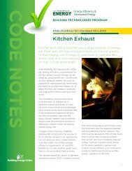
Commercial buildingControl requirements<strong>for</strong> All SystemsThermostatic controlof heating & coolingVentilationSupply fanmotor controlHeat pumpsupplemental heaterp. 13p. 13p. 19p. 17p. 22Humidity controlp. 34PrescriptivePath?NoPer<strong>for</strong>mance Pathp. 12YesSimple system?YesControl requirements<strong>for</strong> Simple Systemsp. 24NoPrescriptive requirements<strong>for</strong> Complex Systemsp. 28Prescriptive — An approach to satisfying the code requirements under which the design <strong>and</strong> constructionmust comply with the specific system <strong>and</strong> equipment parameters set <strong>for</strong>th in the code. This contrasts withthe per<strong>for</strong>mance approach to compliance, under which a certain amount of flexibility in those parameters isallowed, so long as the building utilizes less energy than a reference design.Simple system — A system that utilizes factory-assembled HVAC equipment, called packaged or unitaryequipment. In a simple system, one such unit is assigned to each zone. The exception to this is that the IECC alsoallows a heat-only system serving multiple zones to qualify as a simple system.Complex system — Also sometimes referred to as built-up, these systems include various components — chiller,cooling tower, boilers, pumps, fans, <strong>and</strong> more — that are assembled on site to <strong>for</strong>m the building HVAC system.Once assembled, the system may serve multiple zones with heating <strong>and</strong> cooling.How to Use this Guide 5
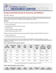
Control requirements<strong>for</strong> Simple SystemsEconomizersp. 24p. 24water loopdesigned <strong>for</strong> over300 kBtu/hr?YesHydronic systemsp. 27NoEndHydronic — Using water. A hydronic system is onethat circulates heated or chilled water through a loopto provide com<strong>for</strong>t in a zone or to provide the heatsource or sink <strong>for</strong> HVAC equipment.Zones — Portions of a building served with heating,cooling <strong>and</strong> ventilation. Zones have similar HVACrequirements <strong>and</strong> can there<strong>for</strong>e be served with asingle thermostat or set of sensors <strong>and</strong> a singlecontrol strategy.6 How to Use this Guide
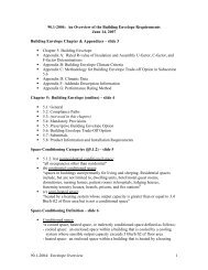
Prescriptive requirements<strong>for</strong> Complex Systemsp. 28EconomizersVAV fansHumidity controlp. 28p. 30p. 34Water loop(s)?NoYesHydronic systemsp. 35Water loopserves heat pump(s)or water-cooledA/C?NoYesHydronic heat pump<strong>and</strong> A/C systemsp. 40Fan speed control <strong>for</strong> heatrejection equipmentp. 42Multi-zone?YesMulti-zone systemsp. 44NoEndHow to Use this Guide 7
8 How to Use this Guide
Code Requirements <strong>and</strong>Compliance Checks
Per<strong>for</strong>mance PathMany building energy codes allow buildings to satisfy the code requirements either by meeting each specificrequirement or by demonstrating that the building per<strong>for</strong>ms as well or better than a reference buildingdesign that satisfies the specific requirements. Both ASHRAE 90.1 <strong>and</strong> the IECC offer a per<strong>for</strong>mance pathto compliance. However, even buildings following the per<strong>for</strong>mance path must meet some m<strong>and</strong>atoryrequirements relating to HVAC <strong>controls</strong>.Thermostatic control of heating <strong>and</strong> cooling <strong>and</strong> control of ventilation are required <strong>for</strong> all buildings; as aresome <strong>controls</strong> relating to supplemental heaters in heat pumps, humidity <strong>and</strong> commissioning. These nearlyuniversal requirements are discussed in the following section on control requirements <strong>for</strong> all systems. Latersections turn to requirements that may not be satisfied by buildings taking the per<strong>for</strong>mance path.10 Per<strong>for</strong>mance Path
Control Requirements <strong>for</strong> All SystemsThermostatic Control of Heating <strong>and</strong> CoolingThermostatic <strong>controls</strong> are required in each conditioned building zone. These devices must be capable ofsetting the zone’s target temperature <strong>for</strong> heating <strong>and</strong> cooling. They must also prevent simultaneous heating<strong>and</strong> cooling of the zone <strong>and</strong> allow <strong>for</strong> a range of allowable temperatures, known as a deadb<strong>and</strong>, in whichneither heating nor cooling is provided. Finally, the thermostatic <strong>controls</strong> must allow the system to scheduleunoccupied periods <strong>and</strong> occupied periods, allowing <strong>for</strong> a system start up period between. During theunoccupied period, heating <strong>and</strong> cooling target temperatures can be set back to conserve energy by allowing agreater range of space temperatures.Plan ReviewSuggested Compliance Check(s):• Check mechanical floor plans to verify that there is at least onethermostat per distinct occupancy area (figure 1).• Review the mechanical floor plans <strong>and</strong> mechanical schedule to locate control sequences <strong>and</strong> verifythat the design engineer has specified deadb<strong>and</strong>, set back <strong>and</strong> scheduling capabilities (figures 2-4).** If the building is equipped with a building automation system (BAS), then these capabilities will most likely beprovided by the BAS. The BAS specifications or manual should indicate that the required capabilities are present.Control Requirements <strong>for</strong> All Systems 11
Figure 1: Mechanical floor plan showing thermostats in multiple locationsFigure 2: Control diagram <strong>for</strong> variable air volume (VAV) box demonstrating 5 degree deadb<strong>and</strong>Zone Temperature Control Sequence• Heating set point (70°F), adjustable• Cooling set point (75°F), adjustable• Deadb<strong>and</strong> of 5°F shall be maintainedbetween heating <strong>and</strong> cooling set pointsAir Flow (%)100min70 75Zone Temperature (°F)Figure 3: Sample control sequence showing setback capabilitiesUnoccupied Mode:1. Air h<strong>and</strong>ling units <strong>and</strong> terminal units will go to unoccupied mode when room occupancy sensors <strong>and</strong>schedule program define the zone(s) served to be unoccupied.2. Zone temperature set point will reset to 55°F (heating mode) <strong>and</strong> 85°F (cooling mode).3. Outside air damper in closed position.12 Control Requirements <strong>for</strong> All Systems
Figure 4: Sample control sequence showing optimum start capabilitiesOptimum Start: The system shall calculate the time required to bring zones from the unoccupied temperature<strong>and</strong> humidity condition to occupied condition. This time shall be used to schedule the warm-up/cool-downperiod such that occupied conditions are achieved just prior to the scheduled occupied period.<strong>Building</strong> InspectionSuggested Compliance Check(s):• Verify that programmable thermostats <strong>and</strong> temperature <strong>and</strong> humidity sensors havebeen installed as shown in the approved mechanical plans (figure 5 <strong>and</strong> 7).• Confirm that the installed thermostats have deadb<strong>and</strong> <strong>and</strong> setback capabilities. Singlesetpoint thermostats with a heat/cool/auto setting do not comply (figure 6).Figure 5: Temperature sensor, as may be installed in a building with a building automation systemFigure 6: Programmable thermostat, as may be installed in building using packaged HVAC equipmentControl Requirements <strong>for</strong> All Systems 13
Figure 7: BAS screenshot showing temperature sensors measuring zone temperaturesAdditional Detail:a) ZoningEach zone is required to have a dedicated temperature control device. If the HVAC system is designed toregulate humidity, then each zone must also have a humidity control device.Code SectionsIECCASHRAE2009: 503.2.4.1 2007: 6.4.3.1.12012: 403.2.4.1 2010: 6.4.3.1.1b) Deadb<strong>and</strong>Temperature <strong>controls</strong> <strong>for</strong> each zone shall be capable of providing a range of 5 degrees above/belowsetpoint when no heating/cooling occurs. For example, a setpoint of 70°F <strong>for</strong> heating <strong>and</strong> 75°F <strong>for</strong> coolingprovides a 5 degree deadb<strong>and</strong> where no heating or cooling will occur.Code SectionsIECCASHRAE2009: 503.2.4.2 2007: 6.4.3.2, 6.4.3.1.22012: 403.2.4.2 2010: 6.4.3.2, 6.4.3.1.2c) Thermostatic setback capabilitiesSetback <strong>controls</strong> must be able to setback temperatures during unoccupied times to 55 <strong>for</strong> heating <strong>and</strong>85°F or 90°F <strong>for</strong> cooling.Code SectionsIECCASHRAE2009: 503.2.4.3.1 2007: 6.4.3.3.22012: 403.2.4.3.1 2010: 6.4.3.3.214 Control Requirements <strong>for</strong> All Systems
d) Automatic setback <strong>and</strong> shutdown capabilitiesProgrammable thermostats shall be capable of different programs <strong>for</strong> different daily occupancy schedules.They must also retain in<strong>for</strong>mation during power outage <strong>for</strong> 10 hours <strong>and</strong> have a temporary manualoverride option.Code SectionsIECCASHRAE2009: 503.2.4.3.2 2007: 6.4.3.3.12012: 403.2.4.3.2 2010: 6.4.3.3.1e) Optimum start <strong>controls</strong>The system <strong>controls</strong> shall be capable of varying the start time to bring each space up to setpointimmediately prior to scheduled occupancy. This optimum start capability recognizes that the system willrequire a variable amount of time to bring zones to com<strong>for</strong>table conditions, depending on the building’sunoccupied condition <strong>and</strong> the weather. Systems with a capacity less than 10,000 CFM may be exemptfrom this requirement.Code SectionsIECCASHRAE2009: NA 2007: 6.4.3.3.32012: 403.2.4.3.3 2010: 6.4.3.3.3f) Zone isolationWhere multiple zones are served by a common HVAC system, but will be occupied on different schedules,the system must include <strong>controls</strong> that allow the unoccupied zones to be automatically isolated. Whenisolated, the HVAC system will neither supply nor exhaust air from the unoccupied zones.Code SectionsIECCASHRAE2009: NA 2007: 6.4.3.3.42012: NA 2010: 6.4.3.3.4Supply Fan Motor ControlASHRAE 90.1-2010 introduced a new requirement <strong>for</strong> variable airflow <strong>controls</strong> in the following types ofequipment:• Air h<strong>and</strong>ling <strong>and</strong> fan coil units served by chilled water <strong>and</strong> having a supply fan motor larger than 5 hp.• Units serving a single zone <strong>and</strong> having direct expansion cooling capacity of more than 110,000 Btu/h.Such equipment is required to use two speed motors or variable-speed drives on the supply fan.Control Requirements <strong>for</strong> All Systems 15
Plan ReviewSuggested Compliance Check(s):• Review the fan schedule to see that large fans (5 hp <strong>and</strong> larger) arespecified with variable speed drives or two speed motors.Figure 8: Fan schedule indicating VSD to be providedFAN scheduleID Area Type Drive CFMT.S.P.(in H 2O)Basis ofDesignMax Wt.(lbs)Volt/PhElectricalHPControlPF-1 Stair UtilitysetPF-4 Elevator UtilitysetSF-1 Office VaneaxialRF-1 AHU-1 VaneaxialBelt 8000 0.5 400 480/3 7.5 VFDBelt 10000 0.5 400 480/3 7.5 VFDBelt 35000 200 480/3 40 VFDBelt 20000 200 480/3 25 VFD<strong>Building</strong> InspectionSuggested Compliance Check(s):• Verify that supply fans with motors greater or equal to 5 hp have been provided with VSDs (orother speed control devices) as indicated on the mechanical plans. Supply fans may be locatedon rooftops (simple systems) or mechanical rooms (complex systems) (figure 9). A buildingautomation system (BAS) may also show where equipment is controlled by a VSD (figure 10).16 Control Requirements <strong>for</strong> All Systems
Figure 9: VSD installed on a supply fanFigure 10: BAS screenshot indicating VSD control of supply fanCode SectionsIECCASHRAE2009: NA 2007: NA2012: NA 2010: 6.4.3.10VentilationThe basic requirement of <strong>controls</strong> relating to ventilation is that they be capable of reducing or shutting downventilation when it is not required. Many systems are required to have motorized supply air <strong>and</strong> exhaustdampers that automatically open when the zone served is scheduled to be occupied <strong>and</strong> close when the zoneis scheduled to be unoccupied. Systems with large ventilation requirements must also be capable of varyingthe amount of ventilation according with the real time needs of the zone.Control Requirements <strong>for</strong> All Systems 17
<strong>Plans</strong> ReviewSuggested Compliance Check(s):• If the building is taller than three stories <strong>and</strong> in climate zones 4 through 8,verify that motorized dampers are specified <strong>for</strong> outside air <strong>and</strong> exhaust/relief dampers on the mechanical floor plans or mechanical schedule.• Review the mechanical floor plans <strong>and</strong> mechanical schedule to locate control sequences<strong>and</strong> verify that the design engineer has defined a procedure whereby dampers willbe closed <strong>and</strong> fans will be shut off when zones are unoccupied (figure 11).• For large spaces (greater than 500 ft2), check the mechanical <strong>and</strong> electrical floorplans to see that CO 2or other sensors are specified <strong>and</strong> tied in to the <strong>controls</strong>ystem to enable dem<strong>and</strong> control ventilation (DCV) (figure 12).Figure 11: Sample control sequence showing damper controlOutside Air Damper Control: Outside air intake dampers shall open in response to a start signal. The dampersshall close <strong>and</strong> the fan shall stop in response to any of the following: stop signal, loss of control signal, loss ofelectrical power, or the AHU supply fan motor stops.Figure 12: Sample control sequence indicating DCVDem<strong>and</strong> Control of Ventilation: During occupied mode, zone requests <strong>for</strong> ventilation shall be determined basedon signals from zone-located CO2 sensors. A zone shall request ventilation when the CO2 concentration exceeds900ppm. In response to a request <strong>for</strong> ventilation, the system shall first increase the terminal unit airflow. Ifadditional ventilation is required, the system shall then increase the outdoor air rate at the air h<strong>and</strong>ler.<strong>Building</strong> InspectionSuggested Compliance Check(s):• Verify that outside air <strong>and</strong> exhaust/relief dampers have actuators that automatically open <strong>and</strong> close thedampers <strong>and</strong> that the dampers are in the closed position in spaces that are unoccupied (figure 13).• Verify that CO 2sensors included in the mechanical plans <strong>for</strong> the purpose of dem<strong>and</strong>control ventilation have been installed as shown in the plans (figure 14).• Review the mechanical plans <strong>and</strong> verify that automatic <strong>controls</strong> (i.e. occupancy sensor ormanual timers) have been provided <strong>for</strong> ventilation fans larger than 3/4 hp as shown.18 Control Requirements <strong>for</strong> All Systems
Figure 13: Motorized damperFigure 14: Top view of CO 2sensor (coin <strong>for</strong> scale)Additional Detail:a) DampersOutdoor air supply <strong>and</strong> exhaust/relief ducts shall have motorized dampers that automatically close whenthe spaces that they serve are not occupied. <strong>Building</strong>s less than three stories tall or in climate zones 1through 3 may use gravity dampers.Code SectionsIECCASHRAE2009: 503.2.4.4 2007: 6.4.3.4.3,6.4.3.4.1, 6.4.3.4.22012: 403.2.4.4 2010: 6.4.3.4.2, 6.4.3.4.1b) Ventilation fan <strong>controls</strong>Fans with motors greater or equal to three-quarter horsepower, must have <strong>controls</strong> that can shut off fanswhen not required. This control may be an occupancy sensor, timer, or other device.Code SectionsIECCASHRAE2009: NA 2007: 6.4.3.4.52012: NA 2010: 6.4.3.4.4Control Requirements <strong>for</strong> All Systems 19
c) Dem<strong>and</strong> control ventilationA control strategy that varies the minimum ventilation outdoor air based on occupancy is required <strong>for</strong>large, densely occupied spaces. This usually applies to spaces 500 square feet <strong>and</strong> larger that havean occupant load greater than or equal to 40 people per 1,000 square feet (IECC 2012 exp<strong>and</strong>ed theapplicability by reducing the threshold occupant load to 25 people per 1000 square feet). Typically,ventilation is controlled by varying the outdoor air intake based on the measured level of carbon dioxidewithin a space.Code SectionsIECCASHRAE2009: 503.2.5.1 2007: 6.4.3.92012: 403.2.5.1 2010: 6.4.3.9d) Heat recovery ventilation bypassIf a heat recovery ventilator (HRV) is installed, this HRV must not inhibit the operation of the economizer. Thiscan be accomplished through <strong>controls</strong> which allow the HRV to be bypassed when the economizer is working.Code SectionsIECCASHRAE2009: 503.2.6 2007: 6.5.6.12012: 403.2.6 2010: 6.5.6.1Heat Pump Supplemental HeaterIf the building has heat pumps with supplemental electric heaters, those supplemental heaters should notbe engaged until the heat pump’s heating capacity is exceeded. ASHRAE 90.1 exempts heat pumps that areregulated under the National Appliance Energy Conservation Act (those with a cooling capacity less than65,000 Btu/h) from this requirement.Plan ReviewSuggested Compliance Check(s):• Verify that the mechanical schedule or control sequence specifies that supplementalresistance heating cannot operate when the heat pump can meet the heating load. This maybe accomplished by specifying a multi-stage electronic thermostat programmed to initiatethe supplemental heater when the heat pump cannot meet the setpoint (figure 15).Figure 15: Sample heat pump control sequence showing auxiliary heat engaged as second stageMode Call <strong>for</strong> Action Signal to Heat Pump Delivered ActionHeat None H Reversing valve in heat positionStage 1 heat H, H1 Heat using compressorStage 2 heat H, H1, H2 Heat using compressor <strong>and</strong> auxiliary heater20 Control Requirements <strong>for</strong> All Systems
<strong>Building</strong> InspectionSuggested Compliance Check(s):• Check that the type of thermostat or building automation system specifiedin the approved mechanical submittal is installed <strong>and</strong> operating.Additional Detail:Code SectionsIECCASHRAE2009: 503.2.4.1.1 2007: 6.4.3.52012: 403.2.4.1.1 2010: 6.4.3.5Control Requirements <strong>for</strong> All Systems 21
Prescriptive Requirements <strong>for</strong> Simple SystemsEconomizersEconomizers are required in most buildings to allow the HVAC system to increase the amount of outsideair supplied to the zone if doing so will reduce energy consumption. This is possible, <strong>for</strong> example, when thezone is being cooled <strong>and</strong> the outside air is cool enough to meet part of that cooling dem<strong>and</strong>. Control of theeconomizer should allow it to vary the supply of outside air from the minimum required ventilation to 100percent outside air, based on the condition of the zone <strong>and</strong> the outside air. In simple systems, the economizeris likely to be integrated in packaged or unitary HVAC equipment. Thus, the economizer control strategy islikely to be found in the specifications <strong>for</strong> that equipment.Plan ReviewSuggested Compliance Check(s):• Check the mechanical schedule to verify that economizers are specified <strong>for</strong> systemsthat are larger than the thresholds shown in the table below (figure 16).IECC 2009 54,000 Btu/h in all climate zones except 1A, 1B, 2A, 7, <strong>and</strong> 8IECC 2012 33,000 Btu/h in all climate zones except 1A <strong>and</strong> 1BASHRAE 2007 65,000 Btu/h in climate zones 3B, 3C, 4B, 4C, 5B, 5C <strong>and</strong> 6B135,000 Btu/h in climate zones 2B, 5A, 6A, 7 <strong>and</strong> 8ASHRAE 2010 54,000 Btu/h in all climate zones except 1A <strong>and</strong> 1B• Locate control sequences <strong>and</strong> verify that the economizer <strong>controls</strong>equence meets the following requirements (figure 17):1) The supply of outside air varies from the minimum requirement to 100 percent.2) Economizers are sequenced with the mechanical cooling equipment <strong>and</strong> continue tofunction until the shut-off condition described in requirement 4, below, is reached.3) Economizers are not controlled only by mixed air temperature.22 Prescriptive Requirements <strong>for</strong> Simple Systems
4) The supply of outside air is reduced to the design minimumwhen one of the following conditions applies:• Outside air temperature exceeds:○○75°F in climate zones 1B, 2B, 3B, 3C, 4B, 4C, 5B, 5C, 6B, 7, or 8○○○○70°F in climate zones 5A, 6A, or 7A65°F in any other climate zone• The climate specific shut off condition is reached, as determined by anotherapproved approach from the code sections referenced in section c below.Figure 16: Economizer specified on mechanical scheduleAir H<strong>and</strong>ling UnitsSymbolLocation ServedAHU-11st Floor OfficesSupply Fan Type CentrifugalConfigurationFan CoilAir flow (CFM) 6,000Min air flow (CFM) 6,000Min outside air (CFM) 600HP: Motor 5Voltage/Phase 460/3ControlON/OFFIsolationInternalCooling Capacity Nominal Tons 15Total (MBH) 171Sensible (MBH) 137EDB (°F) 76EWB (°F) 63LDB (°F) 55LWB (°F) 54CW Flow (GPM) 30.0ENT Water Temp (°F) 44.0LVG Water Temp (°F) 56.0Heating Type NoneWeight LBS 3,000Unit Electrical MCA 8.3Voltage/Phase 460/3Basis of Design Manufacturer TraneModelT SeriesNotes 1NOTE: Provide with factory installed 0–100% economizer <strong>controls</strong> without barometric relief.Prescriptive Requirements <strong>for</strong> Simple Systems 23
Figure 17: Economizer control sequenceAHU — 1 & 2 Automatic Dampers• Outside Air Damper○○○○○○○○ModulatingClosed when AHU is not operating.Controlled by space temperature, time of day, outside air temperature, <strong>and</strong> ventilation requirementEconomizer cycle:◗◗Operates when outside air temperature is
) Control strategyEconomizers must not be controlled only by mixed air temperature <strong>and</strong> must be able to be sequencedwith mechanical cooling equipment. ASHRAE provides an exception <strong>for</strong> systems controlled from spacetemperature, such as single zone systems.Code SectionsIECCASHRAE2009: NA 2007: 6.5.1.1.22012: 403.1.1.2 2010: 6.5.1.1.2c) High limit shutoffWhen increase in outdoor air will no longer reduce cooling energy use, economizers must be able toreduce outdoor air to the design minimum.Code SectionsIECCASHRAE2009: NA 2007: 6.5.1.1.32012: 403.3.1.1.3 2010: 6.5.1.1.3Hydronic SystemsThe requirements <strong>for</strong> hydronic systems mainly apply to buildings with a complex, built up HVAC design.However, the IECC includes some control requirements <strong>for</strong> large (>300,000 Btu/h) systems that arecategorized as simple systems. One example of such a system is a boiler loop that supplies hot water <strong>for</strong>radiant heating in a large apartment building. Such simple, but large hydronic systems are required to complywith the applicable hydronic system <strong>controls</strong> that are discussed in the next section of this <strong>guide</strong>.Additional Detail:Code SectionsIECCASHRAE2009: 503.3.2 2007: NA2012: 403.3.2 2010: NAPrescriptive Requirements <strong>for</strong> Simple Systems 25
Control Requirements <strong>for</strong> Complex SystemsEconomizersThe requirements <strong>for</strong> economizers in complex systems are similar to those <strong>for</strong> simple systems. The economizermust vary the supply of outside air from the minimum required ventilation to 100 percent outside air, basedon the condition of the zone <strong>and</strong> the outside air. Despite this similarity, there are two reasons <strong>for</strong> providing aseparate discussion of economizers <strong>for</strong> complex systems. First, there is an additional requirement <strong>for</strong> complexsystems that the use of the economizer should not increase building heating. Second, the specification of theeconomizer in the design submittal is likely to look somewhat different <strong>and</strong> there<strong>for</strong>e the compliance checkwill be slightly different.Plan ReviewSuggested Compliance Check(s):• Check the mechanical schedule to verify that economizers are specified <strong>for</strong>systems that are larger than the thresholds shown in the table below.IECC 2009 54,000 Btu/h in all climate zones except 1A, 1B, 2A, 7, <strong>and</strong> 8IECC 2012 33,000 Btu/h in all climate zones except 1A <strong>and</strong> 1BASHRAE 2007 65,000 Btu/h in climate zones 3B, 3C, 4B, 4C, 5B, 5C <strong>and</strong> 6B135,000 Btu/h in climate zones 2B, 5A, 6A, 7 <strong>and</strong> 8ASHRAE 2010 54,000 Btu/h in all climate zones except 1A <strong>and</strong> 1B• Locate control sequences <strong>and</strong> verify that the economizer <strong>controls</strong>equence meets the following requirements (figure 19).*1) The supply of outside air varies from the minimum requirement to 100 percent.2) Economizers are sequenced with the mechanical cooling equipment.3) Economizers are not controlled only by mixed air temperature.26 Control Requirements <strong>for</strong> Complex Systems
4) The supply of outside air is reduced to the design minimumwhen one of the following conditions applies:• Outside air temperature exceeds:• 75°F in climate zones 1B, 2B, 3B, 3C, 4B, 4C, 5B, 5C, 6B, 7, or 8• 70°F in climate zones 5A, 6A, or 7A• 65°F in any other climate zone• The climate specific shut off condition is reached, as determined by anotherapproved approach from the code sections referenced in section c below.5) The economizer will reduce outside air to the minimum requirement when outsideair no longer provides cooling or when the system is in a heating mode.* If the building is equipped with a building automation system (BAS), then these capabilities will most likely beprovided by the BAS. The BAS specifications or manual should indicate that the required capabilities are present.Figure 19: Economizer control strategy shown in a control sequenceModulating Economizer• Controls position of a damper based on the Control State, Outside Air Temperature (OAT), <strong>and</strong> CoolingDem<strong>and</strong>.• Economizer available if:○○○○Cooling mode <strong>and</strong> fan onEcon. low limit temp SP < OAT < Econ. temp SP• When available, economizer:○○Locks out other cooling when Cooling Dem<strong>and</strong> < 25%○○Modulates from minimum to maximum position as Cooling Dem<strong>and</strong> increases from 0% to 25%<strong>Building</strong> InspectionSuggested Compliance Check(s):• Review the mechanical plans <strong>and</strong> verify that economizers have been providedon air h<strong>and</strong>lers as shown in the approved mechanical design.• Confirm that economizer operation is controlled as specified in the approvedmechanical design. This will often mean confirming that a building automationsystem has been installed <strong>and</strong> connected to the economizer.Control Requirements <strong>for</strong> Complex Systems 27
Additional Detail:a) Range of operationEconomizers shall be capable of operating at 100 percent outside air, even if additional mechanical cooling isrequired to meet the cooling load of the building. This strategy is known as integrated economizer control.Code SectionsIECCASHRAE2009: 503.4.1 2007: 6.5.1.32012: 403.4.1.1 2010: 6.5.1.3b) System integrationEconomizers should be used <strong>for</strong> cooling, even if supplemental mechanical cooling is required.Code SectionsIECCASHRAE2009: NA 2007: 6.5.1.32012: 403.4.1.3 2010: 6.5.1.3c) High limit shutoffWhen increase in outdoor air will no longer reduce cooling energy use, economizers must be able toreduce outdoor air to the design minimum.Code SectionsIECCASHRAE2009: NA 2007: 6.5.1.1.32012: NA 2010: 6.5.1.1.3d) Heating impactUse of the economizer must not result in an increased use of building heat.Code SectionsIECCASHRAE2009: NA 2007: 6.5.1.42012: 403.4.1.4 2010: 6.5.1.4Variable Air Volume (VAV) FansVAV fans with motors larger than 10 hp (7.5 hp under IECC 2012), must be driven by variable speed drives,use vane-axial fans with variable-pitch blades, or incorporate <strong>controls</strong> such that motors use at most 30%of the design fan power when the system delivers 50% of the design air volume. The most common meansof meeting this provision is with a variable speed drive controlled by a static pressure sensor located in thesupply air duct. The pressure measured by the sensor is used to set the speed of the drive, <strong>and</strong> the sensor28 Control Requirements <strong>for</strong> Complex Systems
must be positioned well down the duct from the fan to provide good feedback. As heating or cooling dem<strong>and</strong>decreases in the zones served, the dampers that control the supply of conditioned air to those zones willbegin to close. As they close, the pressure in the duct increases. The sensor measures this increase <strong>and</strong> signalsthe drive to slow until the static pressure setpoint is achieved.When the zone dampers are controlled by digital <strong>controls</strong>, the system efficiency should be further increasedby resetting the static pressure setpoint pressure lower, until the damper serving the zone with the greatestdem<strong>and</strong> is almost fully open. The control of VAV fans through this method is an important <strong>and</strong> somewhatcomplicated part of the HVAC control design strategy. However, verifying compliance with the coderequirements requires only a few steps.Plan ReviewSuggested Compliance Check(s):• Check the mechanical floor plan <strong>and</strong> mechanical schedule to see that large VAV fans arespecified with VSDs or are vane-axial fans with variable-pitch blades (figure 20).• If a direct digital control (DDC) system is specified on the plans, then locate <strong>controls</strong>equences <strong>and</strong> verify that the design engineer has defined a pressure reset strategy.In the strategy, the speed of the drive, often stated as a percentage, should be relatedto the operation of a remotely located zone box or “terminal unit” (figure 21).*• Check the mechanical <strong>and</strong> electrical floor plans to verify that a pressure sensor is specifiedto be located in the supply air duct, well away from the supply fan (figure 22).* If the building is equipped with a building automation system (BAS), then these capabilities will most likely beprovided by the BAS. The BAS specifications or manual should indicate that the required capabilities are present.Figure 20: VSD specified on mechanical scheduleRemarks• Split system HVAC unit, suspended air h<strong>and</strong>ler, max height 48”• Hot water heating coil with 2-way control valve sized <strong>for</strong> coil per<strong>for</strong>mance• Variable frequency drive supply fan with variable air volume pressure control• 100% outdoor air integrated economizer with differential dry bulb control• Air flow meter• Factory installed DDC <strong>controls</strong> with selectable protocol• Remote <strong>controls</strong> interface• Premium efficiency motors• Low leakage dampersControl Requirements <strong>for</strong> Complex Systems 29
Figure 21: Pressure reset strategy shown in control sequenceSupply Fan Control via Static Pressure Control: Controller shall modulate supply fan VFD speed to maintainstatic pressure setpoint.• Initial static pressure setpoint shall be 0.75in H 2O.• AHU controllers shall be networked with their associated terminal units.• The static pressure setpoint shall be reset lower, until all airflow requests are satisfied <strong>and</strong> the damper onone terminal unit is wide open.• The DDC controller shall modulate fan speed to maintain the duct static pressure setpoint. As duct pressuredecreases, fan speed will increase. As duct pressure increases, fan speed will decrease.Figure 22: Illustration of VSD (here VFD) control based on static pressure sensor <strong>and</strong> zone dampers<strong>Building</strong> InspectionSuggested Compliance Check(s):• Verify that VSDs (or variable pitch vane-axial fans) have beeninstalled as shown in the approved mechanical design.• Confirm that static pressure sensor(s) have been installed as shown in the approved mechanical design.• If the control sequence in the approved submittal included static pressurereset, check that the corresponding control system (most likely a buildingautomation system) is installed <strong>and</strong> operational (figure 23).30 Control Requirements <strong>for</strong> Complex Systems
Figure 23: BAS screen shot indicating control of VSD controlling supply fan based on static pressureAdditional Detail:a) VAV fan controlIndividual VAV fans greater than or equal to 10 horsepower in size must have a VSD, a vane-axial fan withvariable-pitch blades, or other means to control airflow that use 30% or less of the design fan power todeliver 50% of the design airflow. Systems with digital control <strong>for</strong> individual zones must reset the drivespeed to meet the need of the zone requiring the highest supply fan pressure. The IECC 2012 exp<strong>and</strong>edthe applicability by reducing the threshold fan size to 7.5 horsepower.Code SectionsIECCASHRAE2009: 503.4.2 2007: 6.5.3.2.12012: 403.4.2 2010: 6.5.3.2.1b) Static pressure sensor locationWhere static pressure sensors are used to control VAV fans, they must be positioned so that the pressuresetpoint based on the sensor is no more than one-third the total design static pressure of the supply fan.Typically, this means the sensor must be positioned closer to the farthest zone supplied than to the fan.Each major duct branch should have at least one sensor.Code SectionsIECCASHRAE2009: NA 2007: 6.5.3.2.22012: 403.4.2.1 2010: 6.5.3.2.2Control Requirements <strong>for</strong> Complex Systems 31
c) VAV fan pressure reset strategyIf direct digital control of individual zone boxes reports to central control panel, then a static pressurereset strategy must be included in the <strong>controls</strong>. Reset must to be based on the zone requiring thehighest supply pressure.Code SectionsIECCASHRAE2009: 503.4.2 2007: 6.5.3.2.32012: 403.4.2.2 2010: 6.5.3.2.3Humidity ControlWhere humidifiers or dehumidifiers are provided, the system must control their operation to preventsimultaneous humidification <strong>and</strong> dehumidification <strong>and</strong> to shut off the components when they are not required.Plan ReviewSuggested Compliance Check(s):• If the system has a humidifier with a preheat jacket, then confirm on the mechanical floorplan that a valve is shown on the hot water supply line feeding the preheat jacket.• Verify that control of the preheat valve is described as a note oneither the mechanical schedule or mechanical plans.*• Verify that the control sequence specifies a means to preventsimultaneous humidification <strong>and</strong> dehumidification.** If the building is equipped with a building automation system (BAS), then these capabilities will most likely beprovided by the BAS. The BAS specifications or manual should indicate that the required capabilities are present.<strong>Building</strong> InspectionSuggested Compliance Check(s):• Where applicable, verify that an automatic valve has been installed on humidifier preheat jackets.• Verify that simultaneous humidification <strong>and</strong> dehumidification has been prevented inaccordance with the approach defined in the approved mechanical design.Additional Detail:a) Humidifier shutoffHumidifiers with preheating jackets mounted in the airstream shall be provided with an automatic valve toshut off preheat when humidification is not required.32 Control Requirements <strong>for</strong> Complex Systems
Code SectionsIECCASHRAE2009: NA 2007: 6.4.3.62010: 6.4.3.6 2012: NAb) Simultaneous humidification/dehumidificationLimit switches, mechanical stops, or other means of control, such as a sequence of operations, must beincluded that are capable of preventing simultaneous humidification <strong>and</strong> dehumidification.Code SectionsIECCASHRAE2009: NA 2007: 6.4.3.72012: NA 2010: 6.4.3.7Hydronic SystemsHVAC systems often operate at peak capacity <strong>for</strong> only a small portion of the heating <strong>and</strong> cooling season.Energy codes require that hydronic systems be provided with <strong>controls</strong> to reduce the system’s energyconsumption when operating at less than peak capacity. This is achieved through equipment sequencing,reducing the pumping of fluid through the system, <strong>and</strong> by resetting the temperature of the hot water <strong>and</strong>chilled water supply.Plan ReviewSuggested Compliance Check(s):• Review the boiler specifications in the mechanical schedule to verify that largeboilers are required to have multistaged or modulating burners.• If multiple boilers are specified, check the control specifications to confirmthat they will be linked to a common control system (figure 24).*• For large systems (see additional details below), check mechanical schedules to verify thatVSDs or multi-staged pumps are provided <strong>for</strong> the pumps. Differential pressure sensorsshould also be specified, to provide the necessary feedback to the <strong>controls</strong> (figure 25).• Review control sequences to ensure that a supply water temperature reset is included (figure 26).*• For heated <strong>and</strong> chilled water systems with one shared distribution network (a 2-pipesystem), review control sequences to verify that the system does not switch betweenheating <strong>and</strong> cooling without an outside air temperature change of at least 15 degrees<strong>and</strong> that <strong>controls</strong> can prevent such a switch without a 4 hour interval (figure 27).*• Verify that language is included in control sequences <strong>for</strong> boilers <strong>and</strong> chillers toreduce flow through the plant when capacity is reduced (figure 28).*Control Requirements <strong>for</strong> Complex Systems 33
* If the building is equipped with a building automation system (BAS), then these capabilities will most likely beprovided by the BAS. The BAS specifications or manual should indicate that the required capabilities are present.Figure 24: Sample control sequence indicating that boilers are sequenced <strong>and</strong> modulateHot Water Pump Operation:• Pumps operate in lead/lag fashion.• Upon initiation of system operation, start lead pump.• Lead pump VFD speed modulates to maintain heating water system differential pressure setpoint(20 psid, adjustable).• During low load condition, flow is maintained through lead boiler at all times.• Isolation valve on st<strong>and</strong>by boiler is closed when st<strong>and</strong>by boiler is off.Figure 25: Sample boiler pump sequence of operations demonstrating variable flow capabilities/VSDBoiler Sequencing:• When flow is sensed from A to B in the crossover line, the DDC shall start primary boiler <strong>and</strong> hot water pump.• Manufacturer <strong>controls</strong> will modulate the burner valve to maintain boiler hot water temperature.• When load increases to the point that flow is again sensed from A to B in the crossover line, the DDC shall startst<strong>and</strong>by boiler.• As load decreases, the DDC shall stage boilers off in reverse order.Figure 26: Sample control sequence indicating supply water temperature is resetChilled Water Setpoint (CHWST) Reset• The default CHWST is 44°F.• When the speeds of pumps on the secondary loop are at the minimum, start CHWST reset.• CHWST will be reset proportionally between 48°F <strong>and</strong> 42°F:○○48°F; all cooling coil valves are less than 90% open.○○42°F; 3+ cooling coil valves are more than 90% open.• Continue CHWST reset until the speed of one or more pumps on the secondary loop exceeds the minimum.34 Control Requirements <strong>for</strong> Complex Systems
Figure 27: Illustrated control sequence <strong>for</strong> two pipe changeoverFigure 28: Sample control sequence <strong>for</strong> pump isolationChilled Water Pump Sequencing:• In Cooling Mode, DDC shall start one system pump which shall run continuously.• System pump variable speed drive will modulate to maintain the differential pressure setpoint (20 psid,adjustable).• Second system pump will start if the differential pressure falls below the setpoint.• When both pumps operate, they shall modulate at the same speed to achieve the differential pressure setpoint.• When the system flow falls to 50% of design flow, the second pump shall turn off.<strong>Building</strong> InspectionSuggested Compliance Check(s):• Confirm that multiple boilers are connected to a common control system, such asa building automation system, <strong>and</strong> that boilers with greater than 500,000 btu/hcapacity are equipped with multistage or modulating boilers (figure 29).• Confirm that pump speed <strong>controls</strong> (e.g. variable speed drive or multiple-staged pumps) shownin the approved mechanical design have been installed on all pumps (figure 30).• Verify that temperature sensors have been installed on chilled water supply, chilledwater return, hot water supply <strong>and</strong> hot water return pipes (figure 31).• Verify that the approved approach <strong>for</strong> controlling supply water temperature reset,typically a building automation system, is installed <strong>and</strong> operational (figure 31).Control Requirements <strong>for</strong> Complex Systems 35
Figure 29: Linked boiler controllersFigure 30: Multiple pumps with flow controlFigure 31: BAS showing temperature sensors on supply <strong>and</strong> return pipingAdditional Detail:a) Boiler sequencingHeating systems made up of multiple boilers must be able to be sequenced, such that boilers can beautomatically shut off as they are no longer needed to meet the heating requirement. Similarly, systemswith one large boiler (greater than 500,000 btu/h input capacity) must have a burner that is eithermultistaged or modulating.36 Control Requirements <strong>for</strong> Complex Systems
Code SectionsIECCASHRAE2009: 503.4.3 2007: NA2012: 403.4.3 2010: NAb) Variable flowBoth IECC <strong>and</strong> ASHRAE require <strong>controls</strong> capable of reducing pump flow in large hydronic systems by atleast 50% using VSDs or multi-stage pumps when the system is operating under part load conditions.However, the threshold of application differs. IECC requires such <strong>controls</strong> <strong>for</strong> systems with capacity greateror equal to 300,000 Btu/h. ASHRAE requires the <strong>controls</strong> <strong>for</strong> systems with individual pump motors largerthan 5 horsepower or total pump system power greater than 10 horsepower.Code SectionsIECCASHRAE2009: 503.4.3.4(2) 2007: 6.5.4.12012: 403.4.3.4(2)2010: 6.5.4.1c) Supply water temperature resetSystems with a design heating or cooling capacity greater than 300,000 Btu/h must include <strong>controls</strong>capable of resetting the supply water temperature according to the heating or cooling dem<strong>and</strong>. The returnwater temperature or outside air temperature may serve as indicators of this dem<strong>and</strong>. ASHRAE providesan exception <strong>for</strong> variable flow systems.Code SectionsIECCASHRAE2009: 503.4.3.4 2007: 6.5.4.32012: 403.4.3.4 2010: 6.5.4.3d) Two-pipe changeoverSystems that provide heated <strong>and</strong> chilled water to zones using a single supply <strong>and</strong> return loop must have<strong>controls</strong> that prevent the initiation of heating within four hours of cooling, or the reverse. In addition,the change from heating to cooling, or the reverse, should be separated by a difference in outside airtemperature of at least 15 degrees. The heated <strong>and</strong> chilled water supply temperatures at changeovershould be less than 30°F apart.Code SectionsIECCASHRAE2009: 503.4.3.2 2007: 6.5.2.2.22012: 403.4.3.2 2010: 6.5.2.2.2Control Requirements <strong>for</strong> Complex Systems 37
e) Pump isolationChilled water <strong>and</strong> boiler plants with multiple chillers or boilers must be able to reduce flow through systemwhen a chiller or boiler is turned off.Code SectionsIECCASHRAE2009: 503.4.3.5 2007: 6.5.4.22012: 403.4.3.5 2010: 6.5.4.2Hydronic Heat Pump <strong>and</strong> Unitary Air Conditioning SystemsSystems that employ a water loop to provide a source or sink of heat <strong>for</strong> heat pumps or unitary air conditionersare required to have <strong>controls</strong> to vary the flow of water through the system as a function of dem<strong>and</strong>.Plan ReviewSuggested Compliance Check(s):• Review the piping diagram to verify that two position valves are shown on the water loop ofhydronic heat pumps <strong>and</strong> water-cooled air conditioners that can shut off circulation of waterto the compressor of each individual heat pump or air conditioning unit (figure 32).• Verify that the control sequences allow a water supply temperature deadb<strong>and</strong> of 20°Fbetween initiation of heat rejection <strong>and</strong> heat addition on the water loop.*• Review the mechanical plans to verify that when the system is not in cooling mode circulationof water to the tower will be prevented by an automatic valve or a controlled pump, or thatpositive closure dampers are provided to stop air circulation through a closed circuit tower.• Check mechanical schedule or control sequences to verify that the pumps servinghydronic heat pump water loops have been provided with VSDs.* If the building is equipped with a building automation system (BAS), then these capabilities will most likely beprovided by the BAS. The BAS specifications or manual should indicate that the required capabilities are present.Figure 32: Illustration of heat pump piping showing location of two position valves38 Control Requirements <strong>for</strong> Complex Systems
<strong>Building</strong> InspectionSuggested Compliance Check(s):• Verify that two position valves have been installed on hydronic heat pumps <strong>and</strong> water cooledair conditioners, as shown on the approved mechanical piping diagram (figure 33).• Verify that the pumps serving hydronic heat pump water loops have beenprovided with VSDs, where shown on the approved mechanical plans.• Verify that heat loss through cooling towers is controlled using automatic valves, pumps,or positive closure dampers, as shown in the approved mechanical design.Figure 33: Two position (open/close) valve with electric actuatorAdditional Detail:a) Two-position valveIECC 2012 requires two position valves on hydronic heat pumps where the total hydronic system pumppower is greater than 10 hp.ASHRAE requires two position valves on hydronic heat pumps <strong>and</strong> water cooled air conditioners. ASHRAE2007 provides an exception when total hydronic system pump power is less than 5 hp.Code SectionsIECCASHRAE2009: NA 2007: 6.5.4.4.12012: 403.4.3.3.3 2010: 6.5.4.4.1b) Deadb<strong>and</strong>Hydronic heat pump water loops shall have <strong>controls</strong> that can provide a water supply temperature deadb<strong>and</strong>of at least 20 degrees F between initiation of heat rejection (cooling tower) <strong>and</strong> heat addition (boiler).Code SectionsIECCASHRAE2009: 503.4.3.3.1 2007: 6.5.2.2.3(a)2012: 403.4.3.3.1 2010: 6.5.2.2.3(a)Control Requirements <strong>for</strong> Complex Systems 39
Figure 34: Mechanical schedule showing cooling tower fans equipped with VSDCOOLING TOWERSymbolLocation ServedCT-1ChillerHeat Rejection Tons 800Type Cells 1DischargeVerticalFluid EWT (°F) 90LWT (°F) 77Flow (GPM) 1,500Ambient (°F) 67Nozzle (ft WG) 4FluidWaterFan Type AxialNumber 1Air flow (CFM) 170,000Motor HP 25ControlVFDVoltage/Phase 460/3Basin Heater Number 1Capacity 12Voltage/Phase 460/3Pipe Connections Supply (in) 10Return (in) 14Make-up (in) 2Drain (in)1 ½Overflow (in) 3Weight LBS 31,000Basis of Design Manufacturer ABC IncModelModel XYZNotesFigure 35: Sample note on mechanical scheduleNOTE: Cooling tower fan VFD modulates speed to maintain condensing water temperature setpoint.Control Requirements <strong>for</strong> Complex Systems 41
<strong>Building</strong> InspectionSuggested Compliance Check(s):• Verify that fans 7.5 hp <strong>and</strong> greater have been provided with devices<strong>for</strong> fan speed control (e.g. VSD) (figure 36).• Confirm that the means of controlling fan speed identified in the approved mechanicaldesign, typically a building automation system, has been installed <strong>and</strong> is operational.Figure 36: Cooling tower motor — check <strong>for</strong> connection to VSDAdditional Detail:Code SectionsIECCASHRAE2009: 503.4.4 2007: 6.5.5.22012: 403.4.4 2010: 6.5.5.2Multi-zone SystemsLarge buildings typically have HVAC systems that can heat, cool, reheat, <strong>and</strong> recool air moving to multiplezones at the same time. Multiple-zone systems must have VAV <strong>controls</strong> capable of reducing the supply air toany zone be<strong>for</strong>e reheating, recooling, or mixing warm <strong>and</strong> cool air streams. IECC 2012 requires the supply airto be reduced to 30% of maximum, to 300 CFM, or to the level required <strong>for</strong> minimum ventilation be<strong>for</strong>e anyreheating, recooling or mixing. The requirements of ASHRAE are similar, though systems shown to reduceannual energy use by providing more supply air are allowed. ASHRAE 2010 also introduces a method <strong>for</strong>systems with digital control of zone boxes to control the outdoor air intake based on the “zone ventilationefficiency” — the efficiency at which the system delivers outside air to the breathing zone.Plan ReviewSuggested Compliance Check(s):• Verify that control sequences include language <strong>for</strong> VAV system optimization(i.e. indicate that supply air is reduced prior to reheating/recooling):• Single duct VAV systems should reduce supply air be<strong>for</strong>e reheating/recooling takes place42 Control Requirements <strong>for</strong> Complex Systems
• Dual duct VAV systems should minimize the amount of hot/cold air mixing by reducing flow (figure 37)• Verify that language <strong>for</strong> supply air temperature reset is included in control sequences (figure 38)Figure 37: Sample control sequence <strong>for</strong> dual duct VAV systemOccupied Mode• Cooling○○Full cooling: Cold deck air damper opens to the maximum position.○○As cooling load decreases, cold deck air damper modulates more closed.○○No call <strong>for</strong> cooling: Cold deck air damper closes to the minimum position.• Heating○○Full heating: Hot deck air damper opens to the maximum position.○○As heating load decreases, hot deck air damper modulates more closed.○○No call <strong>for</strong> heating: Hot deck air damper closes to the minimum position.Control Requirements <strong>for</strong> Complex Systems 43
Figure 38: Sample control sequence <strong>for</strong> supply air temperature resetSupply Air Temperature ResetWhen occupied, the supply air temperature(SAT) is reset from 53°F to 65°F using thefollowing logic:• When the outside air temperature (OAT) is70°F <strong>and</strong> above, SAT shall be 53°F.• When OAT is 65°F to 70°F, the SAT isreset based on system dem<strong>and</strong> betweenminimum <strong>and</strong> maximum values that varylinearly with temperature (see figure).• When OAT is below 65°F, reset SATbetween 55°F <strong>and</strong> 65°F based on systemdem<strong>and</strong>.• System dem<strong>and</strong> is determined using a trim<strong>and</strong> respond logic:○○When the fan is off, SAT is at 65°F○○When the fan is on, every 2 minutes:◗◗◗◗Increase the SAT setpoint by 0.2°F if there are no zone cooling requests*If there are more than two cooling requests, decrease the setpoint by 0.3°F* cooling requests are generated when the cooling loop of any zone served is >99%Source: EnergyDesignResources, Advanced Variable Air Volume System Design Guide, March 2007SAT Setpopint65°F55°F53°F65°F 70°FOAT<strong>Building</strong> InspectionSuggested Compliance Check(s):• Confirm that the building automation system specified in the approved design is installed <strong>and</strong> operational.• Checking that multi-zone VAV systems are optimized is an intensive procedure, wellbeyond the scope of building inspection. However, ASHRAE 90.1-2010 <strong>and</strong> IECC 2012require commissioning to be per<strong>for</strong>med on many commercial buildings. The commissioningprovider’s report should describe how the system was tested <strong>and</strong> optimized.Additional Details:a) Multi zone VAV system optimization controlSystems with digital control of zone boxes must automatically adjust supply air in response to changesin system ventilation efficiency. This approach allows outside air supply to be provided at below designrates, so long as the zone that is least effective in delivering outside air to the breathing zone maintainsacceptable indoor air quality. Detailed guidance on this approach is provided in ASHRAE St<strong>and</strong>ard 62.1.44 Control Requirements <strong>for</strong> Complex Systems
Code SectionsIECCASHRAE2009: NA 2007: NA2012: NA 2010: 6.5.3.3b) Single duct VAV systemsTerminal Units shall reduce supply of supply air to 30% of maximum, to 300 CFM, or to a level sufficient toprovide the minimum required ventilation be<strong>for</strong>e reheating/recooling.Code SectionsIECCASHRAE2009: 503.4.5.1 2007: - 6.5.2.12012: 403.4.5.1 2010: 6.5.2.1c) Dual duct VAV systemsDual duct systems shall have terminal units that can minimize flow from one duct to 30% of maximum, to 300CFM, or to a level sufficient to provide the minimum required ventilation prior to mixing from second duct.Code SectionsIECCASHRAE2009: 503.4.5.2 2007: 6.5.2,12012: 403.4.5.2 2010: 6.5.2.1d) Supply air temperature resetSupply air temperature (SAT) reset is required <strong>for</strong> multi zone HVAC systems. SAT must be reset in responseto building load or outside air temperature. The <strong>controls</strong> must allow SAT reset that is at least 25 percent ofthe difference between the design SAT <strong>and</strong> room air temperature.Code SectionsIECCASHRAE2009: 503.4.5.4 2007: NA2012: 403.4.5.4 2010: 6.5.3.4
<strong>Building</strong> Technology ProgramThe U.S. Department of Energy’s <strong>Building</strong> EnergyCodes Program is an in<strong>for</strong>mation resource onnational model energy codes. We work with othergovernment agencies, state <strong>and</strong> local jurisdictions,national code organizations, <strong>and</strong> industry topromote stronger building energy codes <strong>and</strong> helpstates adopt, implement, <strong>and</strong> en<strong>for</strong>ce those codes.BECP Websitewww.energycodes.govBECP Technical Supporttechsupport@becp.govwww.energycodes.gov/support/helpdesk.phpEERE In<strong>for</strong>mation Center1-877-EERE-INFO (1-877-337-3463)www.eere.energy.gov/in<strong>for</strong>mationcenterPNNL-83271 • September 2011Printed with a renewable-source ink on paper containing at least50% wastepaper, including 10% post-consumer waste.