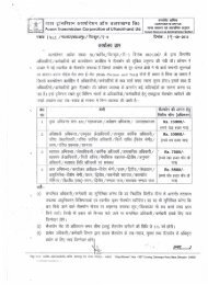
NOT FOR SALE / FOR WEB BASED TENDERING ONLY POWER ...
NOT FOR SALE / FOR WEB BASED TENDERING ONLY POWER ...
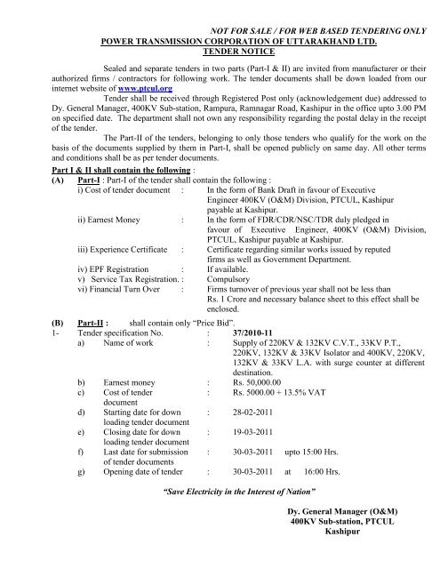
NOT FOR SALE / FOR WEB BASED TENDERING ONLY POWER ...

Create successful ePaper yourself
Turn your PDF publications into a flip-book with our unique Google optimized e-Paper software.
<strong>NOT</strong> <strong>FOR</strong> <strong>SALE</strong> / <strong>FOR</strong> <strong>WEB</strong> <strong>BASED</strong> <strong>TENDERING</strong> <strong>ONLY</strong>TENDER <strong>FOR</strong>MTENDER <strong>FOR</strong> ………………………………………………………………………………………..................................................................................................................................................against Tender Specification No. ………………………………From,To,Dy. General Manager (O&M)PTCUL400KV Sub-station, Ramnagar RoadKashipurSir,With reference to your invitation to tender for the above, I hereby offer to the Power Trans. Corp. ofUttarakhand Ltd. items in the schedule of prices and delivery annexed or such portion thereof, as youdetermine in strict accordance with the annex condition of contract form "B" specification and schedule ofrates to the satisfaction of the purchaser or in default thereof to forfeited and pay to Power Trans. Corp. ofUttarakhand Ltd. the sum of earnest money mentioned in the said condition.The rates quoted are inclusive pro-rate and in full of satisfaction of the all claims.I/We agree to abide by this tender for the period of 120 days from the date fixed for receiving thesameA sum of Rs. .................................... in the form of ................................................. is........................... herewith forwarded duly endorsed in favour of Executive Engineer, 400KV (O&M)Division, Kashipur as earnest money deposit, the full value of which shall be retained by the PowerTransmission Corporation of Uttarakhand Ltd. on account of security deposit specified in clause-3 of thesaid conditions of form "A".SignedDated the day of 20Yours faithfullySIGNATURE OF THETENDERER IN FULLWitnessAddressOccupation
TENDER PER<strong>FOR</strong>MA<strong>NOT</strong> <strong>FOR</strong> <strong>SALE</strong> / <strong>FOR</strong> <strong>WEB</strong> <strong>BASED</strong> <strong>TENDERING</strong> <strong>ONLY</strong>SCHEDULE 'C'Sr.Particulars1. Specification No. against which you have tendered.2. Receipt No. & date by which cost of the TenderSpecification deposited by you.3. Specification of the material / work for which tenderhas been submitted. Are you a manufacturer /working contractor of the item / work ordered for orace-credited Agent of manufacture?4. Quantity offered (In there are two or more itemsstate quantities separately with units.)5. Amount of form in which earnest money depositedwith Executive Engineer, 400KV (O&M) Division,Kashipur Please give referenda in this connection.6. Do you agree to all the conditions of the Tenderspecification clearly which you would desire in thegeneral conditions of contract form (It may pleasebe noted that it shall be entirely at the discretion ofthe purchaser to accept or to reject the modificationproposed.)7. Please state clearly(Answer Yes or No) if you wouldagree to undertake / execute the supply / worksincase the modification as suggested under Sl. 6 isnot acceptable to the Corp. without imposing anyfurther condition(s) from your side.8. Give the reference who can certify your financialstatus & capability to undertake such supply order /tender. One of the references should be scheduleBank of India.9. Do you confirm that there are no typographicalerrors/omissions in your tender and all otherdocuments forming part of the Tender? (Yes/No).10. Have you submitted list of past suppliers workexecuted.11. What is the validity period of your Tender?
<strong>NOT</strong> <strong>FOR</strong> <strong>SALE</strong> / <strong>FOR</strong> <strong>WEB</strong> <strong>BASED</strong> <strong>TENDERING</strong> <strong>ONLY</strong>12. What is the Delivery / Completion Period? Pleasestate if the delivery is guaranteed under penaltystate the delivery date/month.13. Are you agreeable to the delivery period beingreckoned from the date of receipt of acceptanceletter by you?PRICE/PRICES1. Is the quoted prices for each item FIRM/Firm in allrespect?2. If the quoted price(s) is variable please give theprice variation formula and also the basis (withdocuments) of quoted price.(A) Do you agree that the price variation clauses shallbe applicable only within the guaranteed completionperiod as mentioned in tender and shall not beapplicable there after even if extension in delivery isgranted at later stage on any ground whatsoever.(B) Have you furnished the documentary evidence inrespect of basis mentioned in item 2(A) above?3. Is the quoted price exclusive of Trade Tax / SalesTax / Service Tax?4. If the price is inclusive of Trade Tax / Sale Tax /Service Tax. What is the amount of Trade Tax /Sale Tax / Service Tax included and at what rate?5. Is the quoted price exclusive of Excise Duty onfinished product?6. If the quoted price is inclusive of Excise Dutyincluded and at what rate?7. If the quoted price exclusive of transit Insurancecharges covering 30 days?8. If the quoted prices are inclusive of insurance thenmention the amount of insurance charges includedand its rate?9. Please state if you would claim any other chargesover & above the price as extra which are notcovered by Sl. No. .................... to............................. If yes, please state extraseparately indicating the amount in rupees againsteach on per unit basis.
<strong>NOT</strong> <strong>FOR</strong> <strong>SALE</strong> / <strong>FOR</strong> <strong>WEB</strong> <strong>BASED</strong> <strong>TENDERING</strong> <strong>ONLY</strong>10. Do you offer any discount and if so what is thediscount in unit.11. Have you read the standard clause 2.10 of specialconditions which for change of price/prices orits/their structure after the opening of tender?TECHNICAL SPECIFICATION:-(For Supply Only)1. Is the material offered according to the specificationof the purchaser?2. If the material offer is/not exactly accordingly to thepurchasers specification. Please get the verificationfrom the same.3. Have you enclosed leaflets, descriptive andillustrative catalogues in triplicate?4. Have you enclosed copies of test certificates inrespect of material offered?5. Have you submitted sealed sample (Nonrefundable) and delivered the same to the office ofE.E., 400KV (O&M) Division, Kashipur.6. Have you filled up the schedule of technicalparticulars?7. Guarantee of offered material shall be 6 or 12months.ADDRESSPlace:Date:
<strong>NOT</strong> <strong>FOR</strong> <strong>SALE</strong> / <strong>FOR</strong> <strong>WEB</strong> <strong>BASED</strong> <strong>TENDERING</strong> <strong>ONLY</strong>DEPARTURE FROM SPECIFICATIONSCHEDULE "B"Sl.No. Name of Items Description of Reference of ClauseDeparturein Specifications
<strong>NOT</strong> <strong>FOR</strong> <strong>SALE</strong> / <strong>FOR</strong> <strong>WEB</strong> <strong>BASED</strong> <strong>TENDERING</strong> <strong>ONLY</strong>APPLICATION FROM TENDERER(On a Non-judicial stamp paper of Rs.5/- plus 0.20 paise revenue stamp affixed)AGREEMENTTender invited by ....................................................Tender for ....................................................Tender Notice No. ....................................................and Date ....................................................Name of Tenderer ....................................................In consideration of the Power Transmission Corporation of Uttarakhand Ltd. havingtreated the tenderer to be an eligible person, whose tender maybe considered, the tendered, thetenderer here-by agrees to the condition that the proposal in response to the above invitation shallnot be withdrawn within three months from the date of opening of the tender and also to thecondition that if there, after the tenderer withdraws his proposal within the said period, the Earnestmoney deposited by him may be forfeited to the Power Transmission Corporation of UttarakhandLtd. on the discretion of the Engineer-in-charge.Signed this ........................................ day of 200SIGNATURE OF TENDERERFull Name ..................................WITNESS1. ....................................................2. ....................................................
<strong>NOT</strong> <strong>FOR</strong> <strong>SALE</strong> / <strong>FOR</strong> <strong>WEB</strong> <strong>BASED</strong> <strong>TENDERING</strong> <strong>ONLY</strong>UNDERTAKING EXPERIENCE AND FINANCIAL CAPACITY <strong>FOR</strong> EXECUTING THE WORKA. Working experience for last 3 years.Sl.No. Name of Work Cost Date of Total time of Name and address ofcompletion completion office under whomwork was executedwith certificateNote :-1. Testimonials in support of the above may be submitted from officer not below the rank ofExecutive Engineer.2. Attach additional paper if details are not covered in this table.B. Position of last Income Tax clearance.C. Financial capacity of Contractor.(Give bankers name and capacity of execute work).SIGNATURE OF TENDERER
<strong>NOT</strong> <strong>FOR</strong> <strong>SALE</strong> / <strong>FOR</strong> <strong>WEB</strong> <strong>BASED</strong> <strong>TENDERING</strong> <strong>ONLY</strong>STANDARD <strong>FOR</strong>M OF UPLOADING OF TENDER DOCUMENTS.No. Description Entry1. NIT Number 37/2010-20112. Title of Tender Supply of 220KV & 132KV C.V.T., 33KVP.T., 220KV, 132KV & 33KV Isolator and400KV, 220KV, 132KV & 33KV L.A. withsurge counter at different destinations.3(a) Starting Date for Downloading Tender 28/02/20113(b)4(a)Document (dd/mm/yy)Closing Date for Downloading TenderDocumentLast Date for submission of tender Document(dd/mm/yy)19/03/201130/03/2011 upto 15:00 Hrs.4(b) Opening Date of Tender 30/03/2011 upto 16:00 Hrs.5. Address and Place of Tender issuing office 400KV Sub-station, Kashipur6. Contact Telephone Number (Land Line) 05947-274946Sitaram Pur, Post Dhanauri, RamnagarRoad, Kashipur (U.S. Nagar) Uttarakhand7. E-mail Address of Tender Issuing Office dgm_om.400ksh@ptcul.orgDy. General Manager (O&M)400KV Sub-station, PTCULKashipur
<strong>NOT</strong> <strong>FOR</strong> <strong>SALE</strong> / <strong>FOR</strong> <strong>WEB</strong> <strong>BASED</strong> <strong>TENDERING</strong> <strong>ONLY</strong>BILL OF QUANTITY AGAINST TENDER SPECIFICATION NO. 37/2010-2011 SUPPLY OF 220KV & 132KV C.V.T., 33KV P.T., 220KV, 132KV & 33KVISOLATOR AND 400KV, 220KV, 132KV & 33KV L.A. WITH SURGECOUNTER AT DIFFERENT DESTINATIONS.Sl.No.1.2.3.Description of Work Unit Qty. Rate AmountSupply of Capacitor VoltageTransformer(a) 220KV No. 1(b) 132KV No. 6(c) 33KV (P.T.) No. 3Supply of Isolators(a) 220KV No. 1(b) 132KV No. 2(c) 33KV No. 3L.A. with surge counter(a) 400KV No. 2(b) 220KV No. 5(c) 132KV No. 9(d) 33KV No. 9Terms & Conditions:-TOTAL AMOUNT1. The Contractor shall arrange all the labour and T&P for proper supply of material.2. The work shall be supervised by Dy. General Manager, 400KV Sub-station, Kashipur.3. All the damages shall be recovered from the Contractor.4. If there is any loss of life shall be the sole responsibility of the Contractor.5. All metallic part of the equipments to be supplied shall be hot dipped galvanized.Dy. General Manager (O&M)400KV Sub-stationKashipurSignature of TendererWith Seal
1. Generala. Name of Manufacturer<strong>NOT</strong> <strong>FOR</strong> <strong>SALE</strong> / <strong>FOR</strong> <strong>WEB</strong> <strong>BASED</strong> <strong>TENDERING</strong> <strong>ONLY</strong>GUARANTEED TECHNICAL PARTICULARS <strong>FOR</strong>4400PF 245KV CAPACITOR VOLTAGE TRANS<strong>FOR</strong>MERSb. Manufacturers type designation 245kV CVTc. Standards applicable IS 3156/IEC 186/IEC 358d. Rated Voltage Ur (kV) 220/√3e. No. of Secondaries 3f. Rated frequency (Hz) 50g. Type of installation LINE TO GROUND, OUTDOOR2. Guaranteed RatingsWinding-I Winding II Winding IIIa. Rated output of each secondary windings (VA) 100 100 100b. Total simultaneous burden (VA) (for 0.5 accuracy on winding III)c. Accuracy Class 3P 3P 0.5d. Rated voltage(i) Continuous 1.2(ii) 30 Seconds 1.5(iii) 5 Seconds Not applicablee. Capacitance(i) of high voltage capacitor (pF) 4890(ii) of intermediate voltage capacitance (pF) 44000(iii) for carrier frequency coupling (pF) 4400f. Natural frequency of coupling kHz) ≥ 600g. Self turning frequency of CVT (kHz) ≥ 600h. Band width (kHz) 40 to 500i. Temperature rise over ambient temperature at 5050 0 C ( 0 C)j. One minute power frequency test voltage of 3Secondary winding (kV rms)
<strong>NOT</strong> <strong>FOR</strong> <strong>SALE</strong> / <strong>FOR</strong> <strong>WEB</strong> <strong>BASED</strong> <strong>TENDERING</strong> <strong>ONLY</strong>
<strong>NOT</strong> <strong>FOR</strong> <strong>SALE</strong> / <strong>FOR</strong> <strong>WEB</strong> <strong>BASED</strong> <strong>TENDERING</strong> <strong>ONLY</strong>
<strong>NOT</strong> <strong>FOR</strong> <strong>SALE</strong> / <strong>FOR</strong> <strong>WEB</strong> <strong>BASED</strong> <strong>TENDERING</strong> <strong>ONLY</strong>
<strong>NOT</strong> <strong>FOR</strong> <strong>SALE</strong> / <strong>FOR</strong> <strong>WEB</strong> <strong>BASED</strong> <strong>TENDERING</strong> <strong>ONLY</strong>132 kV CAPACITOR VOLTAGE TRANS<strong>FOR</strong>MERGeneral1) The equipment offered shall be complete in all respects. Any material and component notspecifically stated in this specification and which is necessary for trouble free operation ofthe equipment and accessories specified in this specification shall be deemed to beincluded unless specifically excluded. All such component / accessories shall be supplied.2) Design and manufacture shall be such that equipment / accessories of same type and ratingare inter-changeable.3) The equipment shall conform in all respects to high standards of engineering design andworkmanship and shall be capable of performing in continuous operation.4) The equipment shall be designed taking into consideration, a maximum ambienttemperature as specified in the technical specification.Technical parameters for 132 kV CVTs are as follows:Sl. Description Voltage RatingNo.132kV1. Highest System Voltage 145kV2. System Neutral Earthing Effectively Earthed3. Type of CVT Outdoor4. Rated Frequency 50Hz5. Rated Primary Voltage 132 / 3kV6. Rated Secondary Voltage 110 / 3V7. No. of Cores Three (3)8. Accuracy Class for Secondary coresi) Core – 1 3Pii) Core – 2 3Piii) Core – 3 0.29. Rated Burden for Secondary Coresi) Core – 1 100VAii) Core – 2 100VAiii) Core – 3 100VA10. Rated Capacitance 4400pF11. Standard Frequency range for which 96% to 102% for Protectionthe accuracies are validand 99% to 101% forMeasurement12. High Frequency capacitance for Within 80% to 150% of ratedcarrier frequency range13. Stray capacitance and strayconductance of LV terminal overentire carrier frequency rangeentire capacitanceAs per IEC – 35814. Rated Voltage Factor 1.2 – continuous, 1.5 – 30seconds15. Basic Insulation Level 650kVp16. Power Frequency withstand voltage 275kV rms
General Requirements<strong>NOT</strong> <strong>FOR</strong> <strong>SALE</strong> / <strong>FOR</strong> <strong>WEB</strong> <strong>BASED</strong> <strong>TENDERING</strong> <strong>ONLY</strong>1) The CVTs shall be single phase units and shall be supplied with a common marshalling boxfor a set of three single phase units.2) The tank as well as top metallics shall be hot dip galvanized.3) The CVTs shall be hermitically sealed units and shall be provided with filling and drain plugs.4) The CVTs shall be thermally and dielectrically safe when the secondary terminals areloaded with guaranteed thermal burden.5) The secondaries shall be protected by HRC cartridge type fuses for all windings. Thesecondary terminals shall be terminated on stud type non-disconnecting terminal blocks viathe fuse inside the terminal box of degree of protection IP-55. The access to secondaryterminals shall be without the danger of access to high voltage circuit.6) All metallic part should be hot dip galvanised.The equipment covered by this specification shall be designed, constructed and testedin accordance with the latest revisions of relevant Indian Standards / IEC publications:StandardIS 335IS 2629IS 2705 (Parts 1 to4) / IEC 185Part 1Part 2Part 3Part 4IEC60044-1IS 3156 (Parts 1 to4) / IEC 186Part 1Part 2Part 3Part 4IS 5621TitleNew insulating oilsRecommended practice for hot dip galvanising on ironand steel.Current transformersGeneral RequirementsMeasuring current transformersProtective current transformersProtective current transformers for special purposeapplications.Current TransformersVoltage transformersGeneral RequirementsMeasuring voltage transformersProtective voltage transformersCapacitor voltage transformersHollow insulators for use in electrical equipmentTestsAll Routine and Acceptance tests as per IS-3156 shall be carried out.Type test reports shall be submitted for review / record for the tests carried out on an identicalunit.
33KV P.T.<strong>NOT</strong> <strong>FOR</strong> <strong>SALE</strong> / <strong>FOR</strong> <strong>WEB</strong> <strong>BASED</strong> <strong>TENDERING</strong> <strong>ONLY</strong>
<strong>NOT</strong> <strong>FOR</strong> <strong>SALE</strong> / <strong>FOR</strong> <strong>WEB</strong> <strong>BASED</strong> <strong>TENDERING</strong> <strong>ONLY</strong>
<strong>NOT</strong> <strong>FOR</strong> <strong>SALE</strong> / <strong>FOR</strong> <strong>WEB</strong> <strong>BASED</strong> <strong>TENDERING</strong> <strong>ONLY</strong>
<strong>NOT</strong> <strong>FOR</strong> <strong>SALE</strong> / <strong>FOR</strong> <strong>WEB</strong> <strong>BASED</strong> <strong>TENDERING</strong> <strong>ONLY</strong>220KV Isolators
<strong>NOT</strong> <strong>FOR</strong> <strong>SALE</strong> / <strong>FOR</strong> <strong>WEB</strong> <strong>BASED</strong> <strong>TENDERING</strong> <strong>ONLY</strong>
<strong>NOT</strong> <strong>FOR</strong> <strong>SALE</strong> / <strong>FOR</strong> <strong>WEB</strong> <strong>BASED</strong> <strong>TENDERING</strong> <strong>ONLY</strong>
<strong>NOT</strong> <strong>FOR</strong> <strong>SALE</strong> / <strong>FOR</strong> <strong>WEB</strong> <strong>BASED</strong> <strong>TENDERING</strong> <strong>ONLY</strong>
<strong>NOT</strong> <strong>FOR</strong> <strong>SALE</strong> / <strong>FOR</strong> <strong>WEB</strong> <strong>BASED</strong> <strong>TENDERING</strong> <strong>ONLY</strong>
<strong>NOT</strong> <strong>FOR</strong> <strong>SALE</strong> / <strong>FOR</strong> <strong>WEB</strong> <strong>BASED</strong> <strong>TENDERING</strong> <strong>ONLY</strong>
<strong>NOT</strong> <strong>FOR</strong> <strong>SALE</strong> / <strong>FOR</strong> <strong>WEB</strong> <strong>BASED</strong> <strong>TENDERING</strong> <strong>ONLY</strong>
<strong>NOT</strong> <strong>FOR</strong> <strong>SALE</strong> / <strong>FOR</strong> <strong>WEB</strong> <strong>BASED</strong> <strong>TENDERING</strong> <strong>ONLY</strong>132KV Isolators with Earth SwitchGeneral RequirementThe reliability of operation of the Isolators and earthing switches shall not be affected by heat,humidity, rain or dust. Design of Isolators shall permit easy maintenance and replacement ofparts.The Isolators are not required to operate under load conditions but may be called upon to makeand break capacitive current of bushings, busbar connections and capacitive voltagetransformers and shall make/break, the load currents, when no significant change in voltageacross terminals of each pole of the Isolators occurs.Design of the Isolators and associated earthing switches shall be such as to provide positivecontrol of blades in all positions with minimum mechanical stress on insulators. Fixed guidesshall be provided so that proper seating of contacts shall be obtained even when blade is out ofalignment by 25 mm, in either direction.Isolators and earth switches shall be capable of withstanding the dynamic and thermal effects ofthe maximum possible short circuit current of the system in their closed position. They shall beconstructed such that they do not open under the influence of short circuit current.Isolators and earthing switches shall have the rating and insulation level as given in thespecification.Earthing SwitchesFor Isolator-cum-earthing switch, the earthing switch shall be an integral part of Isolators.Earthing switch shall consist of one or two earthing blade(s) per pole as per requirement of theIsolators. The earthing blades shall normally rest against the frame when the correspondingIsolators are in closed position. The earthing blades shall be capable of being fitted on eitherside of centre break / double break Isolator.Each earthing switch shall be designed to withstand electro-dynamic stresses due to the ratedshort time current and rated peak withstand current and the current carrying capacity of earthingswitch for these currents shall be same as that of the isolating switch.A flexible braid with a connector, suitable for above short circuit current shall be provided on thehinged end of the earthing blades for connection to the Isolator Structure and also to the stationgrounding grid mat. The exact size of the grounding mat shall be intimated to the successfulbidder.The earthing switch shall be constructionally interlocked with the Isolator so that earthingswitches can be operated only when the Isolator is open and vice-versa. Besides this, aninterlock will be provided, which will make electrical operation of Isolator in-operative beforeearth switch is opened. This interlock will remain in operation till earth switch remain closed.The plane of movement and final position of earth switch shall be such that adequate electricalclearances are obtained from adjacent live parts.The Isolators shall be so designed that addition of earth switches on one or both sides shall bepossible at future date.
Operating Mechanism<strong>NOT</strong> <strong>FOR</strong> <strong>SALE</strong> / <strong>FOR</strong> <strong>WEB</strong> <strong>BASED</strong> <strong>TENDERING</strong> <strong>ONLY</strong>Auxiliary Switches132kV Isolator main blade shall be motor operated & shall have remote electrical control fromthe control room, as well as local electrical control in switchyard.33kV Isolator shall be manuallyoperated. The Earthswitch for 132kV Isolators shall be motor operated locally controlled fromSwitchyard. Earth Switch for 132kV & 33kv Isolators wherever applicable shall be manuallyoperated type. The control circuitry shall be on 110V DC. The operating mechanism shall beequipped with local/manual operating device intended for emergency operation of Isolator by anoperator when electrical operation is in-operative.It shall be possible to padlock the manual operating handle of each type of Isolator both in openand closed position of the switches. Suitable electrical interlocks shall be provided to preventisolator operation when respective CB is closed.The Earth switch, wherever provided shall be constructionally interlocked so that the earthswitches can be operated only when the isolator is open & vice versa.All the items of driving mechanism including, fixing bolts, all brackets, angles or other membersnecessary for attaching the operating mechanism to the Isolator supporting structure shall besupplied as an integral part of Isolator. Rust proof pins and ball or roller type bearings shall besupplied.Control Cabinets shall be of sheet steel. It shall be dust, water and vermin proof. Sheet steelused shall be at least 3mm thick and shall be properly braced to prevent wobbling. The cabinetshall be spray painted with special zinc rich paint.The enclosures of the control cabinets shall provide a degree of protection of not less than IP :55 (as per IS : 2417) and shall be such that no rainwater enters the control cabinet.Cable entries shall be from bottom. Suitable removable cable gland plate shall be provided onthe cabinet for the purpose. Necessary number of cable glands shall be supplied and fitted onto this gland plate. Cable glands shall be double compression type and made of brass.Suitable space heaters shall be mounted in the cabinet to prevent condensation. Heater shallbe suitable for 240 V AC, 50 Hz supply.A “local/Remote” selector switch and a set of open/close push buttons shall be provided on thecontrol cabinet of the Isolator to permit the operation of the Isolator from local or remoteposition. Remote operation shall be through spring return to neutral type control switches.Provision shall be made in the control cabinet to disconnect power supply to preventlocal/remote power operation.All Isolators and earthing switches (wherever applicable) shall be provided with 110 volts, DCauxiliary switches for their remote indication on the control board, electrical interlocking, withother equipment and Isolator’s control schematics. The shaft operating the auxiliary switchshould preferably be directly coupled to the shaft of rotating post insulator.Each auxiliary switch of Isolator and earthing switch shall have pairs of normally open, normallyclosed, and make before break silver plated copper contacts. Number of such contacts for220kV Isolator and earthing switch shall be 8nos. ‘NO’ and 8nos. ‘NC’ for each. For 132kV and33kV Isolators and earthing switch, the number of such contacts shall be 4nos. ‘NO’ & 4nos.‘NC’ for operating mechanism and earth switch mechanism. The auxiliary contacts shall be
<strong>NOT</strong> <strong>FOR</strong> <strong>SALE</strong> / <strong>FOR</strong> <strong>WEB</strong> <strong>BASED</strong> <strong>TENDERING</strong> <strong>ONLY</strong>accessible even when the Isolator is live and signaling for open will not take place unlessmoving contacts have fully separated.Principal ParametersThe equipment covered in this specification shall meet the technical requirement listed below -132 KV Isolator1. Standard Applicable IEC: 129/IS:99212. Rated Voltage 145 KV3. Rated current at 50 0 c ambient 1250 A4. Rated frequency 50 Hz5. Number of poles 36. Pole to pole spacing 1500 mm7. Rated STC ratingRated peak withstand8. Safe duration of over loada) 150% of rated currentb) 120% of rated current9. Lightning impulse withstanda) Between line terminal to groundb) Across Isolating distance80 KAp05 min30 min650 KVp750 KVp10. One minutes power frequency withstanda) Between Line terminal to groundb) Across Isolating distance11. Basic insulation levela) Between poleb) Across isolating distance275 KV rms315 KV rms650 KVp750 KVp12. Min creepage distance 3625 mm13. Minimum clearance in mma) Phase to earth1500 mm1700 mm4600 mmb) Isolating distance between poles14. Height of central line terminal pad aboveground level15. Rating of auxiliary contents 10 A, 110 V DC16. Thickness of silver coating on contact 40 microns All ferrous parts are hot-dip galvanized. All non ferrous contact points are silver plated to 40 micron (min). Main rotating post shall have two bearings. All G.I. pipes are ‘class B’ type as per IS 1239
<strong>NOT</strong> <strong>FOR</strong> <strong>SALE</strong> / <strong>FOR</strong> <strong>WEB</strong> <strong>BASED</strong> <strong>TENDERING</strong> <strong>ONLY</strong>The contact jaw should have cu-strip of 4 mm and stainless steal springs.The arm/Blade should be made of brass.The operating mechanism should have auxiliary switch having 4no.+4 NC contacts.The mechanism should have locking facilities.33 kV ISOLATORGeneral Technical Requirement33kV Isolators shall be of double break type. 33kV Isolators of this type shall consists of threeidentical single pole units linked together mechanically. The earthing switch for 33kV Isolatorsshall be linked together mechanically.In fully open position of the Isolator and earthing switch, the break shall be distinct and clearlyvisible from ground level.General RequirementThe reliability of operation of the Isolators and earthing switches shall not be affected by heat,humidity, rain or dust. Design of Isolators shall permit easy maintenance and replacement ofparts.The Isolators are not required to operate under load conditions but may be called upon to makeand break capacitive current of bushings, busbar connections and capacitive voltagetransformers and shall make/break, the load currents, when no significant change in voltageacross terminals of each pole of the Isolators occurs.Design of the Isolators and associated earthing switches shall be such as to provide positivecontrol of blades in all positions with minimum mechanical stress on insulators. Fixed guidesshall be provided so that proper seating of contacts shall be obtained even when blade is out ofalignment by 25 mm, in either direction.Isolators and earth switches shall be capable of withstanding the dynamic and thermal effects ofthe maximum possible short circuit current of the system in their closed position. They shall beconstructed such that they do not open under the influence of short circuit current.Isolators and earthing switches shall have the rating and insulation level as given in thespecification.Earthing SwitchesFor Isolator-cum-earthing switch, the earthing switch shall be an integral part of Isolators.Earthing switch shall consist of one or two earthing blade(s) per pole as per requirement of theIsolators. The earthing blades shall normally rest against the frame when the correspondingIsolators are in closed position. The earthing blades shall be capable of being fitted on eitherside of centre break / double break Isolator.Each earthing switch shall be designed to withstand electro-dynamic stresses due to the ratedshort time current and rated peak withstand current and the current carrying capacity of earthingswitch for these currents shall be same as that of the isolating switch.
<strong>NOT</strong> <strong>FOR</strong> <strong>SALE</strong> / <strong>FOR</strong> <strong>WEB</strong> <strong>BASED</strong> <strong>TENDERING</strong> <strong>ONLY</strong>A flexible braid with a connector, suitable for above short circuit current shall be provided on thehinged end of the earthing blades for connection to the Isolator Structure and also to the stationgrounding grid mat. The exact size of the grounding mat shall be intimated to the successfulbidder.The earthing switch shall be constructionally interlocked with the Isolator so that earthingswitches can be operated only when the Isolator is open and vice-versa. Besides this, aninterlock will be provided, which will make electrical operation of Isolator in-operative beforeearth switch is opened. This interlock will remain in operation till earth switch remain closed.The plane of movement and final position of earth switch shall be such that adequate electricalclearances are obtained from adjacent live parts.The Isolators shall be so designed that addition of earth switches on one or both sides shall bepossible at future date.Operating Mechanism33kV Isolator shall be manually operated. Earth Switch for 33kv Isolators wherever applicableshall be manually operated type. The control circuitry shall be on 220V DC.It shall be possible to padlock the manual operating handle of each type of Isolator both in openand closed position of the switches. Suitable electrical interlocks shall be provided to preventisolator operation when respective CB is closed.The Earth switch, wherever provided shall be constructionally interlocked so that the earthswitches can be operated only when the isolator is open & vice versa.All the items of driving mechanism including, fixing bolts, all brackets, angles or other membersnecessary for attaching the operating mechanism to the Isolator supporting structure shall besupplied as an integral part of Isolator. Rust proof pins and ball or roller type bearings shall besupplied.Control Cabinets shall be of sheet steel. It shall be dust, water and vermin proof. Sheet steelused shall be at least 3mm thick and shall be properly braced to prevent wobbling. The cabinetshall be spray painted with special zinc rich paint.The enclosures of the control cabinets shall provide a degree of protection of not less than IP:55 (as per IS: 2417) and shall be such that no rainwater enters the control cabinet.Cable entries shall be from bottom. Suitable removable cable gland plate shall be provided onthe cabinet for the purpose. Necessary number of cable glands shall be supplied and fitted onto this gland plate. Cable glands shall be double compression type and made of brass.Suitable space heaters shall be mounted in the cabinet to prevent condensation. Heater shallbe suitable for 240 V AC, 50 Hz supply.Auxiliary SwitchesAll Isolators and earthing switches (wherever applicable) shall be provided with 220 volts, DCauxiliary switches for their remote indication on the control board, electrical interlocking, withother equipment and Isolator’s control schematics. The shaft operating the auxiliary switchshould preferably be directly coupled to the shaft of rotating post insulator.
<strong>NOT</strong> <strong>FOR</strong> <strong>SALE</strong> / <strong>FOR</strong> <strong>WEB</strong> <strong>BASED</strong> <strong>TENDERING</strong> <strong>ONLY</strong>Each auxiliary switch of Isolator and earthing switch shall have pairs of normally open, normallyclosed, and make before break silver plated copper contacts. Number of such contacts for220kV Isolator and earthing switch shall be 8nos. ‘NO’ and 8nos. ‘NC’ for each. For 33kVIsolators and earthing switch, the number of such contacts shall be 4nos. ‘NO’ & 4nos. ‘NC’ foroperating mechanism and earth switch mechanism. The auxiliary contacts shall be accessibleeven when the Isolator is live and signaling for open will not take place unless moving contactshave fully separated.Principal ParametersThe equipment covered in this specification shall meet the technical requirement listed below -GTP of Isolator All ferrous parts are hot-dip galvanized. All non ferrous contact points are silver plated to 40 micron (min). Main rotating post shall have two bearings. All G.I. pipes are ‘class B’ type as per IS 1239 The contact jaw should have cu-strip of 4 mm and stainless steal springs. The arm/Blade should be made of brass. The operating mechanism should have auxiliary switch having 4no.+4 NCcontacts. The mechanism should have locking facilities
<strong>NOT</strong> <strong>FOR</strong> <strong>SALE</strong> / <strong>FOR</strong> <strong>WEB</strong> <strong>BASED</strong> <strong>TENDERING</strong> <strong>ONLY</strong>400KV L.A. (with surge counter)
<strong>NOT</strong> <strong>FOR</strong> <strong>SALE</strong> / <strong>FOR</strong> <strong>WEB</strong> <strong>BASED</strong> <strong>TENDERING</strong> <strong>ONLY</strong>
<strong>NOT</strong> <strong>FOR</strong> <strong>SALE</strong> / <strong>FOR</strong> <strong>WEB</strong> <strong>BASED</strong> <strong>TENDERING</strong> <strong>ONLY</strong>
<strong>NOT</strong> <strong>FOR</strong> <strong>SALE</strong> / <strong>FOR</strong> <strong>WEB</strong> <strong>BASED</strong> <strong>TENDERING</strong> <strong>ONLY</strong>220KV L.A. with surge counter
<strong>NOT</strong> <strong>FOR</strong> <strong>SALE</strong> / <strong>FOR</strong> <strong>WEB</strong> <strong>BASED</strong> <strong>TENDERING</strong> <strong>ONLY</strong>
<strong>NOT</strong> <strong>FOR</strong> <strong>SALE</strong> / <strong>FOR</strong> <strong>WEB</strong> <strong>BASED</strong> <strong>TENDERING</strong> <strong>ONLY</strong>
<strong>NOT</strong> <strong>FOR</strong> <strong>SALE</strong> / <strong>FOR</strong> <strong>WEB</strong> <strong>BASED</strong> <strong>TENDERING</strong> <strong>ONLY</strong>
<strong>NOT</strong> <strong>FOR</strong> <strong>SALE</strong> / <strong>FOR</strong> <strong>WEB</strong> <strong>BASED</strong> <strong>TENDERING</strong> <strong>ONLY</strong>
<strong>NOT</strong> <strong>FOR</strong> <strong>SALE</strong> / <strong>FOR</strong> <strong>WEB</strong> <strong>BASED</strong> <strong>TENDERING</strong> <strong>ONLY</strong>132KV L.A. with surge counter132 KV SURGE ARRESTERGeneralCodes & Standards1) The equipment offered shall be complete in all respects. Any material and component notspecifically stated in this specification and which is necessary for trouble free operation ofthe equipment and accessories specified in this specification, shall be deemed to beincluded unless specifically excluded. All such component / accessories shall be supplied.2) Design and manufacture shall be such that equipment / accessories of same type and ratingare inter-changeable.1) The equipment shall conform in all respects to high standards of engineering design andworkmanship and shall be capable of performing in continuous operation.2) The equipment shall be designed taking into consideration, a maximum ambienttemperature as specified in technical requirements.1) The equipment covered by this specification shall be designed, constructed and tested inaccordance with the latest revisions of relevant IEC publications:Standard TitleIEC 99-4IS 3070, Part 2IS 5621Metal oxide Lightning arrestersLightning arresters for alternating current systems - Metaloxide Lightning arresters gapless type.Hollow insulators for use in electrical equipmentDuty Requirements1) The Surge Arresters shall be capable of discharging over-voltages occurring due toswitching of un-loaded transformers and long lines.2) The reference current of Surge Arresters shall be high enough to eliminate the influence ofgrading and stray capacitance on the measured reference voltage.3) The Surge Arresters shall be fully stabilised thermally and take care of effect of direct solarradiation.4) The Surge Arresters shall be suitable for circuit breaker duty cycle in the given system.Constructional Features1) Each Surge Arrester shall be hermitically sealed single phase unit.2) The non-linear blocks shall be sintered metal oxide material. The Surge Arresterconstruction shall be robust with excellent mechanical & electrical properties.
<strong>NOT</strong> <strong>FOR</strong> <strong>SALE</strong> / <strong>FOR</strong> <strong>WEB</strong> <strong>BASED</strong> <strong>TENDERING</strong> <strong>ONLY</strong>3) Surge Arresters shall have pressure relief devices and arc diverting ports suitable forpreventing shattering of porcelain housing and to provide path for flow of rated fault currentsin the event of Surge Arrester failure.4) The Surge Arrester shall not fail due to porcelain contamination.5) The end fittings shall be non-magnetic and corrosion proof material.Fittings and Accessories1) Each Surge Arrester shall be complete with insulating base for mounting on structure.2) Self contained discharge counters, suitably enclosed for outdoor use (IP-55) and requiringno auxiliary or battery supply shall be fitted with each Surge Arrester along with necessaryconnections to SA and earth. Suitable leakage meters shall also be supplied in the sameenclosure.3) Connections between arrester and counter shall be done by using either 4kV class cable orGI strip insulated from structure, using 4kV class insulators. These items shall be suppliedas an integral part of the Surge Arrester.4) Arrester should have a Leakage current monitor with a counter.Technical Parameters for 132 & 33kV Surge Arresters are as follows:132 KV LA1. Standard applicable IS-3070 P-22. Highest system voltage 145 KV3. Arrester rating 120 KVrms4. Maximum continuous Operating 102 KVrmsvoltage5. Normal Discharge current 10 KAp6. Maximum residual current at 10 320 KVpKA7. Maximum residual current at 20 380 KVpKA8. Maximum residual current at 380KVpsteep fronted wave residualvoltage at 10 KA9. Pressure relief current 40KA10. Line discharge current III11. Lightning impulse withstand 650 KVpvoltage12 Power freq. withstand voltage 275 KVrms
13 Pressure Relief class Class-A14 Creepage (Min) 3625 mm<strong>NOT</strong> <strong>FOR</strong> <strong>SALE</strong> / <strong>FOR</strong> <strong>WEB</strong> <strong>BASED</strong> <strong>TENDERING</strong> <strong>ONLY</strong>Counter and leakage current monitor having range 0-5 mA, 0-3m green zone and 3-5 mA red Zone.GTP of surge ArrestorStandard applicable IS-3070 P-21. Highest System Voltage 362. Rated Arrester Voltage 303. Long duration discharge class 34 Creepage in mm 9005 Discharge capability 5 KJ/KV6 Max Continues Operatingvoltage (MCOV)7 Maximum residual current at 10KA8 Maximum residual current at 20KA24Tests1) All Routine/ Acceptance tests shall be conducted as per IEC 99-4.2) Type tests report as per IEC 99-4 shall be submitted for review / record.3) Test certificates for Zinc oxide block to be furnished.
<strong>NOT</strong> <strong>FOR</strong> <strong>SALE</strong> / <strong>FOR</strong> <strong>WEB</strong> <strong>BASED</strong> <strong>TENDERING</strong> <strong>ONLY</strong>33KV L.A. with surge counter33 kV SURGE ARRESTERGeneral3) The equipment offered shall be complete in all respects. Any material and component notspecifically stated in this specification and which is necessary for trouble free operation ofthe equipment and accessories specified in this specification, shall be deemed to beincluded unless specifically excluded. All such component / accessories shall be supplied.4) Design and manufacture shall be such that equipment / accessories of same type and ratingare inter-changeable.3) The equipment shall conform in all respects to high standards of engineering design andworkmanship and shall be capable of performing in continuous operation.4) The equipment shall be designed taking into consideration, a maximum ambienttemperature as specified in technical requirements.Codes & Standards1) The equipment covered by this specification shall be designed, constructed and tested inaccordance with the latest revisions of relevant IEC publications:StandardIEC 99-4IS 3070, Part 2IS 5621TitleMetal oxide Lightning arrestersLightning arresters for alternating current systems - Metaloxide Lightning arresters gapless type.Hollow insulators for use in electrical equipmentDuty Requirements5) The Surge Arresters shall be capable of discharging over-voltages occurring due toswitching of un-loaded transformers and long lines.6) The reference current of Surge Arresters shall be high enough to eliminate the influence ofgrading and stray capacitance on the measured reference voltage.7) The Surge Arresters shall be fully stabilised thermally and take care of effect of direct solarradiation.8) The Surge Arresters shall be suitable for circuit breaker duty cycle in the given system.Constructional Features6) Each Surge Arrester shall be hermitically sealed single phase unit.7) The non-linear blocks shall be sintered metal oxide material. The Surge Arresterconstruction shall be robust with excellent mechanical & electrical properties.
<strong>NOT</strong> <strong>FOR</strong> <strong>SALE</strong> / <strong>FOR</strong> <strong>WEB</strong> <strong>BASED</strong> <strong>TENDERING</strong> <strong>ONLY</strong>8) Surge Arresters shall have pressure relief devices and arc diverting ports suitable forpreventing shattering of porcelain housing and to provide path for flow of rated fault currentsin the event of Surge Arrester failure.9) The Surge Arrester shall not fail due to porcelain contamination.10) The end fittings shall be non-magnetic and corrosion proof material.Fittings and Accessories1) Each Surge Arrester shall be complete with insulating base for mounting on structure.2) Self contained discharge counters, suitably enclosed for outdoor use (IP-55) and requiringno auxiliary or battery supply shall be fitted with each Surge Arrester along with necessaryconnections to SA and earth. Suitable leakage meters shall also be supplied in the sameenclosure.3) Connections between arrester and counter shall be done by using either 4kV class cable orGI strip insulated from structure, using 4kV class insulators. These items shall be suppliedas an integral part of the Surge Arrester.4) Arrester should have a Leakage current monitor with a counter.Technical Parameters for 33kV Surge Arresters are as follows:33 KV LAGTP of surge ArrestorStandard applicable IS-3070 P-21. Highest System Voltage 362. Rated Arrester Voltage 303. Long duration discharge class 34 Creepage in mm 9005 Discharge capability 5 KJ/KVTests6 Max Continues Operatingvoltage (MCOV)7 Maximum residual current at 10KA8 Maximum residual current at 20KA1) All Routine/ Acceptance tests shall be conducted as per IEC 99-4.242) Type tests report as per IEC 99-4 shall be submitted for review / record.3) Test certificates for Zinc oxide block to be furnished.