


Create successful ePaper yourself
Turn your PDF publications into a flip-book with our unique Google optimized e-Paper software.
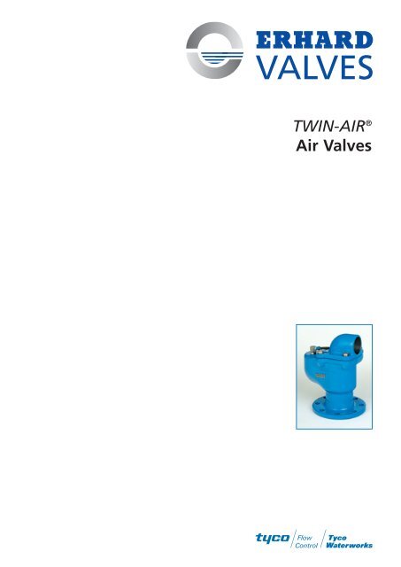
<strong>TWIN</strong>-<strong>AIR</strong> ®Air Valves
<strong>TWIN</strong>-<strong>AIR</strong> ® Air Valvesfor automatic air release and air admission of pipelines<strong>TWIN</strong>-<strong>AIR</strong> ® Air Valves are installedat the high points of closedconduits and downstream orupstream of valves.They may be used for pipe burstcontrol valves, behind throttlingpoints and feeding pumps orturbines.Air Valves are needed for preventingtroublesome air accumulationsin the pipelines, supportingcomplete filling and emptyingof a pipeline, limitingdepression and evacuating gases(air) accumulated during operationunderpressure.Mode of operationWhen the pipeline is empty andpessureless, both orifices of the<strong>TWIN</strong>-<strong>AIR</strong> ® Air Valve are open.Filling the pipelineWhen filling the pipeline withwater, the air is pushed in frontof the water column and can freelydischarge through the largeand the small orifice of the AirValve. When during the fillingprocess the water column reachesthe float point of bothballs, they are raised with therising liquid level. The large orificeis now closed by the largefloat ball. At the same time, thesmall float ball activates a levermechanism closing the small orificeby means of a rubber plug.Air evacuation underpressureWhen under full working pressurethe liquid level descends dueto air accumulation, the smallfloat ball drops reaching thefloat point, and releases thesmall air-exhausting crosssection.At each operating cycle, thesmall orifice is cleaned by meansof a patented cleaning device, apin being moved upwards by theair blown off an being pushedback by spring force after completionof the air-evacuationprocess. Due to the acting differentialpressure the large ballcloses the large orifice whenevacuating air during operation.Emptyingthe pipelineWhen during operation, thepipeline pressure decreases to orbelow atmospheric pressure, thetwo float balls fall and releasethe air outflow and inflow crosssections.Now, the ambient air can flowthrough the Air Valve into thepipeline according to the depressionprevailing in thepipeline.Irresistible design featuresConvincing details➬ Compact design.➬ Streamlined.➬ Lightweight type.➬ Safe operation.➬ Little maintenance.➬ Large air outflow andinflow cross sections.➬ For maximum airoutflow and inflowvelocities.➬ Automatic air releaseunder operating conditions,lever-operated,bore Ø 2.5 mm, withpatented self-cleaningfeature effective ateach operating cycle.➬ Large orifice withconnecting thread.➬ Effective corrosionprotection.➬ Enclosed seal.➬ Pressure ratingup to PN 25.➬ No copper alloy.➬ Self-centeringfloat ball.➬ High-grade materials.Materials andcorrosion protection➬ Body and body coverof ductile cast ironSG GGG-50.➬ Body inside:.➬ Body outside:EKB epoxy coating.➬ Body cover:inside and outsideEKB epoxy coating.➬ Float ball for DN 50 toDN 100 ofmultichamber GRP.➬ Float ball for DN 150and DN 200 ofaustenitic CrNi steel(mat. No. 1.4571).➬ Float guide and floatassembly for evacuationunder pressure ofaustenitic CrNi steel(mat. 1.4571).➬ Body seat of EPDM.➬ Connecting bolts ofstainless steel A4.
<strong>TWIN</strong>-<strong>AIR</strong> ® Air Valvesfor automatic air release and air admission of pipelinesRange of application➬ Automatic air release and air admission ofpipelines for potable water.➬ Special designs on request, e. g. with protectivescreen, with suppressed air-inflow feature, etc.Operating conditions➬ Min. working pressure: 0.2 bar.➬ Max. working pressure: up to 25 bars.➬ Max. working temperature: 70°C.Prod. No., pressure ratings, flangesProd. No. Size Pressure rating Hydrost. test pressure in bars for DesignDN PN body seat dimensionsof the flanges6937 7200 50-200 25 37,5 0,2/25 DIN 28606 PN 256927 7200 100-200 16 24,0 0,2/16 DIN 28605 PN 166917 7200 200 10 15,0 0,2/10 DIN 28604 PN 10Detail: Air evacuation under pressurewith patented cleaning devicePressure springThreaded bushTesting and flushingconnection G 1/2Recommended installation:<strong>TWIN</strong>-<strong>AIR</strong> ® Air Valve with IsolatingShort Body Multamed Gate ValveCleaning pinO-ringSealThreaded sleeveDimensions and weightsSize Height Flange Ext. dimensions Orifice cross Thread- Weight VolumeØ length x width section mm 2 edDN H D L x B large small connection appr.mm PN10 PN25 PN16 mm orif. orif. A kg m 350 317 165 165 165 240 x 191 3850 5 G 21/2 19 0.01580 317 200 200 200 240 x 191 3850 5 G 21/2 19 0.015100 333 235 220 220 240 x 191 3850 5 G 21/2 20 0.015150 385 300 285 285 316 x 222 9500 5 G 4 32 0.029200 385 360 340 340 316 x 222 9500 5 G 4 43 0.029
Air outflow and inflow capacitiesThe suitable valve size is selectedon the basis of the actual workingconditions.Air capacityFor air capacities, see below diagrams: Air evacuation via the largeorifice (filling the pipeline).The air flow rate Q is identicalwith the inflowing water rate. Air evacuation via the smallorifice (under working pressure). Air admission via the large orifice(emtpying the pipeline).The air flow rate Q is identicalwith the outflowing waterrate.Extreme air rate demandIf one single air valve cannotcomply with the specified outflowand inflow requirements,air valves can be fitted inclusters.For large air inflow rates (valveslarger than DN 200), ERHARDDisc Type Air Inlet Valves are theappropriate solution.Recommended limit valuesFilling the pipelineDuring the closing process of the<strong>TWIN</strong>-<strong>AIR</strong> ® Air Valve, for safetyreasons the max. admissiblewater hammer should notexceed P = 3 bars. This is basedon filling the pipeline at a velocityof 0.25 m/sec.Recommended limit valuesEmptying the pipelineThe recommended air velocitywhen emptying the pipeline isV max. =80 m/sec. (referred to theclear air-inflow cross section).Air outflow (large orifice)Air inflow (large orifice)1.5Working pressure P (bar abs)1.41.31.21.11.1DN 50DN 80DN 100DN 150/2000 0,1 0,2 0,3 0,4 0,5 0,6 0,7 0,8 0,9 1,0 1,1 1,2 1,3Working pressure P (bar abs)0,60,70,80,9DN 50DN 80DN 100DN 150/200Air outflow capacity Q (m 3 /s)0,1Air evacuation under pressure(small orifice Ø 2,5 mm)0 0,1 0,2 0,3 0,4 0,5 0,6 0,7 0,8 0,9 1,0 1,1 1,2 1,3 1,4 1,5 1,6Internal pressure P (bar abs)3212 3 4 5 6 7Air inflow capacity Q (m 3 /s)Air evacuation capacity Q (m 3 /h)Postfach 1280 · D-89502 HeidenheimPhone: +49(0)7321 320-0 · Fax: +49(0)7321 320-525http://<strong>www</strong>.erhard.dee-mail: export@erhard.deData corresponding to the latest level of development, modifications reserved.Printed in Germany. 04/0546029EN


