Create successful ePaper yourself
Turn your PDF publications into a flip-book with our unique Google optimized e-Paper software.
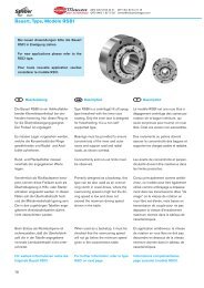
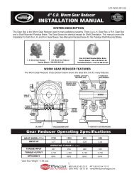
DIST. AUTORIZADO<strong>Air</strong> <strong>Tube</strong> <strong>Disc</strong> <strong>Clutches</strong> <strong>and</strong> <strong>Brakes</strong>®MEX (55) 53 63 23 31QRO (442) 1 95 72 60MTY (81) 83 54 10 18ventas@industrialmagza.comHigh Torque <strong>Clutches</strong>RingVery Low InertiaDrive PlateAssemblyBonded or RivetedShimsHigh Torque<strong>Air</strong>-<strong>Tube</strong>FloatingPlatePressurePlateHubDuctileCenter Plate<strong>Air</strong>tubeHoldingPlateGroovedFriction <strong>Disc</strong>Demountable BackplateRoto-couplingWichita High Torque <strong>Clutches</strong> provide thehighest torque to size ratios of any WichitaClutch. They provide smooth controlledstarts <strong>and</strong> stops <strong>and</strong> are designed forminimum power loss due to low rotatinginertia.• Extremely fast response• No lubrication• High torque to size ratio• Low rotating inertiaSelection RequirementsTo properly select a High Torque Clutch<strong>and</strong> Low Inertia Brake, the followinginformation must be determined.1. Torque necessary to do the work(clutch).2. Rotating inertia to be stopped <strong>and</strong>started.3. Heat generated by each stop/start.4. Torque necessary to stop inertia (brake).5. Shaft size.42
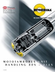
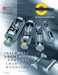
DIST. AUTORIZADO®MEX (55) 53 63 23 31QRO (442) 1 95 72 60MTY (81) 83 54 10 18ventas@industrialmagza.comSelection exampleDataRated Tonnage. . . . . . . . . . . . . . . . . . As RequiredCrankshaft Speed. . . . . . . . . . . . . . . . 30 rpm(Continuous Run)Clutch-Brake Shaft rpm . . . . . . . . . . . 204 rpmCrankshaft Speed. . . . . . . . . . . . . . . . 30 rpmDegrees of Crank to start . . . . . . . . . 90°Degrees of Crank to stop. . . . . . . . . . 90°Connecting Rod Length = b . . . . . . . 36 in.Stroke . . . . . . . . . . . . . . . . . . . . . . . . . 6 in.1/2 of Press Stroke (throw) = a . . . . . . 3 in.WR 2 of Parts on Backshaft . . . . . . . . . 78.2 lb.ft. 2WR 2 of Parts on Crankshaft . . . . . . . . 39,091 lb.ft. 2Material Shear Stress . . . . . . . . . . . . . 45,000 psiBlade Width . . . . . . . . . . . . . . . . . . . . 60 in.Shaft Size. . . . . . . . . . . . . . . . . . . . . . . 4 in.Maximum Material to be Sheared . . x<strong>Air</strong> Pressure Available . . . . . . . . . . . . . 100 psiMotor<strong>Air</strong> ClutchCrankshaftFlywheelBullgearBrakeABCDCalculationsTorque @ Crank= (Material Shear Stress) (x) (Blade Width) (Torque Arm)Torque arm = y = (x) (tan α)c = a + b – x= 3 + 36 – .25= 38.75 in.Cos α= b 2 + c 2 – a 22 bc= (36) 2 + (38.75) 2 – (3) 2(2) (36) (38.75)= .99948α = 1.8478˚cy3 inθThrow ofCrank = a36 In ConnectingRod = bαEFTorque Arm = y = (c) (tan α)= (38.75) (tan 1.8478˚)= (38.75) (.03226)= 1.25 in.Torque @ Crank= (Material Shear Stress) (x) (Blade Width) (Torque Arm)= (45,000) (.25) (60) (1.25)= 843,750 lb.in.1/4 In OffBottomDeadCenterxGTorque @ Clutch= (Torque @ Crank) ÷= 843,750 ÷ 204 rpm30 rpm= 124,081 lb.in.Clutch rpmCrankshaft rpmH43
DIST. AUTORIZADO<strong>Air</strong> <strong>Tube</strong> <strong>Disc</strong> <strong>Clutches</strong> <strong>and</strong> <strong>Brakes</strong>®MEX (55) 53 63 23 31QRO (442) 1 95 72 60MTY (81) 83 54 10 18ventas@industrialmagza.comHigh Torque <strong>Clutches</strong>Clutch SelectionPer the application factors on page 31 a“Back Geared Press is ‘Group C’.”hp Torque 124,081100 rpm = 630 = 630 =197The preliminary clutch selection based on124,081 lb.in. <strong>and</strong> 197 hp/100 rpm is anATD-224 Low Inertia High Torque Clutch.(page 41)A Low Inertia High Torque Clutch was chosenbecause of the continuous duty (non-cyclic)operation having a relatively low heat hprequirement.ATD-224 Low Inertia High Torque Clutch =280 hp/100 rpmRated Torque = 480,000 lb.in @ 100 psiRequired clutch air pressure is:psi = clutch required torque x (100 psi)Catalog rated torque @ 100 psiActual required clutch psiEstimated time to start= Start Angle 60360° Crankshaft rpm= 90˚ 60 = 0.5 Sec.360˚ 30P 1= Line pressure to clutch.P 2= Required pressure to clutch.LN = Natural log.k = Inflation coefficient(ATD-224 H.T. @ 100 psi).= 2,600u = For ATD-224 H.T. Clutch @ 100 psi= 2.5Time to 26% of line pressure.1uLN P1t = [ P1- P2]k1100 2.5t = LN[ 100 - 26]2,600[ ][ ]psi = 124,081 x (100 psi)480,000= 26 psi minimum is required.This application has 100 psi available.Contact velocity of rotating disc is:V c= (Diameter of Center Plate) (π) (rpm)12 in.ft.= 24 ft.12 (π) (204) = 1,282 min.(Ductile iron is not required, see page 31).= 0.027 secondsClutch will be fully inflated at 90˚ of crankshaftrotation.Clutch exhaust time @ 100 psi = E = .078(page 48).Note:This application example is forpreliminary sizing only. Contact aWichita Sales Engineer or thefactory for final selection.Maximum bore for ATD-224 High Torque LowInertia Clutch = 7 in.Check clutch inflation time for 90˚ start angle(see page 48, psi pressure curves)44
DIST. AUTORIZADO®MEX (55) 53 63 23 31QRO (442) 1 95 72 60MTY (81) 83 54 10 18ventas@industrialmagza.comLow Inertia Brake SelectionTo properly size a brake, the total rotatinginertia reflected to the clutch <strong>and</strong> brakeshaft must be known.Alternate shaft WR 2referred to clutch shaft= Alternate Alternate shaft rpm 2shaft WR 2 clutch shaft rpm= 39,091 302204WR 2 referred to = 845.4 lb.ft 2clutch-brake shaft@204 rpmTotal inertia = 78.2 lb.ft. 2Back shaft WR 2Clutch hub &drive plate WR 2 from = 101.0 lb.ft. 2Specification TableEstimate brake WR 2 = 101.0 lb.ft. 2(assume same as clutch)Total WR 2 referred = 1,125.66 lb.ft. 2to clutch-brake(Estimated)Estimated time to stop:[ ][ ]= Start Angle 60360º Crankshaft rpm= 90º 60360º 30The deceleration torque isT = 12 WR 2 Brake rpm32.2 9.5(t)= 12 1125.6 20432.2 9.5 (.5)[ ][ ][ ][ ][ ] [ ][ ] [ ]= .5 Sec.Deceleration Torque = 18,015 lb. in.The hp / 100 rpm for this application is:hp = Torque (lb.in.) = 18,015 = 29 hp / 100 rpm100 rpm 630 630Consult the Specification Table on page 34to select a brake based on torque <strong>and</strong> hp/100 rpm. Under "Duty C", an ATD-214 brakehas 32 hp/100 capacity <strong>and</strong> 55,250 lb.in.torque. The rotating inertia of an ATD-214Low Inertia Brake is 11 lb.ft. 2 . Therefore, theactual rotating inertia reflected to brake is1035.6 lb.ft. 2 .The actual = 12 1035.6 204deceleration torque 32.2 9.5= 16,575 lb.in.Required air pressure is:Brake = Brake required torque x (100 psi)Catalog rated torque @ 100 psi= 16,575 lb.in. x 10055,250 lb.in.= 30 psi minimum[ ] [ ]This application has 100 psi available.The average heat hp each stop= (Brake Torque) x rpm x 1/263,000= 16,575 x 204 x .563,000= 26.8 hpFriction area necessary to absorb heat =heat hp= Heat hp = 26.8Absorbtion rate for .5 sec= 39 in.2.7 .7(see page 160)An ATD-214 Low Inertia Brake has 316 in.2 offriction lining available to absorb heatgenerated by stopping. Maximum bore foran ATD-214 Low Inertia Brake is 4-1/8 inches.Based on the given application data <strong>and</strong>the following calculations, an ATD-224 LowInertia High Torque Clutch <strong>and</strong> ATD-214Low Inertia Brake have been selected ashaving sufficient torque <strong>and</strong> heat dissipationcapacity with minimum diameter <strong>and</strong>sufficient bore capacity.Note:These application examples are forpreliminary sizing only. Contact aWichita Sales Engineer or thefactory for final selection.ABCDEFGH45
DIST. AUTORIZADO<strong>Air</strong> <strong>Tube</strong> <strong>Disc</strong> <strong>Clutches</strong> <strong>and</strong> <strong>Brakes</strong>®MEX (55) 53 63 23 31QRO (442) 1 95 72 60MTY (81) 83 54 10 18ventas@industrialmagza.comHigh Torque <strong>Clutches</strong>SpecificationsSlip Maximum Horsepower Max. <strong>Air</strong>-<strong>Tube</strong>Torque Per 100 RPM Bore Swept VolumeModel Lb. In At Duty Rect. Recommended Friction In. 3Size 100 PSI* Key Clearances Area New WornATD- .3CF A B C D Inches Inches In. 2 Lining Lining106 5,000 8 5.7 2.8 1.4 2 1/16-3/32 39 3 14206 10,000 16 11.4 5.7 2.8 2 1/16-3/32 78 4 14108 11,000 17 12.5 6.2 3.1 2-3/8 1/16-1/8 56 5 30208 22,000 34 25 12.5 6.2 2-3/8 3/32-5/32 112 7 30111 25,000 38 28 14 7 2-5/8 1/16-1/8 114 8 48211 50,000 76 56 28 14 2-5/8 3/32-5/32 228 11 48114 48,000 75 55 27 14 4-1/8 1/16-1/8 158 12 75214 96,000 160 114 55 28 4-1/8 3/32-5/32 316 17 75118 105,000 165 120 60 30 5-1/4 1/16-1/8 264 20 140218 210,000 330 240 120 60 5-1/4 3/32-5/32 528 35 140124 240,000 385 280 140 70 7 3/32-5/32 574 50 250224 480,000 770 560 280 140 7 1/8-3/16 1,148 75 250130 470,000 750 535 270 135 8-1/2 3/32-5/32 827 80 395230 940,000 1500 1070 540 270 8-1/2 1/8-3/16 1,654 120 395136 940,000 1555 1120 560 280 10-1/2 3/32-5/32 1,150 120 770236 1,880,000 3100 2240 1120 560 10-1/2 1/8-3/16 2,300 150 770148 2,360,000 3745 2690 1345 670 18 1/8-3/16 2,010 200 1430248 4,720,000 7490 5380 2690 1345 18 5/32-7/32 4,020 300 1430*Max. recommended air pressure — 100 PSI.Model No.ModelSizeATD-xxxATD-xxxModelTypeLI-HTC for Low Inertia High Torque ClutchVLI-HTC for Very Low Inertia High Torque ClutchNote: Very Low Inertia High Torque <strong>Clutches</strong> are availablein sizes from ATD-108 to ATD-224.46
DIST. AUTORIZADO®MEX (55) 53 63 23 31QRO (442) 1 95 72 60MTY (81) 83 54 10 18ventas@industrialmagza.comALow Inertia High TorqueVery Low Inertia High TorqueHUB HUB HUB HUBModel Total Total & CP & CP Effec. Total Total & DP & DP Effec.Size Wt. WR 2 Wt. WR 2 Wt.† Wt. WR 2 Wt. WR 2 Wt.ATD- Lbs. #Ft. 2 Lbs. #Ft. 2 Lbs. Lbs. #Ft. 2 Lbs. #Ft. 2 † Lbs.106 22.5 1.4 6.40 .24 6.99 — — — — —206 37.7 2.8 12.7 .46 11.38 — — — — —108 60.78 7.33 10.0 .55 12.80 59.2 7.24 8.2 .74 15.83208 79.05 9.65 16.0 .72 19.30 77.21 9.35 15.3 1.5 23.36111 109.4 21.43 15.0 1.35 21.35 110.1 21.79 14.0 .83 28.15211 148.44 28.72 30.0 2.60 39.65 145.74 29.27 26.0 1.60 46.95114 120 31 48 5.6 35 119 23.6 30.4 2.7 38214 171 45 65 11 59 146 34.2 51.8 5.2 52118 284 108 71 14.5 91 278.4 100.5 44.4 7.5 67218 406 177 113 27.6 133 382.6 166.4 66.6 13.4 151124 599 431 131 50 196 566.5 409 107.5 27 231224 783 530 260 101 301 727 494 181 41 273130 1099 1424 212 129 348 — — — — —230 1460 1718 402 244 528 — — — — —136 1762 2554 351 325 620 — — — — —236 2375 3513 784 705 937 — — — — —148 5471 15245 1101 1785 1773 — — — — —248 6802 19150 1942 3335 2459 — — — — —† Weight of internal clutch parts for use in calculating clutch engagement time.BCDEFGH47
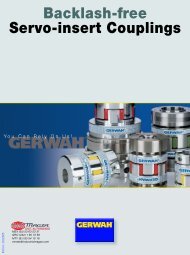
DIST. AUTORIZADO<strong>Air</strong> <strong>Tube</strong> <strong>Disc</strong> <strong>Clutches</strong> <strong>and</strong> <strong>Brakes</strong>®MEX (55) 53 63 23 31QRO (442) 1 95 72 60MTY (81) 83 54 10 18ventas@industrialmagza.com<strong>Air</strong> system dataPSI pressureInflationClutch air pressure during inflation can beclosely estimated by the following:ExhaustClutch air pressure during exhaustcan be closely estimated by the following:Clutch pressureClutch pressurepsipsit ot dt 1timetimet 1=( — ) 1 u — = Time to 95% full inflation3 sec. Kt ot dt eTo clutchbrakeTo clutchbrakeTo clutchbrakeClutch pressure = P 1 ( 1 – 1) psie Ktu(inflation)This equation is accurate from 5% upto 95% P 1.P 1= Line pressure to clutch psiK <strong>and</strong> U = coefficients for specific clutch<strong>and</strong> air pressure from SpecificationTable on page 53.et ot dFlowcontrolFree flowFlowcontrolFree flow= Naperian base log= Time at initiation of signal forinflation sec.= Time delay of air system – sec.Modulating valveOn off valveExhaustExhaust3 way solenoid valveVolume tankRegulator<strong>Air</strong>supplyClutch pressure = (P 1) (R) (E-t) v psi(exhaust)R, E <strong>and</strong> V = coefficients for specific clutch<strong>and</strong> air pressure from SpecificationTable on page 53.t et= Time to exhaust = E from SpecificationTable on page 53.= Time variable – seconds. In theexhaust equation “t” cannotexceed the value of “E” sec.Shown are some of the air systems usedon Wichita clutches. These systems areacceptable for remote operation whereclutch reaction time is not important. Fasterclutch reaction time is accomplished asindicated in the diagram by locating theflow control valve, if required, <strong>and</strong> thesolenoid valve as close as possible to theroto-coupling. Where clutches are locatedon long shafts, the use of quick releasevalves on the clutch will facilitate fasterclutch response.48
DIST. AUTORIZADO®MEX (55) 53 63 23 31QRO (442) 1 95 72 60MTY (81) 83 54 10 18ventas@industrialmagza.comOverlapAA typical clutch-brake torque curve for asingle backshaft press (cyclic application)would appear as shown below.ClutchBTorque (lb-in)t 2BrakeTime (sec.)t Oc = time at which disengaged clutchreceives signalt Cc = time of clutch engagementt 1c = time of clutch full inflationt OB = time at which disengaged brakereceives signalt Bc = time of brake engagementt 1B = time of brake full exhaustt 2T overlapt OC t CC t 1C t OB t BC t 1B= overlap time at which clutch <strong>and</strong>brake are both engagedCDEQuick releasevalveRoto-couplingClutchQuick releasevalveBrakeFFlexiblelineExhaustFlow controlvalve3 waysolenoid valveVolume tankRegulator<strong>Air</strong>supplyFlexiblelineExhaustFlow controlvalve3 waysolenoid valveVolume tankRegulator<strong>Air</strong>supplyGH49
<strong>Air</strong> <strong>Tube</strong> <strong>Disc</strong> <strong>Clutches</strong> <strong>and</strong> <strong>Brakes</strong>DIST. AUTORIZADO®MEX (55) 53 63 23 31QRO (442) 1 95 72 60MTY (81) 83 54 10 18ventas@industrialmagza.comHigh Torque <strong>Clutches</strong>Dimensions (in)Demountable Backplatea - Number of holesb - HolesABCDHIJZjHigh TorquePQkT(SeeNote 1)fLow inertia Very low inertia(Consult factory for drawing before final layout.)ModelSize ATD- A B C D E F G H I J106 8.75 8.000 7.377/7.379 4.19 .06 .562 .69 7.373/7.375 8.000 7.377/7.379206 8.75 8.000 7.377/7.379 4.19 .06 .562 .69 7.373/7.375 8.000 7.377/7.379108 12.12 11.125 8.375/8.378 5.38 .25 .875 1.00 9.281/9.284 10.187 9.285/9.288208 12.12 11.125 8.375/8.378 5.38 .25 .875 1.00 9.281/9.284 10.187 9.285/9.288111 16.00 14.750 11.375/11.378 7.00 .38 1.125 1.25 12.370/12.373 13.500 12.375/12.378211 16.00 14.750 11.375/11.378 7.00 .38 1.125 1.25 12.370/12.373 13.500 12.375/12.378114 18.75 17.500 14.375/14.378 9.43 .38 1.125 1.25 15.121/15.124 16.250 15.125/15.128214 18.75 17.500 14.375/14.378 9.43 .38 1.125 1.25 15.121/15.124 16.250 15.125/15.128118 23.25 22.000 18.250/18.253 12.50 .38 1.125 1.25 19.495/19.498 20.750 19.500/19.503218 23.25 22.000 18.250/18.253 12.50 .38 1.125 1.25 19.495/19.498 20.750 19.500/19.503124 30.00 28.750 24.375/24.378 14.50 .25 1.125 1.25 25.497/25.499 26.750 25.500/25.503224 30.00 28.750 24.375/24.378 14.50 .25 1.125 1.25 25.497/25.499 26.750 25.500/25.503130 37.00 35.500 30.375/30.378 19.25 .25 1.250 1.43 32.118/32.123 33.250 32.125/32.128230 37.00 35.500 30.375/30.378 19.25 .25 1.250 1.43 32.118/32.123 33.250 32.125/32.128136 43.50 42.000 36.375/36.378 23.63 .25 1.500 1.75 38.120/38.123 39.75 38.125/38.128236 43.50 42.000 36.375/36.378 23.63 .25 1.500 1.75 38.120/38.123 39.75 38.125/38.128148 61.00 58.000 52.000/52.005 32.00 .25 1.500 1.75 51.993/51.998 54.000 52.000/52.005248 61.00 58.000 52.000/52.005 32.00 .25 1.500 1.75 51.993/51.998 54.000 52.000/52.005ABCDENotes:FGc - Number of holesd - Tap(See Note 2)1. Roto-couplings, see page 61.2. Quick Release Valves, see page 61.3. VLI Drive Plates available with bondedor riveted pads.RSModelSize ATD- P Q R S T Z a b c d f j k106 — — 4.00 4.50 8.81 .06 4 11/32 4 5/16-18 5/8-18 .69 2.00206 — — 5.19 5.69 8.81 .06 4 11/32 4 5/16-18 5/8-18 .69 3.25108 4.31 3.68 3.63 5.25 11.13 .13 6 17/32 6 1/2-13 1/4" NPT .50 1.50208 5.56 4.93 4.88 6.50 11.13 .13 6 17/32 6 1/2-13 1/4" NPT .50 2.87111 6.63 4.50 4.38 6.50 14.75 .13 6 21/32 6 5/8-11 1/2" NPT .75 2.00211 8.25 6.13 6.13 8.25 14.75 .13 6 21/32 6 5/8-11 1/2" NPT .75 3.75114 7.18 5.13 4.81 6.96 17.50 .13 8 21/32 8 5/8-11 1/2" NPT .88 2.25214 9.13 7.06 6.94 9.00 17.50 .13 8 21/32 8 5/8-11 1/2" NPT .88 4.25118 — 5.90 6.09 7.96 22.00 .13 12 21/32 12 5/8-11 1/2" NPT .81 2.75218 — 8.03 7.91 9.78 22.00 .13 12 21/32 12 5/8-11 1/2" NPT .81 4.75124 8.38 6.81 7.00 8.43 29.00 .13 12 21/32 12 5/8-11 1/2" NPT .56 3.13224 10.94 9.50 9.43 10.88 29.00 .13 12 21/32 12 5/8-11 1/2" NPT .56 5.13130 — — 9.25 16.06* 36.13 .19 18 25/32 18 3/4-10 1-1/2"-12 .88 5.00230 — — 10.31 18.06* 36.13 .19 18 25/32 18 3/4-10 1-1/2"-12 .88 6.25136 — — 10.31 18.87* 41.50 .19 18 1-1/32 18 3/4-10 2" NPT .88 4.25236 — — 13.56 22.13* 41.50 .19 18 1-1/32 18 3/4-10 2" NPT .88 7.50148 — — 15.44 24.00* 59.00 .25 24 1-1/32 24 1-8 2" NPT 1.00 6.00248 — — 19.75 28.31* 59.00 .25 24 1-1/32 24 1-8 2" NPT 1.00 8.75EFG‡ 30" sizes <strong>and</strong> larger furnished with external roto-coupling.HNotes: Very Low Inertia High Torque <strong>Clutches</strong> are available in sizes from ATD-108 to ATD-224. See page 34.For mounting, use socket head cap screws conforming to the ASTM-574-97a.5051
DIST. AUTORIZADO<strong>Air</strong> <strong>Tube</strong> <strong>Disc</strong> <strong>Clutches</strong> <strong>and</strong> <strong>Brakes</strong>®MEX (55) 53 63 23 31QRO (442) 1 95 72 60MTY (81) 83 54 10 18ventas@industrialmagza.comHigh Torque <strong>Clutches</strong>Component Parts3 24167910111213262423251. Hub2. Demountable Backplate203. Socket Head Capscrews274. Ring6. Grooved Friction <strong>Disc</strong>(grooved on one side)2122147. Center Plate9. Grooved Friction <strong>Disc</strong>21. Release Springs10. Pressure Plate22. Flexloc Nut11. Pancake <strong>Air</strong> <strong>Tube</strong>23. Internal Roto-Coupling12. Shims24. ”O“ Ring13. <strong>Air</strong> <strong>Tube</strong> Holding Plate25. Snap Ring14. Socket Head Capscrews26. Flathead Socket Capscrew20. Hex Head Capscrew27. Slotted Flush Nut52
DIST. AUTORIZADO®MEX (55) 53 63 23 31QRO (442) 1 95 72 60MTY (81) 83 54 10 18ventas@industrialmagza.comHigh Torque <strong>Clutches</strong>Inflation CoefficientsModelInflation Coefficients Operating <strong>Air</strong> PressureSize 50 PSI 75 PSI 100 PSIATD- K U K U K U111 393000 3 151000 3 5100 4211 393000 3 151000 3 5100 4114 49000 3 30000 3 17600 3214 49000 3 30000 3 17600 3118 5700 2.8 5700 2.8 7500 3218 5700 2.8 5700 2.8 7500 3124 10400 3 5200 2.7 2600 2.5224 10400 3 5200 2.7 2600 2.5130 940 2.2 1070 2.2 590 2230 940 2.2 1070 2.2 590 2136 77000 3.5 58000 3.5 44000 3.5236 77000 3.5 58000 3.5 44000 3.5148 1200 2.5 1240 3.5 800 2.5248 1200 2.5 1240 3.5 800 2.5ABCDExhaust CoefficientsModelExhaust Coefficients Operating <strong>Air</strong> PressureSize 50 PSI 75 PSI 100 PSIATD- R E V R E V R E V111 480000 .04 4 180000 .05 4 * .056 5211 480000 .04 4 180000 .05 4 * .056 5114 5600 .032 2.5 2200 .044 2.5 910 .064 2.5214 5600 .032 2.5 2200 .044 2.5 910 .064 2.5118 4100 .062 3 9800 .1 4 8500 .104 4218 4100 .062 3 9800 .1 4 8500 .104 4124 280 .06 2 775 .068 2.5 575 .078 2.5224 280 .06 2 775 .068 2.5 575 .078 2.5130 690 .072 2.5 500 .083 2.5 500 .084 2.5230 690 .072 2.5 500 .083 2.5 500 .084 2.5136 86 .048 1.5 76 .056 1.5 1100 .064 1.5236 86 .048 1.5 76 .056 1.5 1100 .064 1.5148 160 .11 2.3 120 .136 2.4 111 .15 2.5248 160 .11 2.3 120 .136 2.4 111 .15 2.5* 1.88 x 10 6EFGH53