VITODENS 200 WB2A - Heatingspares247.com
VITODENS 200 WB2A - Heatingspares247.com VITODENS 200 WB2A - Heatingspares247.com
3 Installation RequirementsPositionMinimum SpacingLHorizontally from a terminal on same wall300mm12inMAdjacent to opening300mm12inNBelow carport200mm8inOFrom adjacent wall300mm12inPFrom adjacent opening window1000mm40inQFrom another terminal600mm24inRMinimum height300mm12inFigure 3/A: Flue Termination Position12
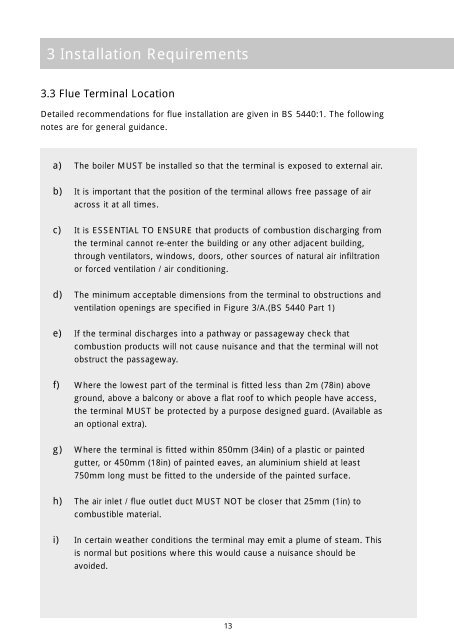
3 Installation Requirements3.3 Flue Terminal LocationDetailed recommendations for flue installation are given in BS 5440:1. The followingnotes are for general guidance.a) The boiler MUST be installed so that the terminal is exposed to external air.b) It is important that the position of the terminal allows free passage of airacross it at all times.c) It is ESSENTIAL TO ENSURE that products of combustion discharging fromthe terminal cannot re-enter the building or any other adjacent building,through ventilators, windows, doors, other sources of natural air infiltrationor forced ventilation / air conditioning.d) The minimum acceptable dimensions from the terminal to obstructions andventilation openings are specified in Figure 3/A.(BS 5440 Part 1)e) If the terminal discharges into a pathway or passageway check thatcombustion products will not cause nuisance and that the terminal will notobstruct the passageway.f) Where the lowest part of the terminal is fitted less than 2m (78in) aboveground, above a balcony or above a flat roof to which people have access,the terminal MUST be protected by a purpose designed guard. (Available asan optional extra).g) Where the terminal is fitted within 850mm (34in) of a plastic or paintedgutter, or 450mm (18in) of painted eaves, an aluminium shield at least750mm long must be fitted to the underside of the painted surface.h) The air inlet / flue outlet duct MUST NOT be closer that 25mm (1in) tocombustible material.i) In certain weather conditions the terminal may emit a plume of steam. Thisis normal but positions where this would cause a nuisance should beavoided.13
- Page 1 and 2: VITODENS 200 WB2AINSTALLATION & SER
- Page 3 and 4: 1 General Information1.1 Appliance
- Page 5 and 6: 2 Technical Specifications2.2 Gener
- Page 8 and 9: 2 Technical Specifications2.6 Hydra
- Page 10 and 11: 3 Installation Requirements3.1 Stat
- Page 14 and 15: 3 Installation Requirements3.4 Vent
- Page 16 and 17: 3 Installation RequirementsFigure 3
- Page 18 and 19: 3 Installation Requirements3.5 Cent
- Page 20 and 21: 3 Installation Requirements3.7 Gas
- Page 22 and 23: 4 Installation ProcedureFigure 4/A:
- Page 24 and 25: 4 Installation Procedure4.2.2 Fitti
- Page 27 and 28: 4 Installation ProcedureFigure 4/E:
- Page 29 and 30: 4 Installation Procedure4.7.2 Verti
- Page 31 and 32: 4 Installation Procedure4.8.2 Verti
- Page 33 and 34: 4 Installation Procedure4.9.1 Elect
- Page 35 and 36: 4 Installation Procedure4.11 Conden
- Page 37 and 38: 5 Commissioning and Testing5.1 Fill
- Page 39 and 40: 5 Commissioning and Testing5.3 Vent
- Page 41 and 42: 5 Commissioning and Testing5.6 Comm
- Page 43 and 44: 5 Commissioning and Testing5.9 Fina
- Page 45 and 46: 6 Routine Servicing6.1 Routine Serv
- Page 47 and 48: 6 Routine Servicing6.4 Combustion C
- Page 49 and 50: 6 Routine Servicing6.8 Re-commissio
- Page 51 and 52: 8 Fault FindingIt is the law that a
- Page 53 and 54: 9 Replacement of PartsBefore commen
- Page 55 and 56: 9 Replacement of Parts9.3 Burnera)
- Page 57 and 58: 9 Replacement of Parts9.7 Air Press
- Page 59 and 60: 9 Replacement of Parts9.10 Limit Th
- Page 61 and 62: 9 Replacement of Parts9.13 CH Therm
3 Installation Requirements3.3 Flue Terminal LocationDetailed recommendations for flue installation are given in BS 5440:1. The followingnotes are for general guidance.a) The boiler MUST be installed so that the terminal is exposed to external air.b) It is important that the position of the terminal allows free passage of airacross it at all times.c) It is ESSENTIAL TO ENSURE that products of combustion discharging fromthe terminal cannot re-enter the building or any other adjacent building,through ventilators, windows, doors, other sources of natural air infiltrationor forced ventilation / air conditioning.d) The minimum acceptable dimensions from the terminal to obstructions andventilation openings are specified in Figure 3/A.(BS 5440 Part 1)e) If the terminal discharges into a pathway or passageway check thatcombustion products will not cause nuisance and that the terminal will notobstruct the passageway.f) Where the lowest part of the terminal is fitted less than 2m (78in) aboveground, above a balcony or above a flat roof to which people have access,the terminal MUST be protected by a purpose designed guard. (Available asan optional extra).g) Where the terminal is fitted within 850mm (34in) of a plastic or paintedgutter, or 450mm (18in) of painted eaves, an aluminium shield at least750mm long must be fitted to the underside of the painted surface.h) The air inlet / flue outlet duct MUST NOT be closer that 25mm (1in) tocombustible material.i) In certain weather conditions the terminal may emit a plume of steam. Thisis normal but positions where this would cause a nuisance should beavoided.13


