Budgit Air Motor Drive Pkg for EndTrucks - Columbus McKinnon ...
Budgit Air Motor Drive Pkg for EndTrucks - Columbus McKinnon ...
Budgit Air Motor Drive Pkg for EndTrucks - Columbus McKinnon ...

Create successful ePaper yourself
Turn your PDF publications into a flip-book with our unique Google optimized e-Paper software.
<strong>Air</strong> <strong>Motor</strong> <strong>Drive</strong> Supplement to113535-02 and 113535-06(Instructions and Parts List <strong>for</strong> BUDGIT®Underhung and Top Running Crane Bridge Kits(1/4 THRU 5 TON RATED LOADS)BUDGIT <strong>Air</strong> <strong>Motor</strong> <strong>Drive</strong>s <strong>for</strong> Crane Bridge Kits use thesame mechanical parts as <strong>for</strong> Electric <strong>Motor</strong> <strong>Drive</strong>s. Theelectric motor, controls and push button of the electricmotor drive are replaced by an air motor. control valve andpendant control assembly.This supplement, which contains instructions and partslists pertaining to the air motor, control valve and pendantcontrol assembly, is to be used in conjunction with therelevant parts of 113535-2 and 113535-6 to providein<strong>for</strong>mation <strong>for</strong> the <strong>Air</strong> <strong>Motor</strong> <strong>Drive</strong>n Bridges.10980CONNECTING BRIDGE TO AIR SERVICE1. The recommended operating air pressure <strong>for</strong> the BUDGIT<strong>Air</strong> <strong>Motor</strong> <strong>Drive</strong>n Bridge is 90 psi. When line pressureexceeds 100 psi (at lii.l motor when the motor is operating),it is recommended that a pressure regulator valve beprovided in the air supply to maintain proper pressure.Never drive this motor with combustible gas.2. A filter lubricator unit (Figure 3) must be installedbetween the air source and the air hose leading to thebridge. These keep air flowing to the motor free of dirt andadd lubricant to the air so internal parts of the motor areconstantly lubricated. Use a good grade of spindle oil,approximate viscosity 180 ssu at 100° F, air powered tooloil, or S.A.E. I0W machine oil. BUDGIT distributors canprovide filter-lubricator units.3. The air intake elbow on the bridge motor should pointaway from the runway beam.a. Use close nipple in the elbow to attach tee as shownin Figure 9. b. Connect motor to nearest filtered andlubricated air source using 3/4" I.D. air hose attachedto tee. Avoid use of hose assemblies of smallerdiameters that will cause air flow restrictions andreduce bridge per<strong>for</strong>mance.c. Provide sufficient hose to reach from air source tofarthest point of bridge travel. BUDGIT Hose Trolleysare one recommended means of keeping hose up outof the way.d. Attach hose assemblies as shown in Figure 11.Figure 3. <strong>Air</strong> Filter and Lubricator UnitLUBRICATIONServicing the air line filter and lubricator unit is of primaryimportance since it is the only source of lubrication <strong>for</strong> thecontrol valve., and air motor. Fill lubricator with good gradeof light spindle oil, air powered tool oil, or S.A.E. IOWmachine oil.MAINTENANCE1. BUDGIT <strong>Air</strong> <strong>Motor</strong> <strong>Drive</strong>n Bridges are built to give longservice, but should be inspected periodically <strong>for</strong> evidenceof damage or wear, particularly when subjected to unusuallysevere operating conditions.2. Inspection of the pendant throttle control assembly.a. Disassembly. (See Figure 11.)(1) Disconnect three air hoses from top of throttlecontrol assembly.(2) Remove wire rope clips holding wire rope straincable <strong>for</strong> pendant throttle control assembly anddisconnect wire rope.(3) Remove two large hex head threaded caps fromthrottle control assembly side opposite controllevers.May, 2005 Copyright 2005, Yale—Lift-Tech, division of <strong>Columbus</strong> <strong>McKinnon</strong> Corporation Part No. 113535-16
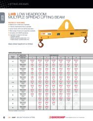
motor an authorized BUDGIT repair station. Donot, under any circumstances, wash sealedbearings or blow off with a high pressure air hose.c. Reassembly. (See Figure 10.)(1) Be<strong>for</strong>e assembly, all parts should be thoroughlycleaned and inspected to determine theirserviceability. Replace all parts that are worn ordamaged.(2) Position assembly vertically with rotor facingupward. Insert push pins in rotor. Place shimgasket and motor body on end plate, using dowelpins <strong>for</strong> positioning. Insert vanes and springs intorotor. Take care that spring tab is positioned in slotof vane.(3) Install six hex socket head screws through frontend plate.(4) Place shim gasket and rear plate on body, usingdowel pins <strong>for</strong> positioning. Press rear bearingonto rotor shaft by pressing on inner race. Bearingouter race should not be bottomed on rear endplate. Shaft must not move laterally in front bearing.Figure 4. Rotor Vane(d) Rotor Vanes and Springs. Inspect the rotorvanes <strong>for</strong> wear, scoring, warpage or other damage.Compare the width of the old vane with a newone to determine the amount of wear that hastaken place on the width. If the old vane is morethan 3/64" less than the new vane (in width), itmust be replaced. An old vane that shows wear onthe thickness must also be replaced. Vanes wornin this manner will eventually fail, resulting incostly repairs, and unexpected down time on thebridge. Warped vanes must also be replaced asthe vanes must move in and out of the rotor slotwithout binding. Inspect leaf springs and centeringpins. Worn areas on springs can cause eventualspring breakage and motor lock up.Replace worn springs, particularly when vanes arereplaced.(e) <strong>Motor</strong> Bearings. Check motor bearings,especially the bearing at the extended shaftend of the motor, <strong>for</strong> excessive looseness orbinding. If bearing requires replacement, send(5) Install six hex head bolts through rear end plate.(6) Replace end cap and gasket and install threefillister screws.(7) Rotor and shaft must turn freely in body.(8) Position motor in proper orientation on bridgegearbox with key in place and fasten with fourhex socket head screws.REPLACEMENT PARTSThe following parts lists and drawings cover parts notincluded in 113535-2 AND 133535-6.The factory recommends complete replacement of the airmotor or gearbox. Service is available, however, from yourauthorized BUDGIT repair station.The numbers assigned to the parts of our variousassemblies in our parts list are not the part numbersused in manufacturing the part. They areidentification numbers, that when given with themodel number, permit us to identify, select ormanufacture and ship the correct part needed.INDEX OF PARTS ILLUSTRATIONFigure No. Title Page No.9 Supply Head Assembly................................................................................................................. 510 <strong>Air</strong> <strong>Motor</strong>........................................................................................................................................ 611 Pendant Throttle Control ............................................................................................................... 7Page 3
12717Figure 9. Supply Head AssemblyRef. Part Qty.No. Number Description Req’d1 BAH-5105 Ring - Internal Retaining 22 BAH-5104 Screen - Exhaust Valve 23 BAH-5103 Muffling Material 24 BAH-5125 Sleeve - Valve 25 BAH-5124 Spring - Valve 26 BAH-5123 Stem - Valve 27 BAH-5114 Gasket - Supply Head 18 BAH-5100 Supply Head 19 BAH-5107 Adaptor Fitting 210 BAH-5106 Screw -Self Tapping 211 BAT-700 Anchor - Cable 112 BAH-5113 Lockwasher 213 BAH-5112 Cap Screw - Hex Socket 214 BAT-701 Tee - Reducing 115 BAT-702 Nipple - Close Pipe 116 BAH-5110 Nipple - Close Pipe 117 BAT-703 Coupling - Reducing 118 BAH-5107 Adaptor Fitting 1Page 4
12442CFigure 10. <strong>Air</strong> <strong>Motor</strong>Ref. Part Qty.No. Number Description Req’dBAT-800 <strong>Air</strong> <strong>Motor</strong> Assembly 11 BAT-801 Rotor and Shaft Assembly 12 BAH-5202 Vane 83 BAH-5203 Spring - Vane 84 BAT-808 Push Pin 45 BAT-802 Body - <strong>Air</strong> <strong>Motor</strong> 16 BAH-5206 Pin - Dowel 47 BAH-5207 Gasket - Body 28 BAT-803 End Plate - <strong>Drive</strong> End 19 BAT-804 Bearing - <strong>Drive</strong> End 110 BAT-805 Shaft Seal 111 BAT-806 O-Ring 112 BAT-807 Cap 113 BAH-5222 Screw 614 BAH-5221 Screw 615 BAH-5215 End Plate - Dead End 116 BAH-5216 Bearing - Dead End 117 BAH-5217 Gasket - End Cap 118 BAH-5218 End Cap - Dead End 1BAH-5219 End Plate Puller Tool (Not Shown) -19 BAH-5220 Screw 320 BAT-809 Screw - Hex Socket Head 3NOTESPage 5
12443AFigure 11. Pendant Throttle ControlRef. Part Qty.No. Number Description Req’d1 BAH-5302 Thimble -Wire Rope 12 BAH-5304 Clip -Wire Rope 23 BAH-5305 Cable - Strain Relief (Specify Length Required)7 ft-, 6 in. <strong>for</strong> 10 ft. Hoist Lift 110 ft. 6 in. <strong>for</strong> 13 ft. Hoist Lift 112 ft. 6 in. <strong>for</strong> 15 ft. Hoist Lift 117 ft. 6 in. <strong>for</strong> 20 ft. Hoist Lift 1BAH-5306 Sleeve - Pressed 1BAT-900 Hose Assembly - SupplyFor 10 ft. Hoist Lift 1BAT-901 For 13 ft. Hoist Lift 1BAT-902 For 15 ft. Hoist Lift 1BAT-903 For 20 ft. Hoist Lift 1BAT-904Hose Assembly - ControlFor 10 ft. Hoist Lift 2BAT-905 For 13 ft. Hoist Lift 2BAT-906 For 15 ft. Hoist Lift 2BAT-907 For 20 ft. Hoist Lift 27 BAH-5316 Tie - Cable 48 BAH-5317 Adaptor Fitting 39 BAT-908 Pendant Throttle Handle Assy - Complete (Includes Ref. Nos. 10 thru 16 Plus Handle)10 BAH-5319 Pin - Throttle Lever 111 BAH-5320 Throttle Lever 112 BAH-5321 Valve - Throttle 213 BAH-5322 Ring - Throttle Valve Seal 214 BAH-5323 Spring - Throttle Valve 415 BAH-5324 Cap - Throttle Valve 216 BAH-5325 Seal -Throttle Valve Cap 2Page 6
MOTOR AND GEAR BOX ASSEMBLY2 thru 7½ Ton <strong>Motor</strong> and Gear Box Assembly14001Ref. Part Qty.No. Number Description Req’d1 905378 Gear Box Assembly 12 <strong>Air</strong> Brake - (contact factory) 13 43891301 <strong>Air</strong> <strong>Motor</strong> 14 22925703 Mounting Plate 15 22925501 Sandwich Plate 16 22746302 Valve 17 227472-1 Muffler 18 53039 Hex Bushing 19* 11443301 Gasket 110* 22746801 Gasket 1*Not ShownNOTESPage 7
AIR MOTOR COMPONENTS14002Ref.Qty.No. Description Req’d1 <strong>Drive</strong> End Cap 12* Seal 13* O-Ring 14 Locknut 15* Lockwasher 16* <strong>Drive</strong> End Bearing 17 Spacer 18 <strong>Drive</strong> End Plate 19 Dowel Pin 410* Spacer Gasket 211 Body 113 Rotor Assembly 314* Push Pin 615* Vane Spring 616* Vane 117 Dead End Plate 118 Dead End Bearing 119 End Cap Gasket 120 Dead End Cap 1* Service Kit 652-308 1*Call Factory For <strong>Air</strong> <strong>Motor</strong> Rebuild KitPage 8
14003Figure 4. Pendant Control Assemblies PC2, PC4 & PC6Quantity RequiredRef.No.PartNumber Description2Station4Station5StationPendant Control Station700AH-401 2 Station 1 -- --700AH-402 4 Station -- 1 --700AH-403 6 Station -- -- 11 700AH-404 O-Ring 2 6 102 700AH-405 O-Ring 2 4 63 700AH-406 Compression Spring 2 4 64 700AH-407 Top Body -- 1 15 700AH-408 Gasket -- -- 16 700AH-409 Intermediate Body -- -- 17 700AH-410 Gasket -- 1 18 700AH-411 Valve Plug 2 4 610 700AH-412 Plunger 2 2 211 700AH-413 Handle 1 1 112 700AH-414 "Raise" Lever 1 1 113 700AH-415 "Lower" lever 1 1 114 700AH-416 Lever Pivot Pin 1 1 115 700AH-417 Plunger -- 2 416 Lever700AH-418 Trolley Left -- 1 1700AH-419 Trolley Right -- 1 1700AH-418 Bridge Forward -- -- 1700AH-419 Bridge Reverse -- -- 123 700AH-422 Hex Head Bolt -- -- 2Page 9
Figure 4. Pendant Control Assemblies PC2, PC4 & PC6 (continued)Quantity RequiredRef.No.PartNumber Description2Station4Station5Station24 700AH-423 Socket Head Full Dog Grub Screw 1 1 126 700AH-424 Reducing Bushing 1 -- --27 700AH-425 Hex Head Bolt -- 2 --17 700AH-426 Male Connectors 3700AH-427 Male Connectors (At Top End) 218 700AH-429 Hose Fittings 619 700AH-430 Hose (Specify Lift) 320 700AH-440 Wire Rope (Specify Lift) 121 700AH-459 Cable Connectors 222 700AH-460 Wire Rope Thimble 1NOTESPage 10
NOTES
Recommended Spare Parts <strong>for</strong> Your <strong>Budgit</strong><strong>Air</strong> <strong>Motor</strong> <strong>Drive</strong>n BridgeCertain parts of your air motor will, in time, require replacement under normal wear conditions.It is suggested that the following parts be purchased as spares <strong>for</strong> future use.1 Set of Oil Seals1 Set of <strong>Motor</strong> Vanes1 Set of <strong>Motor</strong> Springs1 Set of <strong>Motor</strong> PinsNote: When ordering parts always furnish Model Number, Catalog Number and <strong>Motor</strong> NameplateDate of the bridge on which the parts are to be used.Parts <strong>for</strong> your bridge are available from your local authorized BUDGIT repair station.For the location of your nearest repair station, write or phone:YaleŸLift-TechP.O. Box 769Muskegon, MI 49443-0769Phone: 800 742-9269Fax: 800 742-9270WARRANTYWARRANTY AND LIMITATION OF REMEDY AND LIABILITYA. Seller warrants that its products and parts, when shipped, and itswork (including installation, construction and start-up), when per<strong>for</strong>med,will meet applicable specifications, will be of good quality and will befree from defects in material and workmanship. All claims <strong>for</strong> defectiveproducts or parts under this warranty must be made in writingimmediately upon discovery and in any event, within one (1) year fromshipment of the applicable item unless Seller specifically assumesinstallation, construction or start-up responsibility. All claims <strong>for</strong>defective products or parts when Seller specifically assumesinstallation, construction or start-up responsibility and all claims <strong>for</strong>defective work must be made in writing immediately upon discoveryand in any event, within one (1) year from completion of the applicablework by Seller, provided; however, all claims <strong>for</strong> defective productsand parts made in writing no later than eighteen (18) months aftershipment. Defective items must be held <strong>for</strong> Seller’s inspection andreturned to the original f.o.b. point upon request. THE ‘FOREGOINGIS EXPRESSLY IN LIEU OF ALL OTHER WARRANTIESWHATSOEVER, EXPRESS, IMPLIED AND STATUTORY,INCLUDING, WITHOUT LIMITATION, THE IMPLIED WARRANTIESOF MERCHANTABILITY AND FITNESS.B. Upon Buyer’s submission of a claim as provided above and itssubstantiation, Seller shall at its option either (i) repair or replace itsproduct, part or work at either the original f.o.b. point of delivery or atSeller’s authorized service station nearest Buyer or (ii) refund anequitable portion of the purchase price.C. This warranty is contingent upon Buyer’s proper maintenance andcare of Seller’s products, and does not extend to normal wear andtear. Seller reserves the right to void warranty in event of Buyer’s useof inappropriate materials in the course of repair or maintenance, orif Seller’s products have been dismantled prior to submission to Seller<strong>for</strong> warranty inspection.D. The <strong>for</strong>egoing is Seller’s only obligation and Buyer’s exclusiveremedy <strong>for</strong> breach of warranty and is Buyer’s exclusive remedyhereunder by way of breach of contract, tort, strict liability or otherwise.In no event shall Buyer be entitled to or Seller liable <strong>for</strong> incidental orconsequential damages. Any action <strong>for</strong> breach of this agreementmust be commenced within one (1) year after the cause of action hasaccrued.