You also want an ePaper? Increase the reach of your titles
YUMPU automatically turns print PDFs into web optimized ePapers that Google loves.
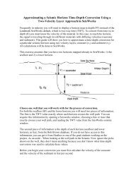
Table Of ContentsList of FiguresFigure 1, SeaBat <strong>8101</strong> System............................................................... 1-1Figure 2, SeaBat <strong>8101</strong> System Block Diagram....................................... 1-2Figure 3, SeaBat Sonar Processor Dimensions (in mm) ........................ 1-7Figure 4, SeaBat <strong>8101</strong> Sonar Processor ................................................ 1-8Figure 5, SeaBat <strong>8101</strong> Sonar Processor, Rear Panel ............................ 1-8Figure 6, SeaBat <strong>8101</strong> Sonar Head...................................................... 1-10Figure 7, Basic SeaBat <strong>8101</strong> Layout ...................................................... 2-1Figure 8, Sonar Head Acoustic Center ................................................... 2-5Figure 9, Cable Schematics ................................................................... 2-6Figure 10, Ping Hold-off Details.............................................................. 2-9Figure 11, SeaBat <strong>8101</strong> Main Sonar Display Screen ............................. 3-2Figure 12, SeaBat <strong>8101</strong> BITE Screen .................................................... 3-3Figure 13, Swath Position....................................................................... 3-4Figure 14, Typical Sound Velocity Values .............................................. 3-8Figure 15, BITE Diagnostic System Information................................... 3-17Figure 16, Receiver Gain Offsets ......................................................... 3-21Figure 17. Snippet Data Sample............................................................. 4-3Figure 18, Snippets Data Comparison.................................................... 4-4Figure 19, Sidescan Beam Geometry..................................................... 4-5Figure 20, Fairing Set, Forward View ..................................................... 4-8Figure 21, Fairing Set, Exploded View ................................................... 4-9Figure 22, Fairing Set, Assembled ......................................................... 4-9Figure 23, Standard (foreground) and Wide Swaths ............................ 4-11Figure 24, Extended Range (ER) Projector .......................................... 4-13Figure 25, Fiber-Optic Interface Unit .................................................... 4-15Figure 26, Transmit Pitch Stabilization ................................................. 4-18Figure 27, SeaBat <strong>8101</strong> Uplink Example................................................ 7-1Figure 28, Depth Gates, With No Roll .................................................... 8-1______________________________________________________________________SeaBat <strong>8101</strong> Operator's Manual TOC-9 Version 3.02