PerforMAX ® IQ HL Static Control System
PerforMAX ® IQ HL Static Control System
PerforMAX ® IQ HL Static Control System

Create successful ePaper yourself
Turn your PDF publications into a flip-book with our unique Google optimized e-Paper software.
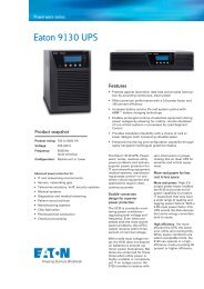
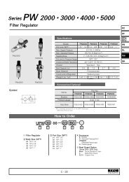
<strong>PerforMAX</strong> <strong>IQ</strong> <strong>HL</strong> <strong>Static</strong> BarHybrid <strong>Static</strong> BarThe rugged <strong>PerforMAX</strong> <strong>IQ</strong> <strong>HL</strong> static bars are tailored to the application.Speed bars are optimized to operate on high speed webs at distances2” to 9” [50mm to 230mm]. Hybrid bars are optimized to operate at 6”to 18” [150 to 460mm] on webs where the web path is somewhatvariable. Each static neutralizing bar features current limiting at eachindividual ion emitting pin to minimize the risk of hazardous electricalshock if the bar is touched while in operation or to eliminate the risk ofexplosion in specific classified areas.Speed <strong>Static</strong> BarRemote DisplayModule<strong>HL</strong>C<strong>HL</strong>Power Supplies++<strong>PerforMAX</strong> <strong>IQ</strong> <strong>HL</strong> & <strong>HL</strong>C Power SupplyThere are two power supply choices for the Performax <strong>IQ</strong> <strong>HL</strong> system.Both Power Supplies are the heart of the <strong>PerforMAX</strong> <strong>IQ</strong> <strong>HL</strong> systembecause it not only provides the high voltage output power producingionization, but they also process all of the system intelligence tomaintain and communicate complete static control. Features includeauto-calibration and dual-axis feedback control. Indicators on the <strong>HL</strong>power supply display system status, power, service status, and faultconditions for mounting outside the hazardous area. While the <strong>HL</strong>Cpower supply is approved for mounting inside classified hazardouslocations. Through the use of the required remote display monitor youcan calibrate with the touch of a button along with neutralizing allcritical indicators such as service status and fault conditions.Communication ModuleWeb Monitor & Probe+<strong>PerforMAX</strong> <strong>IQ</strong> Communication ModuleThe optional <strong>PerforMAX</strong> <strong>IQ</strong> Communication Module creates a remotecomputer interface link between the <strong>IQ</strong> system and a PLC or PC, toprovide a comprehensive real-time summary of performance andsystem alarm data. Ideal for those users that require a historical recordfor lot control or customer review if requested. The module can beconfigured to utilize system supplied software or a number of fieldbuscommunication protocols such as Profibus, EtherNet or Modbus asexamples.<strong>PerforMAX</strong> <strong>IQ</strong> Web MonitorThe optional <strong>PerforMAX</strong> <strong>IQ</strong> Web Monitor Module is an innovative toolused to install a closed-loop, total control, ionization system in aproduction environment. The downstream charge recognition enablesthe <strong>IQ</strong> to maintain maximum performance, and also display thatperformance to the end-user. The web monitor is capable of poweringup to 4 sensor probes on each monitor, and has programmingcapabilities that allow the sensors to be mounted at 1”, 2” or 3” from thesurface. The web monitor also has a programmable alarm feature thatallows the operator to set the alarm threshold for each individual probe.This truly innovative feature puts the operator in control of staticelectricity.W O R L D W I D E L E A D E R S I N S TAT I C C O N T R O L
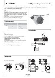
Junction Block for the <strong>PerforMAX</strong> <strong>IQ</strong> <strong>HL</strong>The junction block provides an intermediate connection point for hazardouslocation installations of the <strong>PerforMAX</strong> <strong>IQ</strong> <strong>HL</strong>. The junction box allows quickdisconnect capability for equipment service or replacement, without havingto remove the entire electrical wire/conduit installation.The junction box is approved for Class 1, Division I, Group D; Class II, Division I,Groups F and G and Class III, Division I hazardous locations.Junction BlockInstallation Configurations: Power Supply Inside Hazardous LocationPERFORMAX <strong>IQ</strong> <strong>HL</strong>CPOWER SUPPLYPERFORMAX <strong>IQ</strong>REMOTE DISPLAY MODULECONDUITSEALCONDUITSEALJUNCTION BLOCKOPTIONAL EQUIPMENTRIGIDCONDUITRIGIDCONDUITPERFORMAX <strong>IQ</strong> <strong>HL</strong> SPEED BARHazardous BoundaryGROUNDJUMPERCOMMUNICATIONMODULECONDUITSEALOPTIONAL EQUIPMENTJUNCTION BLOCKRIGIDCONDUITPERFORMAX <strong>IQ</strong> <strong>HL</strong> SPEED BAROPTIONAL EQUIPMENTOPTIONAL EQUIPMENTNOTE 1 - Installation must be in accordance with the National Electrical Code (NEC) or applicablegovernment, state, providence and local regulations. Some conduit runs may require additionalsealing fittings.W O R L D W I D E L E A D E R S I N S TAT I C C O N T R O L
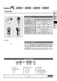
Installation Configurations: Power Supply Outside Hazardous LocationBASICINSTALLATIONHAZARDOUS (CLASSIFIED) LOCATIONNON-HAZARDOUS (UNCLASSIFIED) LOCATIONPERFORMAX <strong>IQ</strong> <strong>HL</strong> POWER SUPPLYRIGIDCONDUITGROUNDJUMPERAC TO 24VDC ADAPTER(UL LISTED)90-240 VAC+ALTERNATE INSTALLATIONWITH COMMUNICATIONMODULE & JUNCTION BLOCKPERFORMAX <strong>IQ</strong> <strong>HL</strong> POWER SUPPLYSEE NOTE-1JUNCTION BLOCKMAX.GROUNDJUMPERAC TO 24VDC ADAPTER(UL LISTED)90-240 VACOPTIONAL EQUIPMENTCOMMUNICATION MODULENOTE 1 - Installations with greater than 18” of conduit between <strong>Static</strong> Bar and <strong>HL</strong>Junction Block may require additional sealing fittings.Hazardous BoundaryAC TO 24VDC ADAPTER(UL LISTED)OPTIONAL EQUIPMENTTO COMPUTER90-240 VAC+WEB MONITORINSTALLATIONWEB MONITORWEB MONITORPROBEGROUNDJUMPERPERFORMAX <strong>IQ</strong> <strong>HL</strong> POWER SUPPLYAC TO 24VDC ADAPTER(UL LISTED)90-240 VACOPTIONAL EQUIPMENTW O R L D W I D E L E A D E R S I N S TAT I C C O N T R O L
Specifications<strong>PerforMAX</strong> <strong>IQ</strong> Web Monitor<strong>PerforMAX</strong> <strong>IQ</strong> Communication ModuleInput Power24VDC, 0.25A from <strong>PerforMAX</strong> <strong>IQ</strong> (BPS) systemInput Power24VDC, 1.0A from <strong>PerforMAX</strong> <strong>IQ</strong> (BPS) system/AC adapterProbe QuantityDimensionsWeightMax Operating TempHousingTotal 4 probes maximum/BPS202mm (L) x 123mm (W) x 106mm (H); [7.95”(L)x 4.84” (W) x 4.17” (H)]1.12 kg [2.48 lbs.]43°C [110°F]Aluminum, black epoxy powder coatedCommunication ModuleDimensionsWeightMax Operating TempHousingAnybus CompactCom, see Replacement Parts/AdditionalItems section of manual for protocols available202mm (L) x 123mm (W) x 55mm (H),; [7.95” (L)x 4.84” (W) x 2.16” (H)]0.77 kg [1.70 lbs.]43ºC [110ºF]Aluminum, black epoxy powder coatedDimensions Drawing<strong>PerforMAX</strong> <strong>IQ</strong> Web Monitor Dimension DrawingDimensions Drawing<strong>PerforMAX</strong> <strong>IQ</strong> Communication ModuleDimension DrW O R L D W I D E L E A D E R S I N S TAT I C C O N T R O L
Specifications<strong>PerforMAX</strong> <strong>IQ</strong> ProbeProbeOperating DistanceInstallation LocationInput PowerPurge ConnectionPurge FlowDimensionsWeightMax Operating TempHousingCommunication CableLength25mm [1”], 50mm [2”], 75mm [3”] firmware selectableDownstream of <strong>IQ</strong> static barfrom <strong>PerforMAX</strong> <strong>IQ</strong> Web Monitor1/4” tube quick connect0.85 m3/h [0.5 cfm] to 5.0 m3/h [3.0 cfm], (1 psi max)clean, dry air110mm (L) x 35mm (W) x 37mm (H); [4.33” (L)x 1.38” (W) x 1.46” (H)]0.22 kg [0.48 lbs.]43°C [110°F]Aluminum and Stainless Steel50 ft., can be cut to length duringinstallation<strong>PerforMAX</strong> <strong>IQ</strong> Remote Display ModuleInput Power 24V , 2.0A (maximum system current)DimensionWeightMax Operating TempHousing202mmL x 123mmW x 58mmH[7.95”L x 4.85”W x 2.28”H]0.7 kg [1.5 lb]43°C [110°F]Aluminum, black epoxy powder coatedDimensions Drawing<strong>PerforMAX</strong> <strong>IQ</strong> Web Monitor ProbeDimensions Drawing<strong>PerforMAX</strong> <strong>IQ</strong> Remote Display ModuleP/N: 5201061 Rev. C2257 North Penn Road • Hatfield, PA 19440Phone: 1.800.203.3419 • Fax: 215.822.3795www.simco-static.com • customerservice@simcomail.com