Create successful ePaper yourself
Turn your PDF publications into a flip-book with our unique Google optimized e-Paper software.
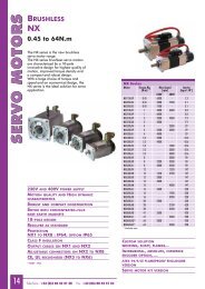
Hardware<strong>Contents</strong>Chapter 1Introduction of FATEK FBS Series PLC1.1 Appearance of Main Unit................................................................................................................. H1-11.2 Appearance of Expander/Module................................................................................................... H1-21.3 Appearance of Communication Expansion Module ..................................................................... H1-41.4 List of FBS-PLC Models .................................................................................................................. H1-51.5 Specifications of Main Unit............................................................................................................... H1-71.6 Environmental Specifications .......................................................................................................... H1-81.7 Connection Diagrams of Various Models ...................................................................................... H1-91.7.1 NC Control Main Unit................................................................................................................ H1-91.7.2 Basic/Advanced Main Unit.......................................................................................................H1-101.7.3 Digital I/O Expander.................................................................................................................. H1-121.7.4 Digital I/O Expansion Module................................................................................................... H1-131.7.5 High-Density Digital I/O Expansion Module ........................................................................... H1-141.7.6 Numeric I/O Expansion Module .............................................................................................. H1-141.7.7 Analog I/O Expansion Module................................................................................................. H1-141.7.8 Temperature Input Module ...................................................................................................... H1-151.7.9 Expansion Power...................................................................................................................... H1-151.7.10 Communication Module (CM) ............................................................................................... H1-161.7.11 Communication Board (CB) .................................................................................................. H1-171.8 Drawings with External Dimensions ............................................................................................... H1-18Chapter 2System Architecture2.1 Single-Unit System of FBS-PLC..................................................................................................... H2-12.2 Formation of Multiple Units.............................................................................................................. H2-22.2.1 Connection of multiple FBS-PLC ............................................................................................ H2-22.2.2 Connection of FBS-PLC with host computer or intelligent peripherals................................ H2-3Chapter 3Expansion of FBS-PLC3.1 I/O Expansion ................................................................................................................................... H3-1
3.1.1 Digital I/O Expansion and I/O Numbering............................................................................... H3-13.1.2 Numeric I/O Expansion and I/O Channel Mapping ............................................................... H3-33.2 Expansion of Communication Port................................................................................................. H3-4Chapter 4Installation Guide4.1 Installation Environment................................................................................................................... H4-14.2 PLC Installation Precautions ........................................................................................................... H4-14.2.1 Placement of PLC..................................................................................................................... H4-14.2.2 Ventilation Space ...................................................................................................................... H4-24.3 Fixation by DIN RAIL........................................................................................................................ H4-34.4 Fixation by Screws ........................................................................................................................... H4-44.5 Precautions on Construction and Wiring........................................................................................ H4-6Chapter 5Wiring of Power Supply, Power Consumption Calculation, andPower Sequence Requirement5.1 Specifications and Wiring of AC Power Sourced Power Supply ................................................. H5-15.2 Specifications and Wiring of DC Power Sourced Power Supply................................................. H5-25.3 Residual Capacity of Main/Expansion Units and Current Consumption of Expansion Module………........................................................................................................................................................ H5-45.3.1 Residual Capacity of Main Unit/Expansion Unit..................................................................... H5-45.3.2 Maximum Current Consumption of Expansion Module........................................................ H5-55.4 Requirement on Power Sequence of Main Unit and Expansion Unit/Module .......................... H5-6Chapter 6Digital Input (DI) Circuits6.1 Specifications of Digital Input (DI) Circuits...................................................................................... H6-16.2 Structure and Wiring of 5VDC Ultra High Speed Differential Input Circuit .................................. H6-26.3 24VDC Single-End Input Circuit and Wiring for SINK/SRCE Input............................................. H6-3Chapter 7Digital Output (DO) Circuits7.1 Specifications of Digital Output Circuits.......................................................................................... H7-17.2 5VDC Ultra High Speed Line-Driver Differential Output Circuit and its Wiring ........................... H7-37.3 Single-End Output Circuit ................................................................................................................ H7-37.3.1 Structure and Wiring of Single-End Relay Output Circuit...................................................... H7-37.3.2 Structure and Wiring of Single-End Transistor SINK & SRCE Output Circuit..................... H7-4
7.3.3 Structure and Wiring of Single-End TRIAC Output Circuit.................................................... H7-57.4 Speed up the Single-End Transistor Output Circuit (only applicable to high and intermediate-speed)......................................................................................................................................................... H7-67.5 Output Device Protection and Noise Suppression........................................................................ H7-67.5.1 Protection of Relay Contact and Noise Suppression ............................................................ H7-67.5.2 Protection of Transistor and Noise Suppression.................................................................... H7-8Chapter 8Test Run, Monitoring and Maintenance8.1 Inspection after Wiring and before First Time Power on............................................................... H8-18.2 Test Run and Monitoring ................................................................................................................. H8-18.3 LED Indications of Main Units and Troubleshooting..................................................................... H8-28.4 Maintenance ..................................................................................................................................... H8-48.5 The charge of battery & recycle of used battery............................................................................ H8-4
HardwareChapter 1Introduction of FATEK FBS Series PLCThe FATEK FBSSeries PLC is a new generation of micro PLC equipped with excellent functions comparable to medium orlarge PLC, with up to five communication ports. The maximum I/O numbers are 256 points for Digital Input (DI) and DigitalOutput (DO), 64 words for Numeric Input (NI) and Numeric Output (NO). The Main Units of FBS are available in three types: MA(Economy Type), MC (High-Performance Type), and MN (High-Speed NC Type). With the combination of I/O point ranges from10 to 60, a total of 17 models are available. Fourteen DI/DO and 12 NI/NO models are available for Expansion Units/Modules.With interface options in RS232, RS485, USB and Ethernet, the communication peripherals are available with 14 boards andmodules. The various models are described in the following:1.1 Appearance of Main UnitAll the Main Units of FBS-PLC have the same physical structure. The only difference is the case width. There are four differentcase sizes, which are 60mm, 90mm, 130mm, and 175mm. The figure below will use the Main Unit case of the FBS-24MC asan example for illustration:3489 16 15 18 201max.400mA24V OUTS/SX0X1X2X3X4X5X6X7X8X10 X12X9 X11 X1312max.400mA24V OUTS/SX0X1X2X3X4X5X6X7X8X9X10X11X12X130 I 2 34 5 6 78 9 I0 III2 I3IN ( X )0 I 2 34 5 6 78 9 I0 III2 I3IN ( X )POWPOWPROGRAMMABLECONTROLLERRUNERRRUNERRTXRXTXRX6INAC100~240VC0Y0Y1C2Y2PORT0Y3Y4C40 I4 58 9Y5OUT( Y )26C637Y6Y7Y8Y9SINKSRCE11INAC100~240VC0Y0Y1C2Y2Y3Y4C4OUT( Y )0 I 2 34 5 6 78 9Y5C6Y6Y7Y8Y9SINKSRCE5 7 2(Front view without Communication Board)10 3171519(Front view with cover plate removed)1314max.400mATXRXPORT2IN24V OUTS/SPORT1AC100~240VC0TXRXY0X0Y1X1PROGRAMMABLECONTROLLERC2X2TXY2X3PORT0Y3X4RXY4X5C4X60 I 2 34 5 6 78 9 I0 III2 I30 I 2 34 5 6 78 9Y5X7POWRUNERROUT( Y )C6X8IN ( X )Y6X9Y7X10Y8X11Y9X12X13SINKSRCE1 35mm-width DIN RAIL2 DIN RAIL tab3 Hole for screw fixation (4.52)4 Terminals of 24VDC power input and digital input(Pitch 7.62mm)5 Terminals of main power input and digital output(Pitch 7.62mm)6 Standard cover plate (without communicationboard)7 Cover plate of built-in communication port (Port 0)(Front view with CB-22 Board installed)H1-1
8 Indicators for transmit (TX) and receive (RX) status of built-in communication port (Port0).9 Indicator for Digital Input (Xn).10 Indicator for Digital Output (Yn).11 Indicator for system status (POW, RUN, ERR).12 I/O output expansion header cover [units of 20 points or beyond only], with esthetic purpose and capable of securingexpansion cable.13 FBS-CB22 Communication Board (CB).14 FBS-CB22 CB cover plate (each CB has its own specific cover plate)15 Screw holes of communication board.16 Connector for communication board (for CB2, CB22, CB5, CB55, and CB25)17 Connector for Communication Module (CM) (only available in MC/MN model, for CM22, CM25, CM55, CM25E, andCM55E connection).18 Connector for Memory Pack.19 Connector for built-in communication port (Port 0) (With USB and RS232 optional, shown in the figure is for RS232)20 I/O output expansion header (only available in units with 20 points or beyond), for connecting with cables fromexpansion units/modules.1.2 Appearance of Expansion Unit/ModuleThere are three types of cases for expansion units/modules. One type uses the same case as main unit that of the 90mm,130mm, and 175mm, while the other two have thinner 40mm and 60mm cases, which are for expansion modules. Allexpansion cables (left) of expansion units/modules are flat ribbon cables (6cm long), which were soldered directly on the PCB,and the expansion header (right) is a 14Pin Header, with this to connect the right adjacent expansion units/modules. In thefollowing, each of the three types of expansion units/modules is described as an example:Expansion unit/module with 90mm, 130mm, or 175mm width case: [-24EA(P), -40EA(P), -60EA(P), -TC16,-RTD16] Screw hole φ 4.5×2Expansion cableconnector24V INS/SDigital inputterminal blockX1X2X3X4X5X6X7X8I 2 3 45 6 7 89 I0 I I I2I3 I4IN ( X )Input status indicatorX9 X11 X13X10 X12 X14Output expansionheader cover plateFront view of output expansionheader with cover plate removedPROGRAMMABLECONTROLLERPOWC1Y2 Y3Y1 C3 Y4Y5C5Y6OUT ( Y )I 2 3 45 6 7 89 I0C7Y7Y8Y9Y10SINKSRCEOutput expansionDigital output terminal block andMain power input (for EAP)DIN RAIL tabOutput status indicatorH1-2
Expansion unit/module with 60mm width case: (-16EA, -16EY, -20EX)Screw hole φ 4.5×2I/O terminal blockOutput expansioncover plateOutput expansion slotS/SX1 X3 X5 X7X2 X4 X6 X8Front view of output expansionslot with cover plate removedOutput status indicatorI 2 3 4 56 7 8IN ( X )FATEKPOWOUT ( Y )I 2 3 4 56 7 8Y1 Y3 Y4 Y5 Y7C1 Y2 C3 C5 Y6 Y8SINKSRCEOutput expansion slotExpansion cableconnectorI/O terminal blockDIN RAIL tabExpansion module with 40mm width case: (-8EA, -8EY, -8EX, -6AD, -2DA, -4DA, -4A2D, -7SG, -TC2, -TC6,-RTD6, -CM5H)Screw hole φ4.5×2I/O terminal blockOutput expansion headercover plateInput statusindicator Front view of output expansionslot with cover plate removedS/SX1 X3X2 X4Output statusindicator I 2 3 4IN ( X )FATEKPOWIOUT ( Y )2 3 4SINKSRCEY1 Y2 Y3C1 C3 Y4Expansion cableconnector I/O terminal blockOutput expansion headDIN RAIL tabH1-3
Expansion module with 40mm width case: (-24EX, -24EYT, -32DGI)Screw hole φ 4.5×2Input statusindicator I 2 3 4 5 6 7 89 I0 II I2 I3 I4 I5 I6I7 I8 I9 20 2I 22 23 24FATEKIN ( X )POWOutput expansionheader cover plateFront view of output expansionheader with cover plateExpansion cableconnectorV1+X2X4X6X8V2+X10X12X14X16V3+X18X20X22X24X1X3X5X7V1-X9X11X13X15V2-X17X19X21X23V3-Output expansionDIN RAIL tabI/O Header socket1.3 Appearance of Communication Expansion ModuleThe Communication Module (CM) of FBS-PLC has a 25mm-width case, which can be used in the following seven modules:-CM22, -CM25, -CM55, -CM25E, -CM55E, -CM25C, -CM5R.Screw holeφ 4.5×2Ethernet network(Port 4)Port 4Communication SocketETHERNETPORT4 (RS485)361 TX2+GT NRUNLNKRXTXRXPort4Communication indicatorTerminator Switch(T: ON, N:OFF)Communication module expansion cableconnector (to be plugged in main unit 1717 )PORT3 (RS232)TXRXPort 3Communication FBs-CM25EDIN RAIL tab Port3 CommunicationH1-4
1.4 List of FBS PLC ModelsItem Name Model Number SpecificationsFBS-20MN2 points 7920KHz 5VDC differential input, 10 points 24VDC digital input (20KHz), 2 points 7920KHz5VDC differential output, 6 points (R/T/S) digital output (Model “T” 6 points 20KHz output), 1 RS232or USB port (expandable up to 5), built-in RTC, detachable terminal block4 points 920KHz 5VDC digital differential input, 16 Points 24VDC digital input (20KHz for 12 Points),NC ControlFBS-32MN 4 points 7920KHz 5VDCdigital differential output, 8 Points (R/T/S) digital output (Model “T” 4 PointsMain Unit20KHz output), 1 RS232 or USB port (expandable up to 5), built-in RTC, detachable terminal block8 points 7920KHz 5VDC digital differential input, 20 Points 24VDC digital input (20KHz for 8 points),FBS-44MN 8 points 7920KHz 5VDCdigital differential output, 8 points (R/T/S) digital output (Model “T” 4 Points20KHz output), 1 RS232 or USB port (expandable up to 5), built-in RTC, detachable terminal block6 points 24VDC digital input (2 points 100KHz4 points 20KHz), 4 points (R/T/S) digital outputFBS-10MCXY (Model “T” 2 points 100KHz2 points 20KHz output), 1 RS232 or USB port (expandable up to 5),built-in RTC, I/O is not expandable8 points 24VDC digital input (2 points 100KHz6 points 20KHz), 6 points (R/T/S) digital outputFBS-14MCXY (Model “T” 2 points 100KHz4 points 20KHz output), 1 RS232 or USB port (expandable up to 5),built-in RTC, I/O is not expandable12 points 24VDC digital input (2 points 100KHz10 points 20KHz), 8 points (R/T/S) digital outputFBS-20MCXY (Model “T” 2 points 100KHz6 points 20KHz output), 1 RS232 or USB port (expandable up to 5),built-in RTCAdvancedMain UnitBasicMain UnitFBS-24MCXYFBS-32MCXYFBS-40MCXYFBS-60MCXYFBS-10MAFBS-14MAFBS-20MAFBS-24MAFBS-32MAFBS-40MAFBS-60MAExpansionFBS-EPOW-PowerFBS-24EAPDigitalFBS-40EAPExpansion Unit FBS-60EAPDigital I/O ModuleDigitalExpansionUnitHigh-DensityDigitalExpansionModuleFBS-8EAFBS-8EXFBS-8EYFBS-16EAFBS-16EYFBS-20EXFBS-24EAFBS-40EAFBS-60EAFBS-24EXFBS-24EYT14 points 24VDC digital input (2ppoints 100KHz12 points 20KHz), 10 points (R/T/S) digital output(Model “T” 2 points 100KHz6 points 20KHz output), 1 RS232 or USB port (expandable up to 5),built-in RTC, detachable terminal block20 points 24VDC digital input (2 points 100KHz14 points 20KHz), 12 Points (R/T/S) digital output(Model “T” 2 points 100KHz6 points 20KHz output), 1 RS232 or USB port (expandable up to 5),built-in RTC, detachable terminal block24 points 24VDC digital input (2 points 100KHz14 points 20KHz), 16 points (R/T/S) digital output(Model “T” 2 points 100KHz6 points 20KHz output), 1 RS232 or USB port (expandable up to 5),built-in RTC, detachable terminal block36 points 24VDC digital input (2 points 100KHz14 points 20KHz), 24 points (R/T/S) digital output(Model “T” 2 points 100KHz6 points 20KHz output), 1 RS232 or USB port (expandable up to 5),built-in RTC, detachable terminal block6 points 24VDC digital input (up to 10KHz in 4 points), 4 Points (R/T/S) digital output (Model “T” has4 points 10KHz output), one RS232 or USB port (can be expanded up to 3), I/O is not expandable8 points 24VDC digital input (up to 10KHz in 4 points), 6 points (R/T/S) digital output (Model “T” has4 points 10KHz output), one RS232 or USB port (can be expanded up to 3), I/O is not expandable12 points 24VDC digital input (up to 10KHz in 4 points), 8 points (R/T/S) digital output (Model “T”has 4 points 10KHz output), one RS232 or USB port (can be expanded up to 3)14 points 24VDC digital input (up to 10KHz in 4 points), 10 points (R/T/S) digital output (Model “T”has 4 points 10KHz output), one RS232 or USB port (can be expanded up to 3)20 points 24VDC digital input (up to 10KHz in 4 points), 12 points (R/T/S) digital output (Model “T”has 4 points 10KHz output), one RS232 or USB port (can be expanded up to 3)24 points 24VDC digital input (up to 10KHz in 4 points), 16 points (R/T/S) digital output (Model “T”has 4 points 10KHz output), one RS232 or USB port (can be expanded up to 3)36 points 24VDC digital input (up to 10KHz in 4 points), 24 points (R/T/S) digital output (Model “T”has 4 points 10KHz output), one RS232 or USB port (can be expanded up to 3)Power supply for expansion module, with single 5VDC and dual 24VDC voltage output and up to20VA capacity14 points 24VDC digital input, 10 points (R/T/S) digital output, built-in power supply24 points 24VDC digital input, 16 points (R/T/S) digital output, built-in power supply36 points 24VDC digital input, 24 points (R/T/S) digital output, built-in power supply4 points 24VDC digital input, 4 points (R/T/S) digital output8 points 24VDC digital input8 points (R/T/S) digital output8 points 24VDC digital input, 8 points (R/T/S) digital output16 points (R/T/S) digital output20 points 24VDC digital input14 points 24VDC digital input, 10 points (R/T/S) digital input24 points 24VDC digital input, 16 points (R/T/S) digital output36 points 24VDCdigital input, 24 points (R/T/S) digital output24 points high-density 24VDC digital input, 30-Pin Header with latch24 points high-density transistor Sink type digital output (0.1A max.), 30-Pin Header with latchH1-5
Numeric I/O ModuleItem Name Model Number Specifications1 set (8 digits) 7 segment LED display (or 64 Points independent LED) output display module,FBs-7SG1Numeric I/O16-Pin Header connector2 set (16 digits) 7 segment LED display (or 128 Points independent LED) output display module,Expansion FBs-7SG216-Pin Header connectorModule8 set 4 digits (total 32 digits) Thumbwheel switch (or 128 Points independent switch) multiplex inputFBs-32DGImodule, 30-Pin Header connectorAnalogExpansionModuleTemperatureInputModuleCommunicationExpansionModuleFBs-6ADFBs-2DAFBs-4DAFBs-4A2D6 channel, 14 bits analog input module (-10V~0V~+10V or -20mA~0mA~+20mA)2 channel, 14 bits digital output module (-10V~0V~+10V or -20mA~0mA~+20mA)4 channel, 14 bits digital output module (-10V~0V~+10V or -20mA~0mA~+20mA)4 channel, 14 bits analog input 2 channel, 14 bits digital output combo analog module(-10V~0V~+10V or -20mA~0mA~+20mA)FBs-TC2 2 channel thermocouple temperature input module with 0.1 resolutionFBs-TC6 6 channel thermocouple temperature input module with 0.1 resolutionFBs-RTD6 6 channel RTD temperature input module with 0.1 resolutionFBs-TC16 16 channel thermocouple temperature input module with 0.1 resolutionFBs-RTD16 16 channel RTD temperature input module with 0.1 resolutionFBs-CM22FBs-CM55FBs-CM25FBs-CM25EFBs-CM55E2 port RS232 (Port3Port4) communication module2 port RS485 (Port3Port4) communication module1 port RS232 (Port3)1 port RS485 (Port4) communication module1 port RS232 (Port3)1 port RS485 (Port4)Ethernet network interface communication module1 port RS485 (Port3)1 port RS485 (Port4)Ethernet network interface communication interfaceFBs-CM25C General purpose RS232 RS485 Converter with optical isolationFBs-CM5RFBs-CM5HGeneral purpose RS485 Repeater with optical isolationGeneral purpose 4-port RS485 HUB with optical isolationFBs-CB21 port RS232 (Port2) communication boardFBs-CB222 port RS232 (Port1Port2) communication boardCommunicationFBs-CB51 port RS485 (Port2) communication boardExpansionFBs-CB552 port RS485 (Port1Port2) communication boardBoardFBs-CB251 port RS232 (Port1)1 port RS485 (Port2) communication boardFBs-CBE1 port Ethernet communication boardFBs-232P0-9F-150 FBs-Main unit Port0 RS232 to 9Pin female D-Sub communication cable, 150cm longCommunicationFBs-232P0-9M-400 FBs-Main unit Port0 RS232 to 9Pin male D-Sub communication cable, 400cm longCableFBs-USBP0-180 FBs-Main unit Port0 USB communication cable (standard USB A B)FBs-PLC Program memory pack with 20Kword program, 20Kword register, and write protectionMemory Pack FBs-PACKswitchFP-07CHand held programmer for FBs-PLCProgrammingDevice WinProladder WinProladder Programming software for WindowsOthers16/7 SegmentLEDDisplay BoardFATEK Comm. ServerFBS-XTNRHD30-22AWG-200Simple People FB-DAP-B(R)Human Machi--ne Interface FB-DAP-C(R)CARD-1RFID CardCARD-2Education andTraining KitFATEK DDE communication serverExtension cable adapterInclude 22AWG I/O cable for 30Pin Header connector, 200cm long ( for FBs-24EX, -24EYT, and-32DGI)DBAN.8(DBAN.8LEDR) 0.84 16 segment display board (with red LED installed )DBAN2.3(DBAN2.3LEDR) 2.34 16 segment display board (with red LED installed )DB.56 (DB.56LEDR) 0.56 8 7 segment display board (with red LED installed)DB.8 (DB.8LEDR) 0.88 7 segment display board (with red LED installed)DB2.3 (DB2.3LEDR) 2.3 8 7 segment display board (with red LED installed)DB4.0 (DB4.0LEDR) 4.0 4 7 segment display board (with red LED installed)FBs-TBOX1. Blankrelay outputTtransistor outputSTRIAC output2. BlankSinkNPNJSourcePNP3. Blankbuilt-in RS232 portUbuilt-in USB port4. Blank100~240VAC power supply D24VDC power supply5. Specifications are subject to changes without further notice.162 LCD character display, 20key keyboard, 24VDC power supply, RS-485 communicationinterface (suffixed R means wireless read card module included)162 LCD character display, 20key keyboard, 5VDC power supply, RS232 communication interface(suffixed R means wireless read card module included)Read-only wireless card (for FB-DAP-BR/CR)Read/Write wireless card(for FB-DAP-BR/CR)46cm × 32cm × 16cm suitcase, containing FBs-24MCT main unit, FBs-CM25E communicationmodule (RS232 RS485 Ethernet network), 14 simulated input switches, 10 external relayisolation output, Doctor terminal outlet I/O, peripherals such as stepping motor, encoder, 7 segmentdisplay, 10 of 10LED indicator, thumbwheel switch, and 16key keyboard.H1-66. XY(optional),The expanding 120KHz inputs(X) and output(Y), thereare 1~6 Points can be expanded for both X,Y.Example:FBs-24MCT-21,Its means expanding 2 points of 120KHzinput(total 4 points) and 1 point of 120 KHz output(total 3 points).And FBS-24MCT-02 means only expanding 2 points of 120KHzoutput(total 4 points).
1.5 Specifications of Main Unit“*” Default SettingsExecution SpeedSpace of Control ProgramItem Specification Note0.33uSper Sequence Command20K WordsProgram Memory FLASH ROM or SRAMLithium battery for Back-upSequence Command 36Application Command 300 (113 types) Include Derived CommandsFlow Chart (SFC) Command 4Single PointBIT StatusX Output Contact(DI) X0X255 (256)Y Output Relay(DO) Y0Y255 (256)TR Temporary Relay TR0TR39 (40)MSCorresponding to External Digital InputPointCorresponding to External Digital OutputPointM0M799 (800)*Can be configured as retentive typeNon-retentiveInternal RelayM1400M1911 (512)Retentive M800M1399 (600)* Can be configured as non-retentive typeSpecial Relay M1912M2001 (90)Step RelayNon-retentive S0S499 (500)*S20~S499 can be configured asretentive typeRetentive S500S999 (500)* Can be configured as non-retentive typeT Timer ”Time Up” Status Contact T0T255 (256)C Counter ”Count Up” Status Contact C0C255 (256)TMRCTRCurrent 0.01S Time base T0T49 (50)*TimeValue0.1S Time base T50T199 (150)*Register 1STime base T200T255 (56)*CurrentCounterValueRegister32-BitT0 ~ T255 Numbers for each time basecan be flexibly adjusted.Retentive C0C139 (140)* Can be configured as non-retentive typeNon-retentive C140C199 (60)* Can be configured as retentive typeRetentive C200C239 (40)* Can be configured as non-retentive typeNon-retentive C240C255 (16)*Can be configured as retentive typeR0R2999 (3000)*Can be configured as non-retentive typeHRRetentiveD0D3999 (4000)DRNon-retentive R3000R3839 (840)*Can be configured as retentive typeData RegisterWhen not configured as ROR, it canRegisterRetentive R5000R8071 (3072)*serve as normal register (for read/Write)HRRORRead-onlyRegisterR5000R8071 can be configured as ROR,default setting is (0)*ROR is stored in special ROR area andnot consume program spaceFile Register F0F8191 (8192)*Must save/retrieved via specialcommandsIR Input register R3840R3903 (64) Corresponding to external numeric inputWORD DataOR Output Register R3904R3967 (64)Corresponding to external numericoutputSR Special System Register R3968R4167 (197) R4000R4095 (96) Except R415241540.1mSHigh Speed Timer register R4152R4154 (3)High SpeedCounterRegister16-BitSpecial Register Real Time Calendar Register R4132Hardware(4 sets) DR4096DR4110 (44)Software (4 sets) DR4112DR4126 (44)R4128 (sec)R4128 R4130(min) (hour)R4133 R4134(month) (year) (week)XR Index Register VZ (2), P0P9 (10)R4131 (day)Interrupt External Interrupt Control 32 (16 point input positive/negative edges)Control Internal Interrupt Control 8 (1, 2 3, 4, 5, 10, 50, 100mS)Not available in MA model0.1mS High Speed Timer (HST)1 (16bits), 4 (32bits, derived from HHSC)H1-7
High Speed CounterCommunicationInterfaceNCPositioningOutput(PSO)HSPWMOutputHardware High SpeedCounter(HHSC) /32PointsSoftware High SpeedCounter(SHSC) /32PointsPort0 (RS232 or USB)Port1Port4(RS232, RS485 or Ethernet)Captured inputChannels Up to 4Countingmode8 (U/D, U/D2, K/R K/R2, A/B, A/B2, A/B3A/B4)Counting Up to 100KHz (single-end input) or 920KHz Total number of HHSC and SHSC isfrequency (differential input)8.Channels Up to 4 HHSC can change into High SpeedTimer with 32 bits/0.1mS Time base.Counting3 (U/DK/RA/B)modeCountingfrequencyMaximum sum up to 10KHzCommunication Speed 4.8Kbps921.6Kbps(9.6Kbps)*Maximum Connections 254Number of Axes Up to 4Communication Speed 4.8Kbps921.6Kbps(9.6Kbps)*920KHz single output (single or A/B way)Output Frequency920KHz(single way) and 460KHz(A/B way)differential output.Output Pulse Mode3 (U/DK/RA/B)Positioning LanguageSpecial Positioning Programming LanguageNumber of Points Up to 4Output FrequencySetting of Digital FilterPointsCaptured pulsewidthX0X15X16X351.6 Environmental SpecificationsOperating AmbientTemperatureStorage TemperatureRelative Humidity (non-condensing, RH-2)Pollution LevelCorrosion ResistanceAltitudeShockVibrationNoise Suppression72Hz18.432KHz (with 0.1resolution)720Hz184.32KHz ( with 1resolution)Max.36 points (all of main units have the feature)> 10S(super high speed/high speed input)> 47S(medium speed input)> 470S(mid/low speed input)Frequency 14KHz ~ 1.8MHzTine constant 0 ~ 1.5mS/0 ~ 15mS,adjustable by stepof 0.1mS/1mSTime constant 1mS~15mS,adjustable by step of 1mSPort14 talk FATEK or Modbus RTUMaster/Slave Communication ProtocolChosen by frequency at high frequenciesChosen by time constant at low frequenciesItem Specification NoteEnclosure Minimum 5°Cequipment Maximum 40°COpen Minimum 5°Cequipment Maximum 55°CFixated by DIN RAILSecured by screws-25°C+70°C5%95%Degree IIBy IEC-68 Standard2000m0.5G, for 2 hours each along the 3 axes2G, for 2 hours each along the 3 axes10G, 3 times each along the 3 axes1500Vp-p, width 1usPermanent InstallationWithstand Voltage 1500VAC, 1 minute L, N to any terminal WarningThe listed environmental specifications are for FBS-PLC under normal operation. Any operation in environmentnot conform to above conditions should be consulted with FATEK.H1-8
1.7 Connection Diagrams of Various Models1.7.1 NC Control Main Unit[7.62mm Detachable Terminal Block]20 point digital I/O main unit (12 points IN, 8 points OUT)max.400mA24V OUTS/SX0+ X1+ X2X0- X1-X3X4X5X6X7X8X10X9 X11ACPowerFBS-20MNINAC100~240VY0- Y1-Y2 Y4 Y6SINKSG Y0+ Y1+ C2 Y3 Y5 Y7 SRCEDCPowermax.400mA24V OUTS/SX0+ X1+ X2X0- X1-X3X4X5X6X7X8X10X9 X11FBS-20MN-DIN24VDCY0- Y1-Y2 Y4 Y6SINKSG Y0+ Y1+ C2 Y3 Y5 Y7 SRCE32 point digital I/O main unit (20 points IN, 12 points OUT)max.400mA24V OUT X0+ X1+ X2S/SX0- X1-X4+ X5+ X6X3 X4- X5-X7X8X10 X12 X14 X16 X18X9 X11 X13 X15 X17 X19ACPowerFBS-32MNINAC100~240VY0-SG Y0+ Y1+Y1-Y2- Y3-Y4 Y6Y8 Y10SINKSG Y2+ Y3+ C4 Y5 Y7 C8 Y9 Y11 SRCEmax.400mA24V OUT X0+ X1+ X2S/SX0- X1-X4+ X5+ X6X3 X4- X5-X7X8X10 X12 X14 X16 X18X9 X11 X13 X15 X17 X19DCPowerFBS-32MN-DIN24VDCY0-Y0+ Y1+Y2- Y3-Y4 Y6Y8 Y10SINKY2+ Y3+ C4 Y5 Y7 C8 Y9 Y11 SRCEY1-SG044 point digital I/O main unit (28 points IN, 16 points OUT)max.400mA24V OUT X0+ X1+ X2 X4+ X5+ X6 X8+ X9+ X10 X12+ X13+ X14 X16 X18 X20 X22 X24 X26S/S X0- X1- X3 X4- X5- X7 X8- X9- X11 X12- X13- X15 X17 X19 X21 X23 X25 X27ACPowerFBS-44MNINAC100~240VY0- Y1-Y2- Y3-Y4- Y5-Y6- Y7-Y8 Y10SG Y0+ Y1+ SG Y2+ Y3+ SG Y4+ Y5+ SG Y6+ Y7+C8 Y9 Y11Y12 Y14C12 Y13 Y15SINKSRCEmax.400mA24V OUT X0+ X1+ X2 X4+ X5+ X6 X8+ X9+ X10 X12+ X13+ X14 X16 X18 X20 X22 X24 X26S/S X0- X1- X3 X4- X5- X7 X8- X9- X11 X12- X13- X15 X17 X19 X21 X23 X25 X27DCPowerFBS-44MN-DIN24VDCY0- Y1-Y2- Y3-Y4- Y5-Y6- Y7-Y8 Y10Y0+ Y1+ SG0 Y2+ Y3+Y4+ Y5+ SG4 Y6+ Y7+C8 Y9 Y11Y12 Y14C12 Y13 Y15SINKSRCEH1-9
1.7.2 Basic/Advanced Main Unit[7.62mm Terminal Block, fixed in model MA, detachable in models MC/MN] 10 point digital I/O main unit (6 points IN, 4 points OUT) 14 point digital I/O main unit (8 points IN, 6 points OUT)max.400mA24V OUTS/SX0X1X2X3X4X5max.400mA24V OUTS/SX0X1X2X3X4X5X6X7ACPowerFBS-10MA / FBS-10MCACPowerFBS-14MA / FBS-14MCINAC100~240VC0Y0Y1C2Y2Y3SINKSRCEINAC100~240VC0Y0Y1C2Y2 Y4 SINKY3 Y5 SRCEmax.400mA24V OUTS/SX0X1X2X3X4X5max.400mA24V OUTS/SX0X1X2X3X4X5X6X7DCPowerFBS-10MA-D / FBS-10MC-DDCPowerFBS-14MA-D / FBS-14MC-DIN24VDCC0Y0Y1C2Y2Y3SINKSRCEIN24VDCC0Y0Y1C2Y2 Y4 SINKY3 Y5 SRCE20 point digital I/O main unit (12 points IN, 8 points OUT)max.400mA24V OUTS/SX0X1X2X3X4X5X6X7X8X10X9 X11ACPowerFBS-20MA / FBS-20MCINAC100~240VC0Y0Y1C2Y2Y3Y4Y5 Y6C4 C6 Y7SINKSRCEmax.400mA24V OUTS/SX0X1X2X3X4X5X6X7X8X10X9 X11DCPowerFBS-20MA-D / FBS-20MC-DIN24VDCC0Y0Y1C2Y2Y3Y4Y5 Y6C4 C6 Y7SINKSRCE24 point digital I/O main unit (14 points IN, 10 points OUT)max.400mA24V OUTS/SX0X1X2X3X4X5X6X7X8X10 X12X9 X11 X13ACPowerFBS-24MA / FBS-24MCINAC100~240VC0Y0Y1C2Y2Y3Y4C4Y5C6Y6Y7Y8Y9SINKSRCEmax.400mA24V OUTS/SX0X1X2X3X4X5X6X7X8X10 X12X9 X11 X13DCPowerFBS-24MA-D / FBS-24MC-DIN24VDCC0Y0Y1C2Y2Y3Y4C4Y5C6Y6Y7Y8Y9SINKSRCEH1-10
32 point digital I/O main unit (20 points IN, 12 points OUT)max.400mA24V OUTS/SX0X1X2X3X4X5X6X7X8X10 X12 X14 X16 X18X9 X11 X13 X15 X17 X19ACPowerFBS-32MA / FBS-32MCINAC100~240VC0Y0Y1C2Y2Y3Y4 Y5 Y6C4 C6 Y7 C8Y8Y10Y9 Y11SINKSRCEmax.400mA24V OUTS/SX0X1X2X3X4X5X6X7X8X10 X12 X14 X16 X18X9 X11 X13 X15 X17 X19DCPowerFBS-32MA-D / FBS-32MC-DIN24VDCC0Y0Y1C2Y2Y3Y4 Y5 Y6C4 C6 Y7 C8Y8Y10Y9 Y11SINKSRCE40 point digital I/O main unit (24 points IN, 16 points OUT)max.400mA24V OUTS/SX0X1X2X3X4X5X6X7X8X9X10 X12 X14 X16 X18 X20 X22X11 X13 X15 X17 X19 X21 X23ACPowerFBS-40MA / FBS-40MCINAC100~240VC0Y0Y1C2Y2Y3Y4C4Y5C6Y6Y7C8Y8Y9Y10Y11Y12 Y14C12 Y13 Y15SINKSRCEmax.400mA24V OUTS/SX0X1X2X3X4X5X6X7X8X9X10 X12 X14 X16 X18 X20 X22X11 X13 X15 X17 X19 X21 X23DCPowerFBS-40MA-D / FBS-40MC-DIN24VDCC0Y0Y1C2Y2Y3Y4C4Y5C6Y6Y7C8Y8Y9Y10Y11Y12 Y14C12 Y13 Y15SINKSRCE60 point digital I/O main unit (36 points IN, 24 points OUT)max.400mA24V OUTS/SX0X1X2X3X4X5X6X7X8X10 X12 X14 X16 X18 X20 X22 X24 X26 X28 X30 X32 X34X9 X11 X13 X15 X17 X19 X21 X23 X25 X27 X29 X31 X33 X35ACPowerFBS-60MA / FBS-60MCINAC100~240VC0Y0Y1C2Y2Y3Y4C4Y5C6Y6Y7C8Y8Y10Y9 Y11Y12 Y14Y16 Y18C12 Y13 Y15 C16 Y17 Y19Y20 Y22C20 Y21 Y23SINKSRCEmax.400mA24V OUTS/SX0X1X2X3X4X5X6X7X8X10 X12 X14 X16 X18 X20 X22 X24 X26 X28 X30 X32 X34X9 X11 X13 X15 X17 X19 X21 X23 X25 X27 X29 X31 X33 X35DCPowerFBS-60MA-D / FBS-60MC-DIN24VDCY1 Y2C0 Y0 C2 Y3Y4C4Y5C6Y6Y7C8Y8Y10Y9 Y11Y12 Y14Y16 Y18C12 Y13 Y15 C16 Y17 Y19Y20 Y22C20 Y21 Y23SINKSRCEH1-11
1.7.3 Digital I/O Expansion Unit[7.62mm fixed terminal block]24 point I/O expansion unit (14 points IN, 10 points OUT)max.400mA24V OUTS/SX1X2X3X4X5X6X7X8X9 X11 X13X10 X12 X14ACPowerFBS-24EAPINAC100~240VY2 Y3 Y5C1 Y1 C3 Y4 C5Y6 Y7 Y9C7 Y8 Y10SINKSRCEmax.400mA24V OUTS/SX1X2X3X4X5X6X7X8X9 X11 X13X10 X12 X14DCPowerFBS-24EAP-DIN24VDCY2 Y3 Y5C1 Y1 C3 Y4 C5Y6 Y7 Y9C7 Y8 Y10SINKSRCE40 point I/O expansion unit (24 points IN, 16 points OUT)max.400mA24V OUTS/SX1X2X3X4X5X6X7X8X9 X11 X13 X15 X17 X19 X21 X23X10 X12 X14 X16 X18 X20 X22 X24ACPowerFBS-40EAPINAC100~240VC1Y1Y2Y3 Y5 Y6C3 Y4 C5 C7Y7Y8Y9 Y11Y13 Y15 SINKC9 Y10 Y12 C13 Y14 Y16 SRCEmax.400mA24V OUTS/SX1X2X3X4X5X6X7X8X9 X11 X13 X15 X17 X19 X21 X23X10 X12 X14 X16 X18 X20 X22 X24DCPowerFBS-40EAP-DIN24VDCC1Y1Y2Y3 Y5 Y6C3 Y4 C5 C7Y7Y8Y9 Y11Y13 Y15 SINKC9 Y10 Y12 C13 Y14 Y16 SRCE60 point I/O expansion unit (36 points IN, 24 points OUT)max.400mA24V OUTS/SX1X2X3X5 X7 X9 X11 X13 X15 X17 X19 X21 X23 X25 X27 X29 X31 X33 X35X4 X6 X8 X10 X12 X14 X16 X18 X20 X22 X24 X26 X28 X30 X32 X34 X36ACPowerFBS-60EAPINAC100~240VY2 Y3C1 Y1 C3 Y4Y5C5Y6C7Y7Y8C9Y9 Y11Y13 Y15Y10 Y12 C13 Y14 Y16Y17 Y19Y21 Y23 SINKC17 Y18 Y20 C21 Y22 Y24 SRCEmax.400mA24V OUTS/SX1X2X3X5 X7 X9 X11 X13 X15 X17 X19 X21 X23 X25 X27 X29 X31 X33 X35X4 X6 X8 X10 X12 X14 X16 X18 X20 X22 X24 X26 X28 X30 X32 X34 X36DCPowerFBS-60EAP-DIN24VDCC1Y2 Y3Y1 C3 Y4Y5C5Y6C7Y7Y8C9Y9 Y11Y13 Y15Y10 Y12 C13 Y14 Y16Y17 Y19Y21 Y23 SINKC17 Y18 Y20 C21 Y22 Y24 SRCEH1-12
1.7.4 Digital I/O Expansion Module[7.62mm fixed terminal block]8 point digital I/O module (4 points IN, 4 points OUT)S/S X1 X3X2 X4 8 point digital input module (8 points IN )S/S X1 X3X2 X4FBS-8EAFBS-8EXSINKSRCEY1 Y2 Y3C1 C3 Y4X5 X7X6 X88 point digital output module (8 points OUT)C1Y1 Y2C3Y3 Y416 point digital I/O module (8 points IN, 8 points OUT)S/S X1 X3 X5 X7X2 X4 X6 X8FBS-8EYFBS-16EAY5 Y6 Y7C5 C7SINKSRCEY8C1Y1 Y3 Y4 Y5 Y7SINKY2 C3 C5 Y6 Y8 SRCE20 point digital input module (20 points IN)16 point digital output module (16 points OUT)S/SX1 X3 X5 X7 X9X2 X4 X6 X8 X10C1 Y2 C3Y1 Y3C5 Y6 Y8Y4 Y5 Y7FBS-20EXFBS-16EYX11 X13 X15 X17 X19X12 X14 X16 X18 X20C9Y9 Y11 Y12 Y13 Y15Y10 C11 C13 Y14 Y16SINKSRCE24 point digital I/O module (14 points IN, 10 points OUT)S/SX1X3 X5 X7 X9X2 X4 X6 X8X11 X13X10 X12 X14FBS-24EAC1Y2 Y3 Y5 Y6 Y7Y1 C3 Y4 C5 C7Y9Y8 Y10SINKSRCE40 point digital I/O module (24 points IN, 16 points OUT)S/SX1X2X3X4X5X6X7X8X9 X11 X13 X15 X17 X19 X21 X23X10 X12 X14 X16 X18 X20 X22 X24FBS-40EAC1Y2 Y3Y1 C3 Y4Y5Y6C5 C7Y7Y8C9Y9 Y11Y13 Y15Y10 Y12 C13 Y14 Y16SINKSRCE60 point digital I/O module (36 points IN, 24 points OUT)X1 X3 X5 X7 X9 X11 X13 X15 X17 X19 X21 X23 X25 X27 X29 X31 X33 X35S/SX2 X4 X6 X8 X10 X12 X14 X16 X18 X20 X22 X24 X26 X28 X30 X32 X34 X36FBS-60EAC1Y2 Y3Y1 C3 Y4Y5C5Y6C7Y7Y8C9Y9 Y11Y13 Y15Y10 Y12 C13 Y14 Y16Y17 Y19Y21 Y23 SINKC17 Y18 Y20 C21 Y22 Y24 SRCEH1-13
1.7.5 High-Density Digital I/O Expansion Module[30Pin/2.54mm Header connector]24 point high-density input module(24 points IN)24 point high-density transistor output module(24 points OUT, SINK Type)FBS-24EXFBS-24EYTS/S1X2X4X6X8S/S2X10X12X14X16S/S3X18X20X22X24I 229 30X1X3X5X7FGX9X11X13X15FGX17X19X21X23FGV1+Y2Y4Y6Y8V2+Y10Y12Y14Y16V3+Y18Y20Y22Y24I 229 30Y1Y3Y5Y7V1-Y9Y11Y13Y15V2-Y17Y19Y21Y23V3-1.7.6 Numeric I/O Expansion Module[2.54mm Header connector]7 segment LED display module(8 digits/-7SG1, 16 digits/-7SG2)[16 pin/2.54mm Header connector]Thumbwheel switch multiplex input module(4 digits8)[30Pin/2.54mm Header connector]FBS-32DGICH0FBS-7SG1 / 2CH1FG24V-S1S3S5S7D0D2D4D6D8D10D12D14NCI 229 3024V+NCS2S4S6S8D1D3D5D7D9D11D13D15NC1.7.7 Analog I/O Expansion Module[7.62mm fixed terminal block]6 channel A/D analog input module2 channel D/A output moduleV I U BI0+ I1+AG I0- I1-C C5V10VH0H1O0+ O1+AG O0- O1-C CV I U B 5V10VH H0 1FBS-6ADFBS-2DAH2CH C3I2+ I3+ I4+ I5+I2- I3- I4- I5-H4CH5CH1-14
4 channel D/A output module4 channel A/D input, 2 channel D/A output moduleV IU B 5V10VO0+ O1+AG O0- O1-C CH0H1V I U B 5V10VO0+ O1+AG O0- O1-CH0CH1FBS-4DAFBS-4A2DC CH H2 3O2+ O3+O2- O3-CH0I0+H C 1HC H C2 3I3+I1+ I2+I0- I1- I2-I3-1.7.8 Temperature Input Module[7.62mm fixed terminal block]2/6 channel thermocouple input module16 channel thermocouple input moduleT0+T0-T1+T1-T0+ T1+ T2+T0- T1- T2-T3+T3-T4+ T5+ T6+T4- T5- T6-FBS-TC2/TC6FBS-TC16T2+T2-T3+ T4+ T5+T3- T4- T5-T7+ T8+ T9+ T10+ T11+ T12+ T13+ T14+ T15+T7- T8- T9- T10- T11- T12- T13- T14- T15-6 channel RTD input module16 channel RTD input moduleP0+ P1+COM P0- P1-P0+ P1+ P2+ P3+ P4+ P5+ P6+COM P0- P1- P2- P3- P4- P5- P6-FBS-RTD6FBS-RTD16P2+ P3+ P4+ P5+P2- P3- P4- P5-P7+ P8+P7- P8-P9+ P10+ P11+ P12+ P13+ P14+ P15+P9- P10- P11- P12- P13- P14- P15-1.7.9 Expansion Power Module[7.62mm fixed terminal block]max.250mA24V OUTmax.250mA24V OUTACPowerFBS-EPOWDCPowerFBS-EPOW-DINAC100~240VIN24VDCH1-15
1.7.10 Communication Module (CM)[DB-9F connector/3Pin or 4Pin Plug able terminal block]2 RS232 ports2 RS485 portsPORT4 (RS232)TXRXPORT4 (RS485)+GTNTXRXPORT3 (RS232)TXRXPORT3 (RS485)+GTNTXRXFBs-CM22FBs-CM551 RS2321 RS485 ports1 RS2321 RS485EthernetPORT4 (RS485)+GTNTXRXETHERNETPORT4 (RS485)361 TX2+GRUNLNKRXTXRXT NPORT3 (RS232)TXRXPORT3 (RS232)TXRXFBs-CM252 RS485 portsEthernetFBs-CM25E RS232 RS485 ConverterETHERNET3612RUNLNKTXRX24V +24VFGPOWPORT4 (RS485)+GTNTXRX+GTNRXRS232 to RS485ConverterPORT3 (RS485)+GTNTXRXRXFBs-CM55EFBs-CM25CRS485 Repeater24V +POW4 ports RS485 HUB(7.62mm fixed terminal block)24VFG+RXGT NRS485RepeaterINCH3+ CH3- GND4GND3 CH4+ CH4-CH1+ CH1- GND2GND1 CH2+ CH2-4 portsRS485 HUBFBS-CM5H+GTNRXFBs-CM5RH1-16
1.7.11 Communication Board (CB)[DB9F/3Pin plug able terminal block](Below are outlooks of CB and thecorresponding cover plates)1 RS232 port2 RS232 portsTXTXTXTXRXRXRXRXPROGRAMMABLECONTROLLERPROGRAMMABLECONTROLLERPORT2PORT1PORT2PORT1FBS-CB2FBS-CB221 RS485 port2 RS485 portsTXRXTXRXPROGRAMMABLECONTROLLERTXRXTXRXPROGRAMMABLECONTROLLERPORT2PORT1PORT2PORT1FBS-CB5FBS-CB551 RS2321 RS485 ports1 Ethernet portTXRXTXRXLINKTXRXPROGRAMMABLECONTROLLERPROGRAMMABLECONTROLLERPORT2ETHERNETPORT1FBS-CB25FBS-CBEH1-17
1.8 Drawings with External Dimensions(1) Outlook IMain UnitFBS-10M, FBS-14MExpansion ModuleFBS-16E, FBS-20EX (Main Unit and Expansion Module have the same type of base, with different top cover, as shown in the figure)4490PROGRAMMABLECONTROLLER902 - 4.56080(2) Outlook IIMain UnitFBS-20M, FBS-24M, FBS-32M, FBS-40M, FBS-60MExpansion ModuleFBS-24EA(P), FBS-40EA(P), FBS-60EA(P), FBS-TC16, FBS-RTD167.5unitsmm4904PROGRAMMABLECONTROLLER902 - 4.521W807.5unitsmmW90mm130mm175mmModelFBS-20M, FBS-24M, FBS-24EA(P), FBS-TC16, FBS-RTD16FBS-32M, FBS-40M, FBS-40EA(P)FBS-60M, FBS-60EA(P)H1-18
(3) Outlook IIIExpansion Module1 FBS-8E, FBS-7SG, FBS-6AD, FBS-2DA, FBS-4DA, FBS-4A2D, FBS-TC2, FBS-TC6,FBS-RTD6, FBS-CM5H2 FBS-24EX, FBS-24EYT, FBS-32DGI(Modules 1 and 2 have the same type of base, with different top cover. Top cover of Module 1 is shown inthe following figure)20FATEK90903.82 - 4.52140 807.5unitsmm(4) Outlook IV:Communication ModuleFBS-CM22, FBS-CM55, FBS-CM25, FBS-CM25E, FBS-CM55E, FBS-CM25C, FBS-CM5R (All modules have the same type of base, with different top cover. Top cover of Module -CM25E is shown in thefigure)253.890902 - 4.52125737.5H1-19unitsmm
(5) Outlook VProgramming PanelFP-07C188453.2555.549032unitsmm(6) Outlook VI Data Access PanelFB-DAP711298722.431486.514.812 17.69.9814.75H1-20
Chapter 2System Architecture2.1 Single-Unit System of FBS-PLCThe Single-Unit system means a system built only by a single FBs-PLC and its expansion unit/modules andcommunication boards/modules. Such system have a limited capability (refer), beyond that capability can incorporateCPU communication via LINK function for expansions (please refer to the next paragraph). The figure below shows theblock diagram of the Single-Unit system of FBs-PLC, where, besides the available main units , the availablecommunication peripherals resources and I/O expansion resources are depict on the left and the right respectively.IntelligentPeripheralsEthernet (suffix “E” Module only)Digital I/O Expansion Unit/ModuleComputerBar CodeReader(Port4)Port4Port3CommunicationModuleFBs-CM25EFBs-CM55EFBs-CM22FBs-CM55FBs-CM25Digital Input (DI)EncoderMainUnitFBs-10MA/MCFBs-14MA/MCFBs-24EA(P)FBs-40EA(P)FBs-60EA(P)FBs-8EAFBs-8EXFBs-8EYFBs-16EAFBs-16EYFBs-20EXFBs-24EXFBs-24EYTDIDOUSB orDiagram Control RS232Man-MachineConsoleCommunicationBoardMan-MachinePort2 FBs-CB2InterfaceFBs-CB22FBs-CB5FBs-CB55Port1 FBs-CB25FBS-CBEFP-07CPort4Port3Port0Port2Port1FBs-20MA/MCFBs-24MA/MCFBs-32MA/MCFBs-40MA/MCFBs-60MA/MCFBs-20MNFBs-32MNFBs-44MNAnalog I/O Expansion ModuleFBs-6ADFBs-2DAFBs-4DAFBs-4A2DTemperature Input ModuleFBS-TC2FBs-TC6FBs-RTD6FBs-TC16FBs-RTD16AIAOTCRTDFB-DAP(R)RFIDCardPort1EthernetServoDigital Output (DO)Numeric I/O ExpansionFBs-7SG1FBs-7SG2FBs-32DGI6 7 8 9Peripheral (Communication)ResourcesI/OH2-1
For the I/O of FBS-PLC, it can achieve a maximum of 256 point digital input (DI), 256 point digital output (DO), 64 wordnumeric input (NI), and 64 word numeric output (NO). Combined with various special interface modules, it can directlyconnect with devices such as Thermocouple, RTD, 7-segment LED display, and the Thumbwheel switch, which areshown on the right in the above figure.Regarding communication resources, the FBs-PLC hardware can accommodate up to 5 communication ports (with amaximum speed of 921.6Kbps). In addition to providing the standard FATEK communication protocol, it also supports theModbus master/slave protocol or any user-defined protocol. This functionality easily renders the connections withintelligent peripherals such as electronic scale, bar code reader, and various meters and gauges.2.2 Formation of Multi-Unit SystemBy connections through communication ports and specific communication drivers, multiple Single-Unit PLC systemscan be integrated to achieve resources sharing among multiple PLC or PLCs and its host computer. It is described asfollows:2.2.1 Connection of Multiple FBS-PLC (CPU Link)RS-485 Network FBs-PLC Main Unit FBs-PLC Main Unit FBs-PLC Main UnitPeripherals I/O Peripherals I/O Peripherals I/OAs shown in the figure, through the usage of high-speed RS-485 network, can easily establish the connections of 2~254main units (each PLC with its own station number). All need to do is to write and execute CPU Link commands in one ofthe main units, which makes it the Master of the CPU Link network. No other command is necessary for other Slave units.The Master CPU will automatically collect the information or data in the specific areas of all units (including the Master)and put it into the Common Data areas(CDM) of all units. Thus all the units connected by network can share the data foreach other and turning the finite Single-Unit system with limited I/O into a huge system.Telephone lineMODEMMODEMMODEM FBs-PLCMain Unit FBs-PLCMain Unit FBs-PLCMain UnitH2-2
Besides the above area network connection, FBs-PLC can also be connected using MODEM via the phone line (eitherleased line or public phone line) to form remote multiple PLC Link. (When using a public phone line, the Master PLCwill perform consecutive dialing for all its Slave PLC.)2.2.2 Connection FBs-PLC with Host Computer or Intelligent PeripheralsAny one of the five communication ports on FBs-PLC can be used to connect to an upper-level computer or othersystems, with this architecture, the FBs-PLC is playing the Slave role. FBs-PLC supports the FATEK and Modbusprotocol. Connection can be established as long as the upper-level computer or intelligent peripherals use either one ofthe two protocols. In the application, in which driver for FATEK or Modbus is not available, FATEK also providestandard DDE communication server, which enables FBs-PLC to connect with any computer system supporting DDE.The following is the block diagram.HostComputer1 FATEK communication driver (third party)1 DDE (FATEK Communication Sever)1 Modbus communication driver (third party)FBS-PLC FBS-PLC FBS-PLC FBS-PLC FBS-PLCH2-3
Chapter 3Expansion of FBS-PLCIf the I/O point of the. Main unit of the applied FBS-PLC is not enough for a specific application, then can expand it withthe additional expansion units/modules. Besides I/O point there also have the requirements to expand thecommunication port in some occasions.3.1 I/O ExpansionThe expansion of FBS-PLC I/O consists of Digital I/O ( DI/O, which status is represented by a single bit) and the NumericI/O (NI/O , which status is represented by a 16-bit Word). Either the DI/O or the NI/O expansion is realized throughexpansion units or modules cascaded thru the usage of the “I/O Output Expansion Connector” located at the right side ofFBS-PLC or expansion unit/ module.The I/O points of FBS-PLC system are limited to 512 points of DI/O (256 points for DI and DO, respectively), 128 wordsof NI/O (64 words for NI and NO, respectively). Besides this there are two limits imposed by hardware: 1 . A maximumnumber of 32 units or modules can be used in the expansion. 2 . The total length of the expansion cables cannotexceed 5 meters. Note1. If the I/O points of the application system exceed one of the limitations(256 DI,256 DO,64 NI, 64 NO), whilestartup the main unit of FBS-PLC will treat this as an illegal I/O configuration, which in return will flag as an errorsituation by turn on the “ERR” LED and put the error code in Y0~Y3 LED(refer the page 8-2, Chapter 8). Thecorresponding error code will also be indicated in the CPU status register (R4049).2. The maximum number of expansion units/modules of FBS-PLC is 32. Beyond this numbers will be treated asan invalid I/O configuration and the main unit will stop its operation, which in return will flag as an error situationby turn on the “ERR” LED and put the error code in Y0~Y3 LED(refer the page 8-2, Chapter 8). Thecorresponding error code will also be indicated in the CPU status register (R4049). Warning1. The maximum length of the I/O expansion cable for FBS-PLC is 5 meters. Cables longer than that will causeincorrect I/O operation because of excess signal delay in hardware or noise pickup, resulting in damage toequipment or posing hazard to operating personnel. Since this kind of situation cannot be detected by the PLCmain unit, users are advised to take extra cautions and necessary measures.3.1.1 Digital I/O Expansion and I/O NumberingDigital I/O means I/O with the discrete type status, including digital input (with initial X in DI numbering) and digitaloutput (with initial with Y in DO numbering). The DI and DO of FBS-PLC can both be expanded up to 256 points(numbered as X0~X255 and Y0~Y255, each with 256 points).The status of input contacts (X0~X255) of PLC come from the input signal connected to the digital input terminal blockon main unit or expansion unit/module; while the status appears at digital output terminal block of main unit andexpansion unit/module reflects the digital output relay (Y0~Y255) status inside PLC.On FBs-PLC main unit, at the position below the digital input terminal block and the position above the output terminalblock, there have labels indicate the corresponding signal name. They label each terminal with numbers representingthe corresponding digital input contact Xn and digital output relay Yn. In the example of the main unit in FBS-24MC, thecorresponding digital input contacts on the input terminal block are labeled X0~13, and the corresponding digital outputrelays on the output terminal block Y0~Y9. Users only need to locate the printed label for each terminal to find out itsI/O number. The LED status display region also indicates the ON/OFF status for all DI(X0~X13) and DO(Y0~Y9) on theH3-1
main unit. Users can easily find each terminal with its I/O number and LED status indication, as shown in the figurebelow using X10 and Y6 as an example:max.400mA24V OUTS/SX0X1X2X3X4X5X6X7X80 I 2 34 5 6 78 9 I0 I II2 I3IN( X )X10 X12X9 X11 X13X10POWPROGRAMMABLECONTROLLERRUNERRTXRXINAC100~240VC0Y0Y1C2Y2PORT0Y3Y4C4Y5OUT( Y )0 I 2 34 5 6 78 9C6Y6Y7Y8Y9SINKSRCEY6While the various expansion units/modules other than the main units have the same printed labels on the input/outputterminals as the main units do, these labels are only relative I/O numbers, different from the absolute I/O numbers onmain units. The number of a terminal only represents its order on the expansion unit/module. For example, the firstcontact is X1 or Y1, the second X2 or Y2, etc. All numbers on the expansion unit/module begin with 1. The actualnumber of digital input contact or the output replay, however, is determined by summing the numbers on all previousexpansion units/modules and the main unit. See the following figure and its calculation.X0 X23 X24 X37 X38 X61X49X0 X1X23X1 X2X14X1 X2X12X24FBS-40MFBS-24EAFBS-40EAP() () ()Main Unit1 st expansion2 nd expansionunit/moduleunit/moduleY0 Y1Y15Y1 Y2Y10Y1 Y2Y16Y0 Y15 Y16Y25 Y26 Y41As shown in the above figure, because the top X numbers of the previous two units are 23 and 14, respectively, thenumber of input contact X12 on second expansion unit should be:X (231412) X49H3-2
3.1.2 Numeric I/O Expansion and I/O Channel MappingThe numeric I/O in FBs-PLC treat 16 single-bit data as one 16-bit numeric data (Word) ranging from the 0~65535.Since all numeric data of FBs-PLC are stored in the register inside PLC (16-bit width), therefore numeric I/O is alsocalled register I/O. The Input Register (IR) has 64 Word (R3840 ~ R3903) for inputs from external numeric input (NI)module, and the Output Register (OR) also has 64 Word (R3904 ~ R3967) for outputs to external numeric output (NO)module.Analog Input Module, Temperature Module, and Thumbwheel switch multiplex input module are of Numeric input (NI)modules which use input register (IR) to convey the status. Analog Output Module, 7 Segments Display Module are ofNumeric output (NO) modules which output is directly from the Output register (OR). The Analog Input, TemperatureInput, and Analog Output is of analog voltage or current, while the Thumbwheel switch Input or 7 Segments DisplayOutput uses user-friendly BCD number signal. Either the magnitude of voltage or current or the value of BCD number isrepresented by the 16-bit value of the corresponding register. The corresponding current/voltage signal or BCD value ofany IR or OR on the NI/O module is named as a Channel (CH). The channels on the NI module are called numericinput channels (NI channels) and those on NO module numeric output channels (NO channels). The number of IR/ORused by NI and NO channels on each module varies depending on the module type or working mode. The followingtable lists the numbers of IR and OR used by NI and NO channels on each NI/O module:FBs-6ADFBs-2DAFBs-4DANI/OModule NameFBs-4A2DNumber of IRNI Channel NO ChanneloccupiedLabel Label(Word)CH0 1CH1 1CH2 1CH3 1CH4 1CH5 1Number of ORoccupied(Word)CH0 1CH1 1CH0 1CH1 1CH2 1CH3 1CH0 1CH1 1CH2 1CH3 1CH0 1CH1 1FBs-32DGI Unlabeled 8 1 CH onlyFBs-7SG1FBs-7SG2CH0CH0CH13(D)4(ND)3(D)4(ND)2(D)4(ND)FBS-TC2 1 1 CH onlyFBs-TC6/RTD6 Unlabeled 1 1 CH onlyFBs-TC16/RTD16 Unlabeled 1 1 CH onlyNoteDdecode modeNDnon-decode modeH3-3
The corresponding IR or OR number calculation of the NI/O module starts from the first expansion unit/module(mainunit itself does not have any NI/O). The first NI channel corresponds to the first IR register (R3840). Adding R3840 withthe number of IR used by the first NI channel gives the IR number of the second NI channel. Adding the IR number ofthe second NI channel with the number of IR used by the second NI channel gives the IR number of the third NIchannel. All other numbers can be obtained accordingly. Similarly, the first NO channel corresponds to the first OR(R3904). Adding R3904 with the number of OR used by the first NO channel gives the OR number of the second NOchannel. (In the cumulative calculation of NI channels, care only for NI channels and disregard DI/O and NI. Similarly,in the case of NO channels, disregard DI/O and NI channels.) The following figure helps users find out the relationbetween NI/O channels and PLC’s IR and OR.ORCH0 (R3848)IRCH1 (R3849)ORCH0 (R3904)CH1 (R3905)Non-Decodemode(R3906~8)CH0 or(R3906~9)Decode modeFATEKX4X6 X8 X10 X12X5 X7 X9 X11 X130 I 2 34 5 6 78 9 I0 III2 I3POWRUNERRIN ( X )POW24V IN I0+ I1+AG I0- I1-C CV I U B 5V 10V H H0 1FATEK24V IN O0+ O1+AG5VO0-CH0O1-CH1I V U B 10VFATEKS/SX1X2X3I 2 3 4IN ( X )FATEKX4EXTPOWCH0V0V1FATEKRXPOWPOWPOWPOWY3Y4C4OUT ( Y)0 I 2 34 5 6 78 9Y5C6Y6Y7Y8Y9SINKSRCEC C CHCH H2I2+H3I3+4I4+5I5+I2- I3- I4- I5-Y1C1OUT ( Y )I 2 3 4Y2C3Y3SINKSRCEY4CH1(R3840)|(R3847)IRCH2 (R3850)CH3 (R3851)IRCH4 (R3852)CH5 (R3853)(R3909~10)CH1 |(R3910~13)ORDuring the startup stage, FBs-PLC will automatically detect the types and CH numbers of expansion units/modules.While operation, the FBs-PLC will read the CH input values from the NI module and stores them into correspondingIR(R3804 ~ R3903) and outputs OR values (R3904~R3967) to channels on the NO module. No pre-configuration orsetting by users is required.3.2 Expansion of Communication PortThe main unit of FBs-PLC has one built-in communication port (port 0, with optional USB or RS232 interface).Expansion of communication ports can be achieved by employing Communication Board (CB) or CommunicationModule (CM). The available models of CB and CM for FBs areH3-4
Communication Board(CB)CommunicationModule (CM)Model NumberFBs-CB2FBs-CB22FBs-CB5FBs-CB55FBs-CB25FBs-CBEFBs-CM22FBs-CM55FBs-CM25FBs-CM25EFBs-CM55ESpecifications1 RS232 (port2) communication board2 RS232 (port1 & port2) communication boards1 RS485 (port2) communication board2 RS485 (port1 & port2) communication boards1 RS232 (port1) + 1 RS485 (port2) communication board1 Ethernet communication board2 RS232 (port3 & port4) communication modules2 RS485 (port3 & port4) communication modules1 RS232 (port3) + 1 RS485 (port4) communication expansion module1 RS232 (port3) + 1 RS485 (port4) communication module with Ethernet1 RS485 (port3) + 1 RS485 (port4) communication module with EthernetCommunication boards, which can be directly installed on FBs main units, are employed for expansion ofcommunication ports port1 and port2. Communication modules are independent modules used for the expansion ofcommunication ports port3 and port4 and need to be mounted against the left side of FBs main unit and connected tothe main unit via a 14pin connector. The labels of communication ports are marked on the cover plate ofcommunication boards and modules, from which users can easily identify each port. Except that the built-incommunication port (Port0) can only be used for USB or RS 232 interface, all the other ports (Port 1~4) can be usedfor RS232 or RS 485 interface in CB and CM. The following figure shows an example of expansion of 5 (maximumallowed number) communication ports (CB22+CM25E):ETHERNET(PORT4)ETHERNET3612RUNLNKTXRXmax.400mA24V OUTS/SX0X2X1X4X3X6X5X7X8X10 X12X9 X11 X13PORT4PORT4 (RS485)+GTNTXRXTXRXTXRXPROGRAMMABLECONTROLLER0 I 2 34 5 6 78 9 I0 I II2 I3IN( X )POWRUNERRTXRXPORT3PORT3 (RS232)TXRXPORT2INPORT1AC100~240VC0 Y0Y1C2PORT0OUT( Y )0 I 2 34 5 6 78 9Y2 Y4 Y5 Y6Y3 C4 C6 Y7Y8Y9SINKSRCEFBs-CM25EPORT2 PORT1 PORT0H3-5
Chapter 4 Installation Guide Danger1. Turn off all power during installation of FBS-PLC or related equipments to prevent electric shock ordamage to equipment.2. Upon completion of all installation wiring, put the protective cover back on the terminal block beforeturning on the power to avoid electrical shock.3. During installation, never remove the dust cover sheet that were surrounded the PLC before wiring iscompleted to avoid complications such as fire hazards, breakdown, or malfunction caused by drill dustor wire shreds falling inside PLC.4. Upon completion of installation and wiring, remember to remove the dust cover sheet to avoid fire,breakdown or malfunction, caused by overheating.4.1 Installation Environment Note1. Environmental specifications of FBS-PLC cannot exceed those listed in this manual. In addition, do notoperate this equipment in environments with oil smoke, conductive dust, high temperatures, highhumidity, corrosion gases, inflammable gases, rain or condensation, and high vibrations and shock.2. This product has to be housed appropriately whether it’s used in a system or standalone. The choice andinstallation of housing must comply with local national standards.4.2 Precautions of PLC InstallationTo avoid interference, the PLC should be installed to keep from noise sources such as high- voltage or high-currentlines and high power switches. Other precautions are:4.2.1 Placement of PLCFixation of FBS-PLC, which can be fixed by DIN RAIL or screws, should place vertically and start from the main unit onthe left to the expansion unit on the right. A typical figure of placement is shown below:max.400mA24V OUTS/SX0 X2 X4 X6 X8 X10 X12X1 X3 X5 X7 X9 X11 X13S/SX1 X3 X5 X7 X9 X11 X13X2 X4 X6 X8 X10 X12 X14S/SX1 X3 X5 X7 X9 X11 X13X2 X4 X6 X8 X10 X12 X140 I 2 34 5 6 78 9 I0 I II2 I3IN ( X )0 I 2 34 5 6 78 9 I0 I II2 I3IN ( X )0I2I4 58 9I326I037I IIN ( X )PROGRAMMABLECONTROLLERPOWRUNERRPROGRAMMABLECONTROLLERPOWPROGRAMMABLECONTROLLERPOWTXRXINOUT( Y )0 I 2 3PORT0 4 5 6 78 9AC100~240VY1 Y2 Y4 Y5 Y6 Y8C0 Y0 C2 Y3 C4 C6 Y7 Y9SINKSRCEC1OUT ( Y )0 I 2 34 5 6 78 9Y2 Y3 Y5 Y6 Y7 Y9Y1 C3 Y4 C5 C7 Y8 Y10SINKSRCEC1OUT ( Y )0 I 2 34 5 6 78 9Y2 Y3 Y5 Y6 Y7 Y9Y1 C3 Y4 C5 C7 Y8 Y10SINKSRCESuggested arrangementof multiple unit expansionmax.400mA24V OUTS/SX1 X3 X5 X7 X9 X11 X13X2 X4 X6 X8 X10 X12 X140I2I4 58 9I326I037I IIN ( X )S/SX1 X3 X5 X7 X9 X11 X13X2 X4 X6 X8 X10 X12 X140I2I4 58 9I326I037I IIN ( X )FATEKPROGRAMMABLECONTROLLERPOWPROGRAMMABLECONTROLLERPOWINAC100~240VC1Y1Y2C3Y3Y4Y5C5048 9Y6OUT ( Y )I 2 35 6 7C7Y7Y8Y9Y10SINKSRCEC1OUT ( Y )0 I 2 34 5 6 78 9Y2 Y3 Y5 Y6 Y7 Y9Y1 C3 Y4 C5 C7 Y8 Y10SINKSRCEH4-1
IN04848I595926637II74.2.2 Ventilation SpaceThe heat in FBS-PLC is ventilated via air circulation. There should reserve more than 20mm space, both below andabove PLC, and with vertical installation, for ventilation. as shown in the figure below:Heat ventilationmax.400mA24V OUTS/SPROGRAMMABLECONTROLLERX0 X2 X4 X6 X8 X10 X12X1 X3 X5 X7 X9 X11 X130 I 2 34 5 6 78 9 I0 III2 I3IN( X )TXRXPOWRUNERRHangedX2 X4 X6 X8 X10 X12X3 X5 X11 X13X7 X9 I0I2 I3( ) IN XPOWRUNERRTX RX( ) OUT Y0 I 2 3PORT0SINKY2 Y4 Y5 Y6 Y8SRCEY3 C4 C6 Y7 Y9INOUT( Y )0 I 2 3PORT0 4 5 6 78 9AC100~240VY1 Y2 Y4 Y5 Y6 Y8C0 Y0 C2 Y3 C4 C6 Y7 Y9SINKSRCEOn floormax. 24V OUT X0400mA S/S X1PROGRAMMABLECONTROLLERAC100~240VY1C0 Y0 C2Vertical with frontfacing outHorizontal Wiring slotDistance ≥ 20mmmax.400mA24V OUTS/SX0 X2 X4 X6 X8 X10 X12X1 X3 X5 X7 X9 X11 X130 I 2 34 5 6 78 9 I0 I II2 I3IN ( X )POWPROGRAMMABLECONTROLLERRUNERRTXRXINOUT( Y)0 I 2 3PORT0 4 5 6 78 9AC100~240VY1 Y2 Y4 Y5 Y6 Y8C0 Y0 C2 Y3 C4 C6 Y7 Y9SINKSRCE Wiring slotDistance ≥ 20mmH4-2
4.3 Fixation by DIN RAILIn an environment with slight vibration (less than 0.5G), this is the most convenient way of fixation and is easy formaintenance. Please use DIN EN50022 DIN RAIL, as shown in the figure below.1.0mm(0.039 in.)35mm(1.38 in.)7.5mm(0.29 in.)Mount Hold PLC facing its front, press it down with a 15 degree tilt onto the DIN RAIL. Swing it down until theupper edge of DIN RAIL groove on PLC back touches the upper tab of DIN RAIL. Then use thislocked-in point as a pivot to press the PLC forward on the bottom and lock it in position. The procedureis illustrated below:1Make sure the tab is pressed in, orit cannot be locked into position.2Dismount Use a long screwdriver to reach in the hole on the DIN RAIL tab. Pull out the tab to “pulled out”position to remove PLC, as shown in the figure below.Tab in “pulled out” position21H4-3
4.4 Fixation by ScrewsIn environments with larger vibration (more than 0.5G), the unit must be secured by M3 or M4 screws. Positions andsizes of screw holes in various models of FBS-PLC are illustrated in the following: Size A A: :4mm(0.157in)60mm(2.362in)90mm(3.543in)2 - 4.5 mm(0.177 in)21mm(0.827in) Size B B: :4mm(0.157in)90mm(3.543in)90mm(3.543in)2 - 4.5 mm(0.177 in)21mm(0.827in)Size C: C : 4mm(0.157in)130mm(5.118in)90mm(3.543in)2 - 4.5 mm(0.177 in)21mm(0.827in)H4-4
Size D:D :4mm(0.157in)1750mm(6.890in)90mm(3.543in)2 - 4.5 mm(0.177 in)21mm(0.827in) Size E E: :20mm(0.787in)40mm(1.575in)90mm(3.543in)3.8mm(0.150in)2 - 4.5 mm(0.177 in)21mm(0.827in)SizeF :F:3.8mm(0.150in)25mm(0.984in)90mm(3.543in)21mm(0.827in)2 - 4.5 mm(0.177 in)H4-5
4.5 Precautions on Construction and Wiring1. During the wiring of FBS–PLC, please follow local national standards or regulations for installation.2. Please chose the wires with proper wire gauge for I/O wiring according to the current loads.3. Shorter wires are preferred. It is advised that the length of I/O wiring does not exceed 100m (10m for high-speedinput).4. Input wiring should be separated from output or power wiring (at least 30~50mm apart). In case separation is notpossible, adopt vertical crossing, no parallel wiring is allow.5. The pitch of FBS-PLC terminal block is 7.62mm. The torque for screw and suggested terminal is shown below:7.62 mmterminal block< 6mmM3M3< 6mm torque: 6~8kg-cmH4-6
Chapter 5 Power Supply Wiring, Power ConsumptionCalculation, and Power Sequence RequirementsFBS-PLC internally has three kinds of circuit: a 5VDC logic circuit, a 24VDC output circuit, and a 24VDC input circuit.They are all powered by the built-in power supply of main/expansion units. Expansion modules other thanmain/expansion units do not contain any power supply and are powered by the power supply inside the main/expansionunits or expansion power supply (FBS-EPOW). Main/expansion units or expansion power supply with their modelnumbers suffixed with “-D” means is operated by DC power source. Otherwise, AC power source is used. NoteIn industrial environments, main power may irregularly experience a surge current or high voltage pulsecaused by the start or shut down of high power equipment. Users are advised to take necessarymeasures (for example, the use of isolation transformer or other MOV suppression devices) for theprotection of PLC and its peripherals.5.1 Specifications of AC Power Sourced Power Supply and WiringThe available AC power supplies of FBS-PLC are the 14 Watt (POW-16) supply for 10/14 PTs main unit, the 24 Watt(POW-24) supply for 20~60PTs main/expansion unit, and the 14 Watt expansion supply (FBS-EPOW) for expansionmodules. Except that the FBS-EPOW is an independent module, POW-14 and POW-24 are to be installed on a mainunit or inside an expansion unit, where their appearances are invisible. The following table lists the specifications:ItemSpecInput RangeModelPOW-14 POW-24 FBS-EPOWVoltage 100 ~ 240VAC -15% / +10%Frequency 50 / 60HZ -5% / +5%Max. Power Consumption 21W 36W 21WInrush CurrentAllowable Power InterruptFuse Spec.Isolation Type20A@264VAC20ms(min.)1A250VACTransformer/Photo Couple Isolation, 1500VAC/minutePower* 1Output5VDC(logic circuit) N/A* 2 5V5%1A(max) 5V5%0.4A(max)24VDC(outputcircuit)24V10%200mA(max)* 3 24V10%400mA(max) 24V1%250mA(max)24VDC(input circuit) 24V10%400mA(max) 24V10%400mA(max) 24V10%250mA(max)Note * 1 The 5VDC (for logic circuit) output power and the 24VDC (for output circuit) power can be accessed from the “I/O expansionoutput header” located on the right side of the main/expansion units for expansion modules. And the 5VDC power is alsoused by communication board (CBxx) or communication module (CMxx). The 24VDC power for input circuits is providedfrom the farthest 2 upper left terminals (labeled “+24V OUT-”) on the input terminal block of main/expansion unit to inputcircuit in expansion module or other sensors.Note * 2 The 5VDC power of 10/14PTs main unit is generated from the 24VDC power in the output circuit, with specifications of5VDC10% and 400mA (max) (Circuit is located on the I/O board of 10/14PTs main unit).Note * 3 Without any I/O expansion interface, the 24VDC power in 10/14PTs main unit is for its output circuit alone and cannot beused for other purposes.H5-1
NoteThe schematic diagram of AC power supply wiring in main/expansion units is shown below. Also be cautiousabout the following:Please follow the wiring schemes regulated by local national standards to use single-pole switchbreak hot wireL, or double-pole switchbreak bothLandN, to turn on or off the AC input power.In wiring, hot wireLmust be connected to the L terminal on unit, while the ground lineNconnected to theN terminal. Please use wires with diameters 1mm 2 2mm 2 .All G terminals on main unit and expansion unit/module have to be connected to the EG (Earth Ground)terminal of main power system as shown in the figure below, with wire diameters larger than 2mm 2 . WarningOutput of power for sensor cannot be connected in parallel with other powers, in which the conflict between twosets of power will decrease their lifetime or cause immediate damage. This will induce unexpected malfunction ofPLC and cause serious or even deadly damage to people or equipment.24VDC output(for input)24VDCexternal power24VDC output(for input)24VDC output(for input)24VDCexternal powerinput /SensorORinput /Sensorinput /SensorOROUTOUTOUTINPOW-24InputInputPOW-24InputCONVERTER(DC-DC)24V0VAC-DCPower 5VSupply0V24VCPUcontrol24V0VAC-DC5VPower0VSupply24Vcontrol24V0VAC-DC 1VPower 5VSupply0V24VcontrolFOutputOutputFOutputFAI100-240VACmain powerLNEGSWMain unit(FBS- M )Expansion module(FBS- E )Expansion unit(FBS- EAP)Expansionpower supply(FBS-EPOW)Expansion module(FBS-6AD, 2DA,TC6,RTD6...)5.2 Specifications of DC Power Sourced Power Supply and WiringThe available DC power sourced power supplies of FBS-PLC are the 10 Watt (POW-10-D) supply for 10/14PTs mainunit, the 16 Watt (POW-16-D) supply for 20~60PTs main/expansion unit, and the 10 Watt expansion supply(FBS-EPOW-D) for expansion modules. The out power of DC source power supply is smaller than its AC counterpartbecause the power generated by the former only need to provide power to the 5VDC logic circuit and the 24VDCoutput circuit, while the power of 24VDC input circuit is derived directly by the 24VDC input power source through filtercircuit. Besides the FBS-EPOW is an independent module, POW-14 and POW-24 are to be installed on a main unit orinside an expansion unit, where their appearances are invisible. The following table lists the specifications:H5-2
Spec.ItemPower* 1OutputModelPOW-10-D POW-16-D FBS-EPOW-DRated Voltage 24VAC -15% / 20%Max. Power Consumption 15W 24W 15WInrush CurrentAllowable Power InterruptFuse Spec.Isolation Type20A@24VDC20ms(min.)3A250VACTransformer/Photo Coupler Isolation, 500VDC/minute5VDC(logic circuit) N/A* 2 5V5%1A(max) 5V5%0.4A(max)24VDC(output circuit) 24V10%200mA(max)* 3 24V10%400mA(max) 24V10%250mA(max)24VDC(input circuit)Directly from input power, but limited by specifications of circuit and fuses, withcapacity of 400mA(max.)Note * 1 The 5VDC (for logic circuit) output power and the 24VDC (for output circuit) power can be accessed from the “I/O expansionoutput header” located on the right side of main/expansion units for expansion modules. The 24VDC power for input circuitis provided from the farthest 2 upper left terminals (labeled “+24V OUT-”) on the input terminal block of main/expansion unitto input circuit in expansion module or other sensors.Note * 2 The 5VDC power of 10/14PTs main unit is generated by the oscillations of the 24VDC power in the output circuit, withspecifications of 5VDC10% and 400mA (max) (Circuit is located on the I/O board of 10/14PTs main unit)Note * 3 Without any I/O expansion interface, the 24VDC power in 10/14PTs main unit is for its output circuit alone and cannot beused for other purposes. NoteThe schematic diagram of DC power supply in main/expansion unit is shown below. Also be cautious about thefollowing:Please follow the wiring schemes regulated by local national standards to choose single-pole switch (break24V+) or double-pole switch (break both 24V+ and 24V−) in order to turn on or off DC input power.Wiring of 24V+ input power must be connected to the terminal labeled by + , while the 24V− end is connectedto the – terminal, Please use wires with diameters of 1mm 2 2mm 2.The G terminals on main unit and all digital expansion units/modules must be connected to the EG (EarthGround) terminal on main power system according to the scheme shown in the following figure, using wirediameters larger than 2mm 2 . WarningOutput of 24VDC power for input circuit cannot be connected in parallel with other powers, in which the conflictbetween two sets of power will decrease their lifetime or cause immediate damage. This will induce unexpectedmalfunction of PLC and cause serious or even deadly damage to people or equipment.24VDC output(for input)24VDCexternal power24VDC output(for input)24VDC output(for input)24VDCexternal powerinput /SensorORinput /Sensorinput /SensorOROUTOUTOUTINInputInputInputCONVERTER(DC-DC)POW-16-DPOW-16-DDC-DCPower5VSupply0V24VCPUcontrolDC-DC5VPowerSupply 0V24VcontrolDC-DCPowerSupply 0V24VcontrolF OutputOutput FOutputFAI24VDCpowerEGSWMain unit(FBS- M -D)Expansion module(FBS- E )Expansion unit(FBS- EAP-D)Expansionpower supply(FBS-EPOW-D)Expansion module(FBS-6AD, 2DA,TC6,RTD6...)H5-3
5.3 Residual Capacity of Main/Expansion Unit & Current Consumption of ExpansionModuleBesides its own circuits usage, the residual capacities of three sets of built-in power supply of main/expansion unit arebig enough for other expansion modules usage. In addition, the expansion power (FBS-EPOW) module can also providesthe power for expansion modules usage. As each model of the main/expansion unit has different residual capacity,various models of expansion modules also consume different amounts of current. In practice, one has to consider thematch between the two to avoid overload in any of the three sets of output power. In the following, the worst case of theavailable residual capacity in each main/expansion unit and the maximum power consumption of expansion modules aredescribed below spare.5.3.1 Residual Capacity of Main/Expansion UnitExtra CapacityOutput PowerModel 5VDC(logic circuit) 24VDC(output circuit) 24VDC(input circuit)FBS-10/14MA- 300mA 340mAMain UnitExpansionUnitFBS-20MA- 753 mA 335mA 310mAFBS-24MA- 722 mA 325mA 295mAFBS-32MA- 712 mA 315mA 262mAFBS-40MA- 688 mA 295mA 244mAFBS-60MA- 644 mA 255mA 190mAFBS-10/14MC- 300 mA 340mAFBS-20MC- 753 mA 335mA 310mAFBS-24MC- 722 mA 325mA 295mAFBS-32MC- 712 mA 315mA 262mAFBS-40MC- 688 mA 295mA 244mAFBS-60MC- 644 mA 255mA 190mAFBS-20MN- 710mA 310mA 325 mA*FBS-32MN- 670mA 297mA 280 mA*FBS-44MN- 627 mA 276 mA 250 mA*FBS-24EAP- 948 mA 350mA 337mAFBS-40EAP- 918 mA 320mA 292mAFBS-60EAP- 880 mA 280mA 238mA* except differential inputs (X0,1,4,5,8,9,12,13) Suffixed codehollow means AC power, D DC power. In the above table, the residual capacity is calculated according to the most power-consuming model (forexample, MCT) of in each main/expansion unit by its I/O point number, under the maximum load condition (withboth DI and DO ON). The basic units for calculation are 7.5mA /PT for high/medium speed DI, 4.5mA/PT for lowspeed DI (Ultra high speed DI does not use the 24VDC power in input circuit), 10mA/PT for high speed DO,7.5mA/PT for medium speed DO, and 5mA for low speed DO and relay output. (excluding the SSR model). See Sections 5.1 and 5.2 for the residual capacity of expansion power (-EPOW and -EPOW-D) WarningEither for the built-in power supply of the main/expansion unit or the expansion power supply for the expansionunit, the total amount of current cannot exceed the value listed in the above table. Any violation will cause avoltage drop by overloading the power supply, or intermittent powered with the supply in protection mode, eitherof which will result in unexpected action of PLC and cause harm to people or damage to equipment.H5-4
5.3.2 Maximum Current Consumption of Expansion ModuleWithout its own power supply, expansion modules must be supported by the main/expansion unit, expansion power, orexternal power supply (24VDC input circuit alone). The following table lists the maximum consumption current of eachexpansion module.ModelCurrent5VDC Logic Circuit 24VDC Output Circuit 24VDC Input CircuitDigital I/O Expansion Module Numeric I/O Expansion ModuleCommunicationBoard (CB)CommunicationOthersModule (CM)FBS-24EA 52 mA 50mA 63mAFBS-40EA 82 mA 80mA 108mAFBS-60EA 120 mA 120mA 162mAFBS-8EA 30 mA 20mA 18mAFBS-8EX 30 mA 36mAFBS-8EY 27 mA 40mA FBS-16EA 40 mA 40mA 36mAFBS-16EY 39 mA 80mA FBS-20EX 46 mA 90mAFBS-24EX 48 mA 108mAFBS-24EYT 66 mA FBS-32DGI 14 mA 36mAFBS-7SG1 14 mA 200 mAFBS-7SG2 14 mA 410 mAFBS-6AD 30 mA 45 mAFBS-2DA 18 mA 70 mAFBS-4DA 30 mA 130 mAFBS-4A2D 30 mA 80 mAFBS-TC2/TC6 32 mA 30 mAFBS-RTD6 32 mA 30 mAFBS-TC16 33 mA 30 mAFBS-RTD16 32 mA 30 mAFBS-CB2 13 mA FBS-CB22 25 mA FBS-CB5 55 mA FBS-CB55 100 mA FBS-CB25 60 mA FBS-CM22 18 mA FBS-CM55 100 mA FBS-CM25 67 mA FBS-CM25E 110 mA FBS-CM55E 120 mA FBS-CM25C 20 mAFBS-CM5R 20 mAFBS-CM5H 76 mAFBS-DAPB 51 mAFBS-DAPC FP-07C The above table lists the required current for the maximum consumption in each expansion module. The 24VDCinput circuit consumes 4.5mA less per point of OFF state DI in DI/O module, while the 24VDC output circuitconsumes 5mA less per point of OFF state DO. The effect of power consumption variation regarding the ON/OFFstate of DI/DO of expansion modules other than DI/O are less significant and can be neglected.The effect of residual capacity variation regarding the ON/OFF state of DI/DO for 5VDC logic circuit can beneglected.H5-5
5.4 Requirement of Power Sequence in Main Unit & Expansion Unit/ModuleWhen the power is on, the FBS-PLC main unit first detects the type and number of expansion unit/module attached toits expansion interface and get the actual I/O configuration. Therefore, while the main unit performs detection, thepower in expansion unit/module should be already UP, otherwise, the detected I/O configuration will not correct.Namely, the power of expansion unit/module should be ON simultaneously or even earlier. There will be no timesequence error when main unit/expansion unit/module are connected together to one power. If the expansion unit andmain unit powered by different powers (or the same power but different switches), or external power supply is used forexpansion modules, time sequence of both powers should be considered. To solve the problem of the expansionunit/module power not get ready before main unit power does, FBS-PLC provides a special R4150 register which candelay the detection time of I/O configuration. The time base of R4150 is 0.01sec with a default value of 100 (namely a1sec delay), which can be set from 100~500 (1~5sec), as shown in the figure below. If the expansion unit power cannotbe UP within 1sec after main unit power is ON, the R4150 time needs to be set longer to delay the detection by CPU. Itcannot exceed 5sec, however, otherwise the configuration of expansion interface cannot be detected.Main Unit PowerExpansion Unit(Module) Power0 15sec sec sec No adjustmentrequiredR4150AdjustmentrequiredR4150Unable to detectH5-6
Chapter 6Digital Input (DI) CircuitThe FBS-PLC provides the ultra high speed differential double end 5VDC inputs (i.e., single input with two terminalswithout common) and the single-end 24VDC inputs which use the common terminal to save terminals. The responsespeeds of single-end common input circuits are available in high, medium and low. Because the double end inputcircuit has two independent terminals, it can be connected either in SINK or SOURCE (we will use the term SRCE) forinput or in differential input wiring for line driver source. The single-end input circuit can be set to SINK or SRCE typeby varying the wiring of the common terminals S/S inside PLC and external common wire of input circuits (see Sec. 6.3for details).6.1 Specifications of Digital Input (DI) CircuitSpecificationsItem5VDCDifferentialInputUltra HighSpeed(HSC)920KHzHighSpeed(HSC)100KHz24VDC Single-end InputMediumSpeed(HSC)20KHz* 1Input Signal Voltage 5VDC±10% 24VDC±10%InputCurrentThresholdMid/Low Speed470S* 2Low Speed(200Hz)ON Current 6 mA 4mA 2.3mAOFF Current 2 mA 1.5mA 0.9mANoteMaximum Input current 20mA 7mA 4.2 mAInput Status IndicationIsolation TypeDisplayed by LED: Lit when “ON”, dark when “OFF”Photo coupler signal isolationSINK/SRCE WiringIndependent WiringVia variation of internal common terminal S/Sand external common wiringFBS-20MN X0,1 X2~11FBS-32MN X0,1,4,5 X2,X3,X6~15 X16~19FBS-44MNX0,1,4,5,8,9,1X2,3,6,7,10,11,2,1314,15X16~27FBS-10MC X0,1 X2~5FBS-14MC X0,1 X2~7FBS-20MC X0,1 X2~11FBS-24MC X0,1 X2~13FBS-32MC X0,1 X2~15 X16~19FBS-40MC X0,1 X2~15 X16~23FBS-60MC X0,1 X2~15 X16~35FBS-10MA X0~3 X4~5FBS-14MA X0~3 X4~7FBS-20MA X0~3 X4~11FBS-24MA X0~3 X4~13FBS-32MA X0~3 X4~19FBS-40MA X0~3 X4~23FBS-60MA X0~3 X4~35List of Input Response Speed for Various ModelsExpansionUnit/ModuleNoise Filtering TimeConstant* 3DHF(0ns ~ 15ms)AHF(470ns)DHF(0 ~ 15ms)AHF(470s)All InputPointsAHF(4.7ms)* 1 Limit of inputspeed in MAmodel is10KHzDHFDigitalHardware FilterAHFAnalogHardware Filter* The standard product of MC-type High-Speed input is 2 points, it can extend to 3~8points (Option). Every increment one High-speedinput point, and decrement one Middle-speed input point relatively. Only X4~X5,X8~X9 and X12~X13 input can be extended, andthe priority is low serial-number to High serial-number.H6-1
6.2 Structure and Wiring of 5VDC Ultra High Speed Differential Input CircuitOnly the MN main unit of FBs provides the 5VDC ultra high speed differential input circuit, which is mainly used for theinput of hardware high speed counter (HHSC) with a maximum working frequency up to 920 KHz. In practice, to ensurethe high speed and high noise immunity, please use Line-Driver for differential line driving. In environments with smallnoise and medium working frequency (100KHz), however, it can be changed to the 5VDC single-end SINK or SRCEinput or to the 24VDC single-end SINK or SRCE input by connecting a 3K/0.5W resistor in series, as shown in thefigure below.(A)Wiring of 5VDC differential input for Line-Driver drivingwith frequency up to 920KHz for high speed andenvironments with large noiseFBS-PLCExternal differential outputATwisted-pair (Encoder)B(B)Wiring of 5VDC differential input to 5VDC single SINK or SRCE input (100KHz)FBS-PLCR1R2SINK inputNPNSensorR15VDCR2SRCE inputPNPSensor(C)Method of converting 5VDC differential input to 24VDC single-end SRCE input (frequency100KHz)FBS-PLCR1R2SINK inputNPNSensorR1:100R2:1.2KR2R13K/0.5W3K/0.5WSRCE inputPNPSensor24VDCH6-2
6.3 24VDC Single-End Input Circuit and Wiring for SINK/SRCE inputThe 24VDC single-end digital input circuits of FBS-PLC are available for high, medium and low speed. They all havethe similar circuit structures but with different response speeds. To save input terminals, the circuit of single-end input isimplemented by connecting one end of all input points (photo coupler) inside the PLC to the same internal commonpoint labeled as S/S. The other end of each input circuit is connected to corresponding terminals such as X0, X1, X2,etc. The S/S common terminal and N single-end inputs comprise of N digital inputs (i.e., only N+1 terminals are usedfor N terminals). Therefore, we call this type of input structure the single-end input. The user also needs to do the samething when making the connection of external digital input devices. Namely, the one end of all input devices (e.g.,buttons, switches) are connected together and called the external common wire, while the other ends of input circuitsare connected to the input terminals X0, X1, X2, etc., of PLC. Then finish it by connecting the external common wiringand internal common terminal S/S to the positive/negative terminals of the 24VDC power. When connect the internalcommon terminal S/S to 24V+(positive) and the external common wire to 24V (negative), then the circuit serve asSINK input. On the contrary, while exchange the wiring of the above internal and external common will serve as aSRCE input. The above wiring schemes can illustrated below: Wiring of single-end common SINK input (internal common terminal S/S 24V+, external commonwiring 24V)External Common WiringExternal Power 24VDCNPNSensor Input devices24V+24V-S/SX0X1X2X3FBS|PLC24VDC(not available inexpansion modules)InternalCommon TerminalR2R1R2R1R2R1R2R1Low speedR1:5.6KR2:1KMiddle speedR1:3.3KR2:1.2KX0 X1 X2 X3 Wiring of single-end common SRCE input(internal common terminal S/S 24V, external commonwiring 24V+)External Common WiringExternalPower 24VDCPNPSensor Input Circuit24V+ 24V-S/SX0X1X2X3FBS|PLC24VDC(not available inexpansion modules)InternalCommon R1 R1 TerminalR2 R2 R2R1R2R1X0X1 X2 X3H6-3
Chapter 7Digital Output (DO) CircuitThe digital outputs of FBS-PLC are available in the following two structures: the 5VDC ultra high speed Line-driver typedifferential output (i.e., one output occupying two terminals), and the single-end output circuit for saving terminals.There are three kinds of output device for the single-end output, which are relays, TRIAC and transistors. Since therelay and TRIAC are bilateral, even when used in single-end output, they can serve as SINK or SRCE output. Thetransistor, however, because of its polarities, after being used as single-end common output, its SINK and SRCEpolarities are exactly the opposite (common point Cn of SINK output must connect to negative end of DC power).Therefore, the product model of transistor output of FBS-PLC for SINK and SRCE is distinct. At the right side ofterminal block of FBS-PLC, there is a place for making SINK or SRCE label. The following are labeling examples of:1 SINK output models in FBS-PLC 2 Transistor SRCE output model 3 Relay of TRIAC models with no SINK/SRCES polarityINAC100~240VC0Y0Y1C2Y2Y3Y4C4Y5C6Y6Y7Y8Y9SINKSRCETransistor SINK output indicatorINAC100~240VC0Y0Y1C2Y2Y3Y4C4Y5C6Y6Y7Y8Y9SINKSRCETransistor SRCE output indicatorINAC100~240VC0Y0Y1C2Y2Y3Y4C4Y5Y6 Y8C6 Y7 Y9SINKSRCEIndicator of Relay or TRIAC (blankand unmarked) WarningNo over current protection is available in the FBS series PLC. Except for the 5V differential output circuit, allother output circuits have to be added with over current or short circuit protections externally, such as fuses,in applications with safety concern.Terminals labeled byon the terminal block are empty contacts, which cannot be connected with any wireto maintain the required safety clearance and to avoid damage to the unit.In situations where simultaneous operations of outputs(such as reverse/forward action of motor) pose safetyconcerns, besides the interlock in PLC programs, additional interlock circuits are needed outside PLC, asshown belowPLC Forward outputForward limit switchInterlock contact (NC)Magneticswitch or Relay A OutputOutput PLCReverse outputReverse Limit switch Interlockcontact (NC)Magnetic switch orRelay BH7-1
7.1 Specifications of Digital Output CircuitSpecificationMaximum switching(working) FrequencyItemDifferentialOutputUltra HighSpeed920KHz(1-phase)460KHz(2-phase)Single-End Transistor OutputHighSpeedMediumSpeedLowSpeedSingle-End RelayOutputSingle-End TRIACOutput100KHz 20KHz 200HZ For ON/OFF, not for frequent exchangeWorking Voltage 5VDC10% 530VDC
7.2 5VDC Ultra High Speed Line-Driver Differential Output Circuit and its WiringThe 5VDC ultra high speed Line-Driver differential output circuit of FBS-PLC is only available for the main unit of theMN model. Its output can connect to general photo coupler circuit or Line-Receiver input circuit, with the connectionshown in the figure below. To improve noise immunity and maintain signal quality, please use twisted pair with shield (oraluminum foils) for connection and connect the shield with SG of PLC and FG of the driver. Please also operate in2-phase driving mode (because 2-phase driving can automatically cancel interferences from noise pulses).FBS-MN Main UnitFBS-MN FBS -XXMNLoadLine-DriverLine-DriverOutputTwisted-pair PhotocouplePhotocluple inputLine-ReceiverLine-Receiver input(With frequency up to 750KHz, for use in high speed and large noise environments)7.3 Single-End Output CircuitExcept that the 5VDC ultra high speed output circuit has independent dual terminal outputs, all other output circuitssuch as relays, transistors or TRIAC are single-end output structure. A single-end output in each digital output (DO)takes up only one terminal. But since any output device has two ends, the one end of several output devices have to beconnected together to one common point (called output common) for single-end output. Then each output point canoutput via this common point. The more output device share a same common points, the more terminals are saved,while relatively increasing the current running through the common point. Combination of any output common with itsindividual single-end outputs are called a Common Output Block, which is available in 2, 4 and 8PTs (high-densitymodule) in FBS-PLC. Each Common Output Block is separated from one another. The common terminal has a labelinitiated with letter “C”, while its numbering is determined by the minimum Yn number which comprise the output block.In the example of the figure below, the number of common terminal of output block Y2 and Y3 is C2, while the numberof common terminal of output Block Y4, Y5, Y6 and Y7 is C4. The various single-end common output circuits aredescribed below7.3.1 Structure and Wiring of Single-End Relay Output CircuitBecause relay contacts have no polarity, it can be applied for AC or DC load power. Each relay can provide current upto 2A. The maximum rated current in all output commons of FBS-PLC is 4A. Its mechanical lifetime can reach up to 2million times, while the contacts have a shorter lifetime. The lifetime also varies depending on working voltage, loadtype (power factor cos) and contact current. The relation between them is plotted in the figure below. In the case ofpure resistive load (cos=1.0) at 120VAC and 2A, the lifetime of contacts is about 250 thousand times. While for highinductive or capacitive load with cosup to 0.2 and current within 1A, the lifetime decreases rapidly to about 50thousand times (AC200V) or 80 thousand times (AC120V).H7-3
FBS-PLC AC/DC power4AFUSE AC/DC power4AFUSE(ten thousand)Times of ActionContact Current (A)7.3.2 Structure and Wiring of Single-End Transistor SINK and SRCE Output CircuitA. Transistor Single-End SINK OutputFBS-PLCC2 Y2 Y3 C4 Y4 Y5 Y6 Y71AFUSE2AFUSE2PTs Common Output Block4PTs Common Output BlockH7-4
B. Transistor Single-End SRCE OutputFBS-PLC 1AFUSE2AFUSEDCpower 2PTs Common Output Block4PTs Common Output BlockThe figure above uses output block s of 2PTs common and 4PTs common as an example to explain the differences instructural and wiring for SINK and SRCE output circuits, respectively.(8PTs common has the same block structure andwiring, except with different point number) The single-end SINK output and SRCE transistor output in FBS-PLC aredifferent models. The user must check whether it is SINK output model or SRCE output model when purchasing.7.3.3 Structure and Wiring of Single-End TRIAC Output CircuitFBS-PLC ACpower 1AFUSEAC power 2AFUSETRIAC output can only be used for AC load. Furthermore, a load current larger than the holding current (25mA) isrequired to keep TRIAC conducting. Therefore, when the load current is less than 25mA, a Dummy load must beconnected parallel with load to make the load current larger than the TRIAC holding current. Besides, note that evenwhen TRIAC output is open (OFF), there still exists a leakage current of 1mA (AC100V) or 2mA (AC200V), whichmay trigger actions in loads that can be activated by small currents. Connection of Dummy load in parallel with theload described above can solve this problem.H7-5
7.4 Speed up the Single-End Transistor Output Circuit (only applicable to high- andmedium-speed)Either with the SINK or SRCE structure in single-end output transistor circuit, when the transistor switches from ON toOFF, the junction capacitor between transistor CE electrodes should be charged to near the load voltage VDD before itcan stop the current running through the photocoupler inside the load, which increase the OFF time and decrease theresponse speed. This problem can be solved by adding a Dummy load to accelerate charging rate and speed up theworking frequency of transistor output. For the transistor output in FBS-PLC, Dummy load that are added to the highandmedium-speed transistor output and generate a load current of 20~50mA is adequate. For low speed transistorwhere its driving capability (0.5A) but speed is concerned, adding a Dummy load only decreases its driving capabilitywithout any significant improvement and hence is not recommended. The following diagram shows how to add aDummy load to SINK and SRCE transistor output.FBS-PLCFBS-PLCLoadLoadRIVDD5~30VDCRIVDD5~30VDCSINK outputI =VDD =20~50mARSRCE output7.5 Output Device Protection and Noise Suppression in DO CircuitSince the digital output circuits are mainly used for the ON/OFF switching operation, the output components such asrelays, transistors and TRIAC can be deemed as kinds of switch components. Normally, surge currents orcounter-electromotive force voltages are generated during the ON/OFF operation of these switch components. Theeffect of surge currents or counter-electromotive force voltages is particularly serious when heavy capacitive orinductive loads are incorporated, which may cause damage to the output components or generate noises in otherelectronic circuits and equipment. Among those three FBS-PLC output components, where TRIAC require no specialtreatment because of their features of smaller rated current, zero cross in ON/OFF, and built-in protection circuits,special consideration should be given to relays and transistors when they are used in high power applications orconnected with capacitive or inductive loads and are described in the following:7.5.1 Protection of Relay Contacts and Noise SuppressionBecause the relay contacts are used to contact switch components having extremely low resistance, the surgecurrent IR generated instantly upon turning on the relay is normally pretty strong (even if the steady load current isvery small). Under such strong surge, the contact tends to melt and stick due to extreme temperature in such a waythat the relay cannot trip when it is disconnected. In addition, when the relay connections are OFF, large di/dt isgenerated because of the instantaneous change from low resistance to open circuit (∞) soon after following thetripping of contact. As a result, an extremely strong counter-electromotive force voltage is induced, which createssparks between the electrodes of two relay contacts and results in poor contact due to carbon deposits. Amongthose three output components, either in ON or OFF state, very serious interference can be caused by the surgecurrent or the counter-electromotive of the relay. The solutions to this problem are listed as follows:H7-6
A. Suppression of Surge Current Connect a small resistor R in series to lower the surge current,but note that too large R will affect the driving capability or cause too much voltage drop.PLC output relayElectronicCircuitsLoadLoadI IssCI Ir rRVRSurge current welds contactsVDDVDDR(note power dissipation PIs 2 R and voltage drop VIsR)Ir maxIr max of relay in FBS-PLC 5AB. Suppression of Counter-Electromotive ForceFor the inductive load, whether in AC or DC power, suppression devices must be connected in parallel to both itsends to protect the relay contacts and lower noise interference. The schematic diagrams for AC and DC powers areshown below, respectively:PLC Relay outputInductive loadRRCR:100~120 R : ~ 120C:0.1~0.24uFC : 0.1 ~ 0.24uFScheme of AC power loadPLC Relay outputInductive loadRDVDCD : 1N4001 diode orequivalent deviceSuppress by a diode in DC power load (for low powerPLC Relay outputInductive loadD : 1N4001 diode orRZDDVDCequivalent deviceZD : 9V Zener, 5WSuppress by a diode + Zener in DC power load (for high power and frequent ON/OFF)H7-7
7.5.2 Protection of Transistor Output and Noise SuppressionThe transistor output in FBS-PLC already includes Zener diode for counter-electromotive force, which is sufficient forlow power inductive load and medium frequency of ON/OFF application. In conditions of high power or frequentON/OFF, please construct another suppression circuit to lower noise interference and prevent voltage fromexceeding the limit or overheating that may damage the transistor output circuit.PLC Relay outputInductive loadDVDCD : 1N4001 diode orequivalent deviceSuppress by a diode (for low power)PLC Relay outputInductive loadD : 1N4001 diode orZDDVDCequivalent deviceZD : 9V Zener, 5WSuppress by a diode + Zener (high power and frequent ON/OFF)H7-8
Chapter 8 Test Run, Monitoring and Maintenance WarningDuring maintenance, be sure to turn off the input power of PLC in case the actions to touch any terminal onPLC, or insert and extract accessories (e.g., expansion ribbon cables) is required. Otherwise, electric shock,short circuit, damaged PLC or PLC malfunction will be caused if the power is on.8.1 Inspection after Wiring and Before First Time Power onBefore power on, clean all unnecessary objects such as iron chippings and screws, and remove the dust cover sheetthat surround the FBS-PLC.Make sure that the input power and PLC required power is of the same type. When input power is AC power, please payattention to connect the hot wire (L) to the “L” terminal on PLC and the ground wire (N) to the “N” terminal. Mistakenlyconnect to DC powered PLC or to terminals other than “L” and “N” will result in electric shock, serious damage ormalfunction.Make sure the load power and PLC output circuits are consistent. Connection of AC power to transistor output or DCpower to TRIAC output will damage PLC or result in malfunction.Make sure the DC24V input and polarities of SINK/SRCE in transistor output are consistent with those of your existingwiring. Any mismatch will result in failure of PLC input and damage to the output circuit.8.2 Test Run and MonitoringThe FBS-PLC provides a convenient feature to Disable/Enable the I/O points by whole or individually. Namely, whilePLC performs the normal logic scan operation and I/O refreshment, it does not update the status of the disabled inputpoints according to the actual external input. For the disabled output points, the result of logic scan can’t override thedisable status of outputs, only the user can force the state to ‘on’ or ‘off’ in order to simulate its operation. The user onlyneeds to utilize the disable function combined with Monitor to achieve simulating the input or output via FP-07C orWINPROLADDER and observe the result. Upon the finish the simulation, revert all the inputs or outputs to Enable statewill bring back normal operation. Refer the instructions of WINPROLADDER or FR-07C for the operation of RUN/STOPPLC, Disable/Enable I/O and monitoring of I/O status and content of register. WarningThe disable function is to let the input or output status out of PLC program control and switched to thecontrol of the user (tester) to freely set the disabled input or output to be ON or OFF. In normal PLCoperation, when dealing with input or output with safety issues (such as upper/lower limit of detected inputor output emergency stop), the user must make sure whether it can be disabled or overridden to ON/OFFbefore starting the disable or override control, to avoid damage to equipment or harm to people.H8-1
8.3 LED Indicators on PLC Main Unit and TroubleshootingInputStatus Indicator “Xn”Receive Indicator “RX”max.400mA24V OUTS/SX0 X2 X4 X6 X8X1 X3 X5 X70 I 2 34 5 6 78 9 I0 III2 I3IN ( X )X9X10X11X12X13Power Indicator “POW”Transmit Indicator “TX”PROGRAMMABLECONTROLLERTXRXPOWRUNERROperation Indicator “RUN”INAC100~240VC0Y0Y1PORT0OUT( Y )0 I 2 34 5 6 798Y2 Y4 Y5C2 Y3 C4 C6Y6Y7Y8Y9SINKSRCEError Indicator “ERR”Output Status Indicator “Yn” orerrorIndicator (when “ERR”occurs) Power IndicatorPOWAfter the PLC is power on, with correct power source and wiring, thePOWLED indicator in the middle of the PLCnameplate will turn on, indicating that power supply is normal. If the indicator is not on, please try to temporarily removethe wiring of 24VDC output power for Sensor. If the LED is back to normal, it means that the load on the power for the24VDC input circuit is too large so that PLC enters overload low voltage protection mode. (When PLC enters overloadlow voltage protection mode, “POW” LED is off and there are slight and intermittent low frequency hissing sounds, fromwhich one can tell if the 24VDC power is overloaded or shorted.)When the above method still cannot turn on thePOWLED, if it is confirmed that correct power input exists betweenPLC power input L/N terminals or +/- (DC power), please send the unit to your local distributor for repair.Operation IndicatorRUNAs long as the CPU is working properly, in the STOP state, this indicator will go on and off for 2 seconds, respectively.When it’s in the RUN state, the indicator will go on and off for 0.25 seconds, respectively. To make PLC enter into Runstate, or switch from RUN to STOP state, it has to be done through the programmer (FP-07C or WINPROLADDER).Once PLC is set to RUN or STOP, it will keep that state even after power off. The only exception is, when using theROM PACK, no matter if it’s running or stopped before power off, PLC will automatically enter RUN state (with correctROM PACK syntax check) when power is back. In normal operation of PLC upon errors (e.g., errors in WDT timer andprogram), PLC will automatically switch to STOP state and light theERRerror indicator. If it is a minor error, the RUNstate can be resumed as long as the power is back after an outage. In case of serious errors, the PLC cannot beoperated again with the programmer until the problem is solved. If PLC cannot be resumed to RUN state after all,please send it to your local distributor for repair.Error IndicatorERRIn normal PLC operation, either in RUN or STOP state, this indicator will not show any signal (off). If it is on, it meansthat the system has an error (e.g., WDT time-out, program error, communication error, etc.)If it is constantly on, please reset the power. If the situation is still the same, it implies a hardware failure in CPU and hasto be sent to the distributor for repair.When the ERR indicator flashes with a 0.5 sec interval, it means that some anomaly occurs to PLC. At the same time,status indicators Y0~Y3 switch to serve as indications of 15 error codes (the corresponding outputs are disabled), whichare described in the followingH8-2
Y3 Y2 Y1 Y0ErrorCodeDescription0 0 0 1 1Application program contains the functions not supported by thisCPU0 0 1 0 2 Mismatch of PLC ID VS. program ID0 0 1 1 3 Check sum error in LADDER program0 1 0 0 4 System STACK abnormal0 1 0 1 5 Watch-Dog occurs0 1 1 0 6 Exceed main unit I/O0 1 1 1 7 Syntax check error occurs1 0 0 0 8 Expansion I/O modules over limit1 0 0 1 9 Expansion I/O points over limit1 0 1 0 10 System FLASH ROM CRC error1 0 1 1 11 Reserved1 1 0 0 12 Reserved1 1 0 1 13 Reserved1 1 1 0 14 Reserved1 1 1 1 15 ReservedIndicator on Transmit/Receive of Built-In Communication Port (Port0) “TX”“RX”These two LED indicators are used for the status of transmit/receive of the built-in communication port (Port0). The RXindicator (green) is for indication when PLC receives external signals, while the TX indicator (red) is for indication whenPLC transmits signals, both of which are very helpful in monitoring communication condition and debugging. When PLCcommunicates with external equipment (computer, programmer, intelligent peripherals, etc.), Port0 in FBS-PLC can onlybe used in slave mode (Port1~4 can be used in master mode). Therefore, during its operation, PLC must first receiveexternal signals (RX on) before it can transmit signals back to external equipment (TX on now). When thecommunication is fail, one can tell if it’s PLC is not receiving signals or PCL is not replying by looking at the these twoindicators. The currents in these two LED are constant and their lighting duration is proportional to the reception ortransmission time. The more received/transmitted data or the slower (bps) reception/transmission, the longer thereception/transmission time and so is the indication time (brighter visually). If in high speed but small amount of data,only short and dim brightness is observed. Therefore, the communication condition can be easily distinguished by thesetwo indicators.Indicator of Input StatusXnWhen external input Xn is ON, the corresponding LED indicator Xn will be on, otherwise it will be off. If it fails to respondto external input, please check if the terminal wiring is securely connected, or measure the voltage betweenXnandcommonCto see if it has a change of 0V/22V with ON/OFF of input. If it does, it means that an error occurs in PLCinput circuit or LED indicator. Or you can locate the problem by using the monitor mode of the programmer to check ifthis input status works correspondingly with the external input state.Indicator of Output StatusYnWhen the Yn output of PLC is ON, its corresponding output indicator will also be on and its external load will be ON. IfON/OFF condition of external load is inconsistent with output indicator, please check the wiring of the load, power, andterminal for secure connection. If the connection is good, then it should be the PLC output component failure. The mainreasons to cause the output component failure are:Overload or short circuit that burns output component and results in permanent open or short circuit.Not overloaded, but Inrush current from capacitive load welds relay contacts atON, resulting in permanent ON, orburns transistor or TRIAC, resulting in permanent ON or OFF.H8-3
Not overloaded, but the inductive load without proper snubber circuit causes high voltage sparks between relay contactatOFFand generate carbon deposition, which separates contacts and causes permanent OFF or intermittent ON/OFF,or punches through transistor or TRIAC with high voltage, resulting in permanent ON or OFF.8.4 MaintenanceFBS-PLC itself has no user serviceable parts and all maintenance has to be conducted by professional personnel. Duringuse, in case of any defective unit, please first try to find out the defect from the above error codes on the main unit,followed by performing maintenance over the entire unit or on the Board level. Send the unit that is still not functioningwell to local distributors.8.5 The charge of battery & recycle of used batteryEvery FBs –PLC main units have inside one re-chargeable lithium battery to safely maintain program and data duringmain power shut down. Each lithium battery was fully charged when the FBs-PLC ship out from the factory capable toretain program and data at least 6 months. There is risk to miss program and data when battery exhaust over 6 months,the users should mind the date marked on each FBs-PLC.In case exceeding 6 months, users can do battery re-charging by themselves through keeping FBs-PLC be powered forover 12 hours then more 6 months can work smoothly on the data saving. WarningAny recharge, disassembly, heating, burning on defective or discarded battery is prohibited.Otherwise may cause danger of explosion or fire. The chemical material of battery will lead toenvironment pollution, easily throw away or treat as normal garbage is prohibited. Pleasefollow after the local or government’s regulation to make proper treatment on discard battery.H8-4

![[Instruction] Contents](https://img.yumpu.com/51325878/1/184x260/instruction-contents.jpg?quality=85)