Sensor placement for irrigation scheduling in banana using ... - UFRB
Sensor placement for irrigation scheduling in banana using ... - UFRB
Sensor placement for irrigation scheduling in banana using ... - UFRB

Create successful ePaper yourself
Turn your PDF publications into a flip-book with our unique Google optimized e-Paper software.
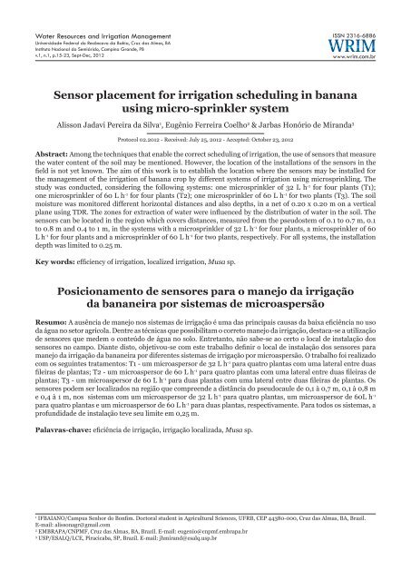
<strong>Sensor</strong> <strong>placement</strong> <strong>for</strong> <strong>irrigation</strong> <strong>schedul<strong>in</strong>g</strong> <strong>in</strong> <strong>banana</strong> us<strong>in</strong>g micro-spr<strong>in</strong>kler system 17Table 1. Physical characteristics of the soil of experimental areaDepth(m)GranulometricPorosity Soil Soil water contentcomposition (%)Textural(%) density (mclassification3 m -3 )Total sand Silt Clay Macro Micro(kg dm 3 )-10 kPa - 1500 kPaHydraulicconductivity(m s -1 x 10 -7 )0.0–0.2 57.7 09.9 32.4 Sandy clay loam 13.34 26.34 1.50 0.2106 0.1495 160.000.2 – 0.4 51.7 08.9 39.4 Sandy clay loam 11.91 28.44 1.48 0.2400 0.1709 45.280.4 – 0.6 49.3 37.4 37.4 Sandy clay loam 11.92 26.14 1.52 0.2195 0.1625 200.00coefficient (Kr) based on the surface of the soilwhich was effectively covered by <strong>banana</strong> leafarea. The frequency of <strong>irrigation</strong> was daily. Thesoil moisture was monitored at several differenthorizontal distances (R) and also depths (Z), <strong>in</strong> anet of 0.20 x 0.20 m on a vertical plane, start<strong>in</strong>gfrom the plant and follow<strong>in</strong>g the direction of theplant row, with “R” limit set at 1.0 m and a “Z”limit also set at 1.0 m. TDR probes were <strong>in</strong>stalledhorizontally at the different po<strong>in</strong>ts of the mesh, sothat one could obta<strong>in</strong> the soil water content <strong>in</strong> thewhole the plane (Figure 1).Ew<strong>in</strong>g, 1997) and of root length density (RLD)was obta<strong>in</strong>ed us<strong>in</strong>g the follow<strong>in</strong>g equation:RLD =L Vrwhere:RLD - density of root lengths, m m -3L r- length of roots, mV r- volume of samples, m 3Soil water content measurements were startedthirty days after <strong>in</strong>stallation. Read<strong>in</strong>gs were made<strong>in</strong> each plane <strong>for</strong> a period of five days by us<strong>in</strong>g aTDR attached to a datalogger, programmed tostore soil water content every 10 m<strong>in</strong>. At eachpo<strong>in</strong>t of the grid (R, Z) the extracted water depth[LE(R, Z)] was calculated based on the differencesof soil water content measured straight after<strong>irrigation</strong> (time correspond<strong>in</strong>g to that when the<strong>in</strong>filtrated water would have reached the deepestprobe <strong>in</strong> the plane (k + 1), and a time be<strong>for</strong>e thenext <strong>irrigation</strong> (k + 2), as shown <strong>in</strong> Figure 2.r(2)Figure 1. Monitor<strong>in</strong>g of soil water content <strong>in</strong> the regionaround the root system of <strong>banana</strong> plants, us<strong>in</strong>g time doma<strong>in</strong>reflectometry (TDR) probesTDR probes were made with rods of 0.1 mspaced with distances of 0.017 m between them,as used by Silva et al. (2009), with the calibrationequation given by Eq. (1):3 2θ= 6. 438ε − 5. 5246ε + 2. 0373ε−0.0745 (1)where:e - bulk dielectric constant of the soilAs the TDR probes were <strong>in</strong>stalled, samples of0.0005 m 3 of soil and roots were removed fromthe profile <strong>in</strong> order to establish root distributionof the <strong>banana</strong> crop. Roots were separated fromthe soil us<strong>in</strong>g a wash<strong>in</strong>g process (Bohm, 1979),and then digitalized us<strong>in</strong>g a scanner (Coelho &Or, 1998). Root length “Lr” (cm) was obta<strong>in</strong>edwith the use of the Rootedge software (Kaspar &Figure 2. Identification of Time Po<strong>in</strong>ts (k + 1) and(k + 2)Extracted water by the plant was estimatedat different locations on the grid [LE(Ri, Zi)] byus<strong>in</strong>g Eq. (3).LE ( RZ)= θk−θk,( + 1) ( + 2)(3)where:q (k + 1)- soil water content immediately after<strong>irrigation</strong>, m 3 m -3Water Resources and Irrigation Management, v.1, n.1, p.15-23, 2012.
18Silva et al.q (k + 2)- soil water content immediately be<strong>for</strong>ethe follow<strong>in</strong>g <strong>irrigation</strong>, m 3 m -3The concentration limits <strong>for</strong> the roots of<strong>banana</strong> plant have been established based on theknowledge of the effective root depth (ERD) andalso the effective root distance (ERDi), with “EDR”be<strong>in</strong>g def<strong>in</strong>ed as the depth that conta<strong>in</strong>s 80%of total root length and “ERDi” as the distancethat conta<strong>in</strong>s 80% of the total root length. Acharacterization of the effective extraction depth(EED) and the effective extraction distance (EEDi)was made based on the knowledge of the zonewhere most of root activity occurs. The effectiveextraction depth (EED) corresponded to the regionof the soil profile, start<strong>in</strong>g from the soil surface,where at least 80% of the total water is extractedby roots and EEDi corresponded to the region ofthe soil profile from the plant, where at least 80%of the water is also extracted by the roots. Thepercentages of soil available water were establishedat each location of the profile (R, Z), based on thesoil water characteristic curve by Eq. (4):⎛ θ( RZ , )− θAD( RZ , )=⎜⎝ θcc− θpmppmp⎞⎟ × 100⎠where:AD(R, Z) - percentage of available water at apo<strong>in</strong>t (R, Z) <strong>in</strong> the soil profileq(R, Z) - soil water content at a po<strong>in</strong>t (R, Z) ofthe soil profile, m 3 m -3q pmp- soil water content referr<strong>in</strong>g to permanentwilt<strong>in</strong>g po<strong>in</strong>t, m 3 m -3q cc- soil water content referr<strong>in</strong>g to fieldcapacity, m 3 m -3Percolation loss, DP (R, Z R) can be calculatedby Eq. (5) <strong>for</strong> each distance R just below theeffective depth of the roots, Z Rthat was assumedas 0.9 m:DP( RZ , )=Rk+2∫k+1qdtwhere:k + 1 - time when soil water content reachedits maximum value at shallow locations (R, Z) andthe wett<strong>in</strong>g front reached the depth of 0.9 mk + 2 - time of the next <strong>irrigation</strong>θt− θtq = + 1∆t(4)(5)(6)where:Dt - time <strong>in</strong>terval, 1 hq - flow of water, cm 3 h -1 , <strong>in</strong> 1 cm 3 of the soilq t- soil water content at the time tq t+1- soil water content at the time t + 1The average percolation loss <strong>in</strong> the profile, i.e,from plant to a distance R can be calculated by theEq. (7):DPm∑ DP RZ ,R=n( )where:n - number of distances (R) from the plantThe values of DPm calculated <strong>for</strong> differentmoments <strong>in</strong> time after the beg<strong>in</strong>n<strong>in</strong>g of <strong>irrigation</strong><strong>for</strong> treatments T1, T2 and T3 were compared bythe least significant difference (LSD) test at aprobability level of 0.05.Results and DiscussionWater distribution and deep percolationResults showed that the largest precipitationvalues were always registered on the collectorsfurthest away from the plants and close to themicrospr<strong>in</strong>klers, and there were records ofprecipitations of 5.1, 10.2 and 5.0 mm at a distanceof 1 m, while at a distance of 0.2 m the precipitationsas observed were 1.05, 0.35 and 2.02 mm <strong>for</strong> thetreatments T1, T2 and T3, respectively (Figure 3).There was the loss of water by percolation <strong>in</strong> allstudied treatments. Table 2 presents average valuesof percolated water depths at different momentsafter the beg<strong>in</strong>n<strong>in</strong>g of <strong>irrigation</strong> <strong>for</strong> treatments T1, T2and T3. By comparison of the means <strong>for</strong> treatmentsat specific times, the values of the percolatedwater depths varied significantly based on theconfigurations of the <strong>irrigation</strong> systems, tested up to1 hour after the start of <strong>irrigation</strong> and, after 2 and 4hours the means were different and only higher <strong>in</strong>the case of treatment T2. There were no significantdifferences <strong>in</strong> the mean percolated water depthvalues between 6 and 14 h after the start of <strong>irrigation</strong>.Root distributionThe isol<strong>in</strong>es of distribution of root lengthdensity <strong>in</strong> the soil profile and also the percentageof cumulative root length <strong>in</strong> the soil profile athorizontal distances towards the microspr<strong>in</strong>klerand depths are shown <strong>in</strong> Figures 4 and 5. Theeffective root depths <strong>in</strong> case of a microspr<strong>in</strong>klerof 32 L h -1 <strong>for</strong> four plants (T1), a microspr<strong>in</strong>kler of60 L h -1 <strong>for</strong> four plants (T2) and a microspr<strong>in</strong>klerR(7)Water Resources and Irrigation Management, v.1, n.1, p.15-23, 2012.
<strong>Sensor</strong> <strong>placement</strong> <strong>for</strong> <strong>irrigation</strong> <strong>schedul<strong>in</strong>g</strong> <strong>in</strong> <strong>banana</strong> us<strong>in</strong>g micro-spr<strong>in</strong>kler system 19A. T1 - 32 L h -1 <strong>for</strong> four plantsA. T1 - 32 L h -1 <strong>for</strong> four plants00.20.40.60.8B. T2 - 60 L h -1 <strong>for</strong> four plants1.0B. T2 - 60 L h -1 <strong>for</strong> four plantsPrecipitation (mm)Depth (m)00.20.40.61.0C. T3 - 60 L h -1 <strong>for</strong> two plants C. T3 - 60 L h -1 <strong>for</strong> two plants0.800.20.40.60.8Distance from plant (m)Figure 3. Precipitation <strong>in</strong> relation to the distance of theplant from the microspr<strong>in</strong>kler regard<strong>in</strong>g treatments T1(A), T2 (B), T3 (C)of 60 L h -1 <strong>for</strong> two plants (T3) were 0.5, 0.5 and0.6 m, respectively. Similar values were obta<strong>in</strong>edby Ramos (2001) and Garcia (2000). The effectivedistances of the roots extended to 0.8, 0.85 and0.7 m <strong>for</strong> treatments T1, T2 and T3, respectively.1.00 0.2 0.4 0.6 0.8 1.0Distance from plant (m)Figure 4. Isol<strong>in</strong>es of root density length (<strong>in</strong> m -3 ) of<strong>banana</strong> plants us<strong>in</strong>g the treatments T1 (A), T2 (B) andT3 (C)Soil water extractionFigure 6 shows the percentage distributionof the water availability <strong>in</strong> the soil immediatelyafter the end of the <strong>irrigation</strong>. Superimpos<strong>in</strong>gthe isol<strong>in</strong>es of available water, the isol<strong>in</strong>es <strong>for</strong>Table 2. Mean percolation values at different times (hours - h) after <strong>irrigation</strong>Percolated water (mm)Treat.1h 2h 4h 6h 8h 10h 12h 14hT1 0.1878ab 0.1165a 0.1147a 0.1015a 0.0871a 0.0344a 0.0117a 0.0056aT2 0.2531ba 0.4960b 0.2416b 0.1024a 0.0752a 0.0970a 0.0136a 0.0009aT3 0.1097ab 0.1175a 0.0968a 0.1156a 0.0953a 0.0419a 0.0253a 0.0118a* Means followed by the same letter do not show statistically significant differences accord<strong>in</strong>g to the t-test (LSD) at a probability level of 0.05#T1, T2 and T3 correspond respectively to a microspr<strong>in</strong>kler of 32 L h -1 <strong>for</strong> four plants, 60 L h -1 <strong>for</strong> four plants and 60 L h -1 <strong>for</strong> two plantsWater Resources and Irrigation Management, v.1, n.1, p.15-23, 2012.
20Silva et al.A.A. T1 - 32 L h -1 <strong>for</strong> four plants00.20.40.60.8B.1.0B. T2 - 60 L h -1 <strong>for</strong> four plantsTotal length of roots (%)Depth (m)00.20.40.60.8C.1.0C. T3 - 60 L h -1 <strong>for</strong> two plants00.20.40.60.8Distance from plant (m)Figure 5. Percentages of accumulated root lengths <strong>in</strong>the soil profile at horizontal distances towards the microspr<strong>in</strong>kler(R) and depths (Z)the water extraction from the soil betweentimes k+1 and k+2 was observed (blue dashedl<strong>in</strong>es). The distribution of available water takesplace <strong>in</strong> a nonuni<strong>for</strong>m way, i.e., the soil watercontents get higher from the plant towards to themicrospr<strong>in</strong>kler, co<strong>in</strong>cid<strong>in</strong>g to the regions wherethe largest volumes of water were collected on thesoil surface, as applied by the microspr<strong>in</strong>klers.It is also observed thet the zones <strong>for</strong> extractionof water were <strong>in</strong>fluenced by the distribution ofwater <strong>in</strong> the soil. The mean percentage of availablewater of 64.44% <strong>for</strong> treatment T1 was obta<strong>in</strong>ed at1.00 0.2 0.4 0.6 0.8 1.0Distance from plant (m)Figure 6. Distribution of percentage of available wateron the ground and also <strong>in</strong> the water extraction zones <strong>in</strong>the soil, <strong>for</strong> T1 (A), T2 (B), T3 (C)a distance of 0.2 m and the percentage of waterextracted was 11.38% of the total extracted fromthe effective root distribution zone. The availablewater was 94.09% at the distance of 0.8 m wherethe extraction was 30.95% of the total. Thepercentage of water available <strong>in</strong> treatment T2 was49.3% soon after the end of <strong>irrigation</strong> at a distanceof 0.2 m, with a total occurrence of 10.83% ofthe total water extracted by the plant. The meansoil water available was 84.26%, <strong>for</strong> this sametreatment but at a distance of 0.8 m with theoccurrence of 31.76% of the total water extraction.Water Resources and Irrigation Management, v.1, n.1, p.15-23, 2012.
<strong>Sensor</strong> <strong>placement</strong> <strong>for</strong> <strong>irrigation</strong> <strong>schedul<strong>in</strong>g</strong> <strong>in</strong> <strong>banana</strong> us<strong>in</strong>g micro-spr<strong>in</strong>kler system 21In treatment T3, the mean soil water availableat 0.2 m was 57%, where there was also 8.17%of the total water extraction. The water contentwas 60.67%, with 24.42% of the total extractionof water at the distance of 0.8 m. These resultsemphasize the ones found by other authors (Zhanget al., 1996; Elmaloglou & Diamantopoulos, 2009;Hutton & Loveys, 2011) <strong>in</strong> which, the <strong>irrigation</strong>system affected the zones of water extraction by theplant. Star<strong>in</strong>g from the pseudostem of the plants,effective water extraction distance of up to 0.7,0.8 and 0.9 m was obta<strong>in</strong>ed <strong>for</strong> a microspr<strong>in</strong>klerof 32 L h -1 <strong>for</strong> four plants, a microspr<strong>in</strong>kler of 60L h -1 <strong>for</strong> four plants and also a microspr<strong>in</strong>klerof 60 L h -1 <strong>for</strong> two plants, respectively. Effectivewater extraction depth observed was 0.25 m <strong>for</strong>all systems (Figure 7).A. T1 - 32 L h -1 <strong>for</strong> four plants<strong>Sensor</strong> <strong>placement</strong>Water sensors can be <strong>in</strong>stalled <strong>in</strong> the soil regionwhich covers distances between 0.1 and 0.7 m,and can be <strong>in</strong>stalled to a depth of 0.25 m <strong>in</strong> systemT1 (Figure 8A). In case of system T2, sensors canbe <strong>in</strong>stalled up to a distance of 0.8 m from thepseudostem of the plant, with the maximum depthbe<strong>in</strong>g 0.25 m (Figure 8B). In the case of systemT3, sensors may be located at a distance of 0.4m up to a distance of 0.9 m, with the maximumdepth be<strong>in</strong>g 0.25 m (Figure 8C).With the use of tensiometers, due to the fact thatthis technique is limited to a tension of 80 kPa, the<strong>in</strong>stallation region was reduced to the locations,where potentials observed were above -80 kPabe<strong>for</strong>e the start of <strong>irrigation</strong>. The suitable location<strong>for</strong> <strong>in</strong>stallation of tensiometers <strong>for</strong> treatment T1A. T1 - 32 L h -1 <strong>for</strong> four plants00.20.40.60.8B. T2 - 60 L h -1 <strong>for</strong> four plants1.0B. T2 - 60 L h -1 <strong>for</strong> four plantsTotal water extraction (%)Depth (m)00.20.40.60.8C. T3 - 60 L h -1 <strong>for</strong> two plants1.0C. T3 - 60 L h -1 <strong>for</strong> two plants00.20.40.60.8Distance from plant (m)Figure 7. Percentages of accumulated water extraction,by distance and depth, <strong>for</strong> T1 (A), T2 (B), T3 (C)1.00 0.2 0.4 0.6 0.8 1.0Distance from plant (m)Figure 8. Suitable region <strong>for</strong> the location of water sensors<strong>in</strong> the soil (limited <strong>in</strong> blue) <strong>for</strong> the treatments: T1(A), T2 (B) and T3 (C)Water Resources and Irrigation Management, v.1, n.1, p.15-23, 2012.
22Silva et al.A. T1 - 32 L h -1 <strong>for</strong> four plants00.20.432 L h -1 <strong>for</strong> four plants, a microspr<strong>in</strong>kler of 60 L h -1<strong>for</strong> four plants and a microspr<strong>in</strong>kler of 60 L h -1 <strong>for</strong>two plants, respectively.2. For all systems, the <strong>in</strong>stallation depth shouldbe limited to 0.25 m.Literature CitedDepth (m)0.60.81.0B. T2 - 60 L h -1 <strong>for</strong> four plants00.20.40.60.81.0C. T3 - 60 L h -1 <strong>for</strong> two plants00.20.40.60.81.00 0.2 0.4 0.6 0.8 1.0Distance from plant (m)Figure 9. Suitable region <strong>for</strong> the tensiometers <strong>placement</strong><strong>in</strong> the soil (delimited by the blue l<strong>in</strong>e) <strong>for</strong> treatments T1(A), T2 (B) and T3 (C)is the region between 0.5 and 0.7 m from theplant, limited to a depth of 0.25 m (Figure 9A).In treatment T2, the region <strong>for</strong> the <strong>in</strong>stallation oftensiometers is that compris<strong>in</strong>g between 0.5 and0.8 m, with a maximum depth of 0.25 m (Figure9B). In treatment T3, it is recommended that thetensiometers be <strong>in</strong>stalled at a distance between0.5 m and 1 m, at a depth of 0.2 m (Figure 9C).Conclusions1. The sensors to monitor water content <strong>for</strong><strong>irrigation</strong> <strong>schedul<strong>in</strong>g</strong> can be located <strong>in</strong> the regionwhich covers distances, measured from thepseudostem, of 0.1 to 0.7 m, 0.1 to 0.8 m and 0.4to 0.9 m, <strong>in</strong> the systems with a microspr<strong>in</strong>kler ofAhmadi, S. H.; Plauborg, F.; Andersen, M. N.;Sepaskhah, A. R.; Jensen, C. R.; Hansen, S. Effectsof <strong>irrigation</strong> strategies and soils on field grownpotatoes: Root distribution. Agricultural WaterManagement, v.98, p.1280-1290, 2011.Bohm, W. Methods of study<strong>in</strong>g root systems. NewYork: Spr<strong>in</strong>ger Verlag, 1979. 190p.Clothier, B. E.; Green, S. R. Rootzone processes and theefficient use of <strong>irrigation</strong> water. Agricultural WaterManagement, v.25, p.1-12, 1994.Coelho, E. F.; Or, D. Root distribution and water uptakepatterns of corn under surface and subsurface drip<strong>irrigation</strong>. Plant and Soil, v.206, p.123-136, 1998.Coelho, E. F.; Santos, D. B.; Azevedo, C. A. V. de. <strong>Sensor</strong><strong>placement</strong> <strong>for</strong> soil water monitor<strong>in</strong>g <strong>in</strong> lemonirrigated by micro spr<strong>in</strong>kler. Revista Brasileira deEngenharia Agrícola e Ambiental, v.11, p.46-52,2007.Coelho Filho, M. A. Variabilidade espacial aplicadaao manejo da irrigação por microaspersão emlima ácida ‘Tahiti” (Citrus latifólia TANAKA).Piracicaba: Escola Superior de Agricultura “Luiz deQueiroz”, 1998. 152p. Dissertação MestradoCruz, A. C. R.; Libardi, P. L.; Carvalho, L. A.; Rocha,G. C. Balanço de água no volume de solo exploradopelo sistema radicular de uma planta de citros.Revista Brasileira de Ciência do Solo, v.29, p.1-10,2005.Doorenbos, J.; Kassam, A. H. Efeito da água norendimento das culturas. Camp<strong>in</strong>a Grande: UFPB.2000. 306p.Elmaloglou. E.; Diamántopoulos, E. Simulation of soilwater dynamics under subsurface drip <strong>irrigation</strong>from l<strong>in</strong>e sources. Agricultural Water Management,v.96, p.1587-1595, 2009.Garcia, R. V. Sistema radicular de bananeira irrigadapor aspersão convencional e microaspersão noProjeto Jaíba - MG. Viçosa: Universidade Federalde Viçosa, 2000. 47p. Dissertação MestradoGuohua, L.; Yaohu, K.; Lan, L.; Shuq<strong>in</strong>, W. Effectof <strong>irrigation</strong> methods on root development andprofile soil water uptake <strong>in</strong> w<strong>in</strong>ter wheat. IrrigationScience, v.28, p.387-398, 2010.Heimovaara, T. J.; Huisman, J. A.; Vrugt, J. A.; Bouten,W. Obta<strong>in</strong><strong>in</strong>g the spatial distribution of watercontent along a TDR probe us<strong>in</strong>g the SCEM-UAbayesian <strong>in</strong>verse model<strong>in</strong>g scheme. Vadose ZoneJournal, v.3, p.128-145, 2004.Hendrickx, J. M. H.; Wierenga, P. L. Variability of soilwater tension <strong>in</strong> a trickle irrigated field. IrrigationScience, v.11, p.23-30, 1990.Water Resources and Irrigation Management, v.1, n.1, p.15-23, 2012.
<strong>Sensor</strong> <strong>placement</strong> <strong>for</strong> <strong>irrigation</strong> <strong>schedul<strong>in</strong>g</strong> <strong>in</strong> <strong>banana</strong> us<strong>in</strong>g micro-spr<strong>in</strong>kler system 23Hutton, R. J.; Loveys, B. R. A partial root zonedry<strong>in</strong>g <strong>irrigation</strong> strategy <strong>for</strong> citrus. Effects onwater use efficiency and fruit characteristics.Agricultural Water Management, v.98, p.1485-1496, 2011.IWMI - International Water Management Institute.World water and climate atlas. 2000. . 07 Feb. 2009.Kaspar, T. C.; Ew<strong>in</strong>g, R. P. Rootedge: Software <strong>for</strong>measur<strong>in</strong>g root length from desktop scanner images.Agronomy Journal, v.89, p.932-940. 1997.Mantovani, E. C.; Bernardo, S.; Palaretti, L. F.Irrigação: Pr<strong>in</strong>cípios e métodos. Viçosa: UFV,2006. v.1, 318p.Ramos, C. M. C. Distribuição do sistema radiculare consumo de água da bananeira irrigada pormicroaspersão. Viçosa: UFV, 2001. 62p. DissertaçãoMestradoSilva, A. J. P. da; Coelho, E. F.; Miranda, J. H. de; Workman,S.R. Estimat<strong>in</strong>g water application efficiency <strong>for</strong> drip<strong>irrigation</strong> emitter patterns on <strong>banana</strong>. PesquisaAgropecuária Brasileira, v.44, p.730-737, 2009Salgado, E.; Caut<strong>in</strong>, R. Avocado root distribution<strong>in</strong> f<strong>in</strong>e and coarse-textured soils under drip andmicrospr<strong>in</strong>kler <strong>irrigation</strong>. Agricultural WaterManagement, v.95, p.817-824, 2008.Sokalska, D. I.; Haman, D. Z.; Szewczuk, A.; Sobota, J.;Deren, D. Spatial root distribution of mature appletrees under drip <strong>irrigation</strong> system. AgriculturalWater Management, v.96, p.917-924, 2009.Toepfer, K. Our Planet. UNEP magaz<strong>in</strong>e <strong>for</strong> environmentallysusta<strong>in</strong>able development, Issue on Freshwater.1998. . 15 Jan. 2009.Zhang, M.; Alva, A. K.; Li, Y. C.; Calvert, D. V. Rootdistribution of grapefruit trees under dry granularbroadcast vs. fert<strong>irrigation</strong> method. Plant and Soil,v.183, p.79-84, 1996.Water Resources and Irrigation Management, v.1, n.1, p.15-23, 2012.